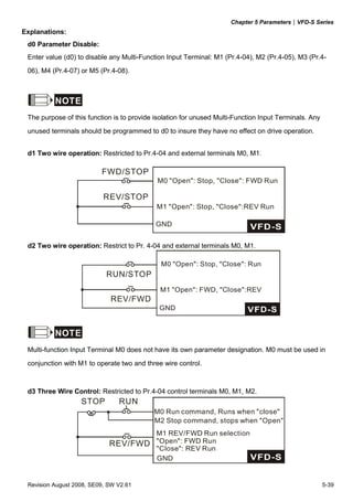
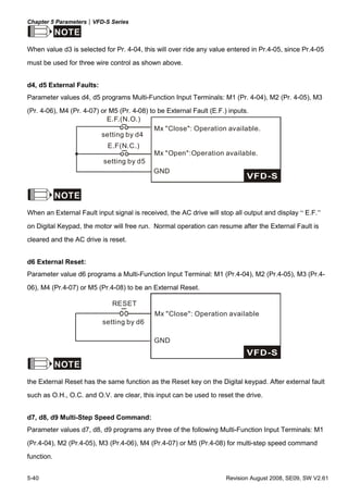
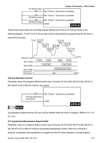
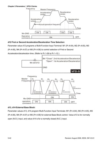
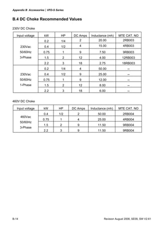
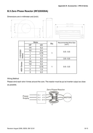
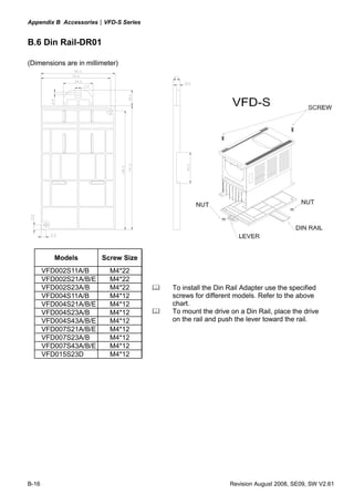
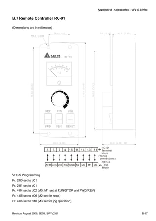
Downloaded 50 times


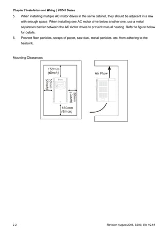
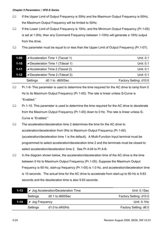
![Chapter 2 Installation and Wiring|VFD-S Series
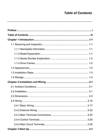
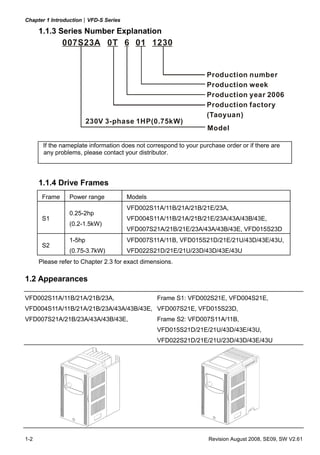
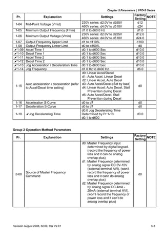
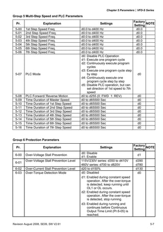
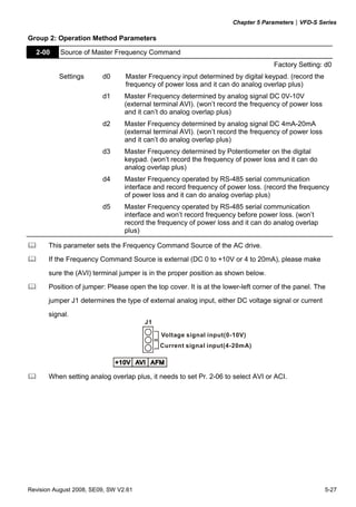
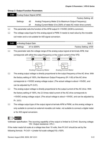
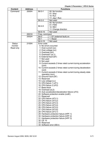
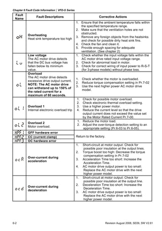
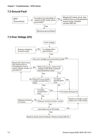
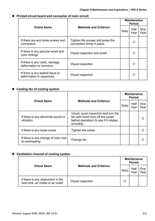
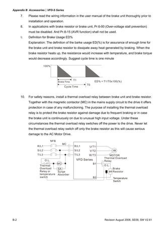
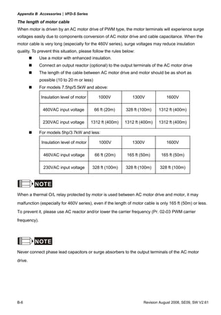
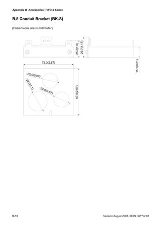
2.3 Dimensions
(Dimensions are in millimeter and [inch])
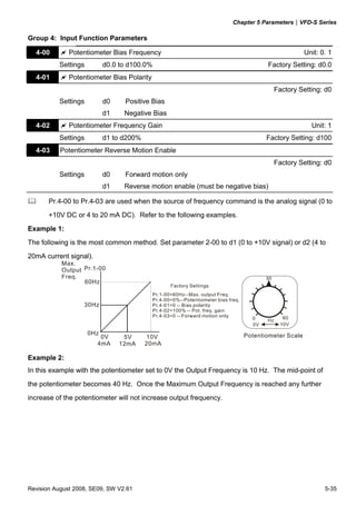
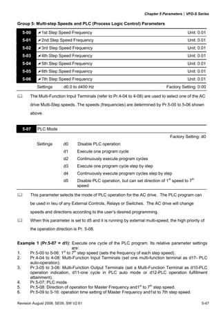
Frame S1: VFD002S11A, VFD002S21A, VFD002S23A
85.0 [3.35] 5.8 [0.23] 88.0 [3.47]
74.0 [2.92] 13.0 [0.51]
132.2 [5.21]
148.0 [5.83]
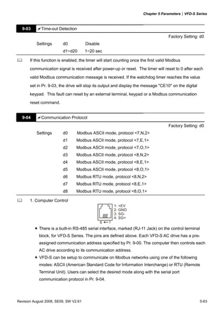
3.0 [0.12]
5.0 [0.20]
8.1 [0.32]
11.1 [0.44]
5.0 [0.20]
Revision August 2008, SE09, SW V2.61 2-3](https://image.slidesharecdn.com/vfd-smanualen-120815032409-phpapp01/85/Vfd-s-manual-en-18-320.jpg)
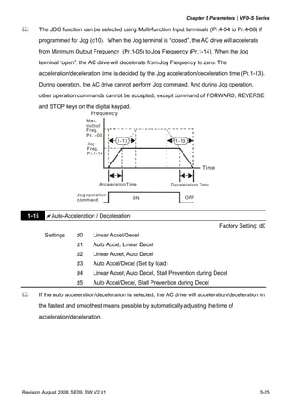
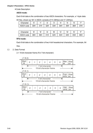
![Chapter 2 Installation and Wiring|VFD-S Series
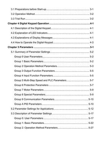
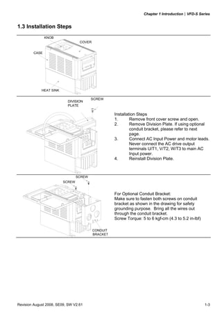
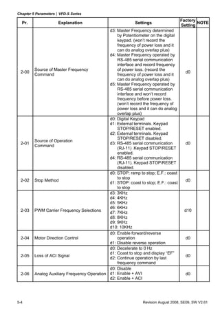
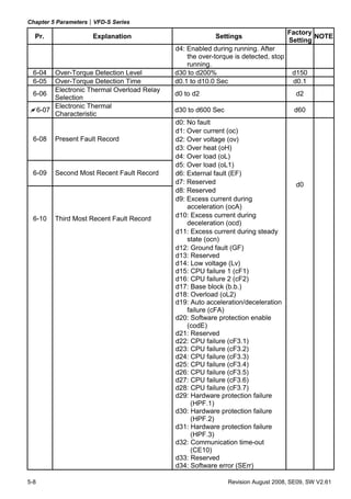
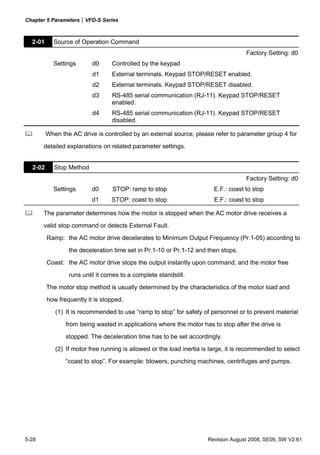
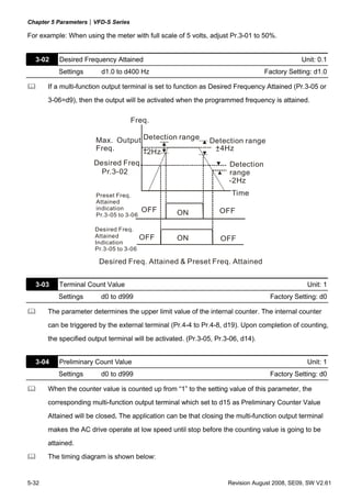
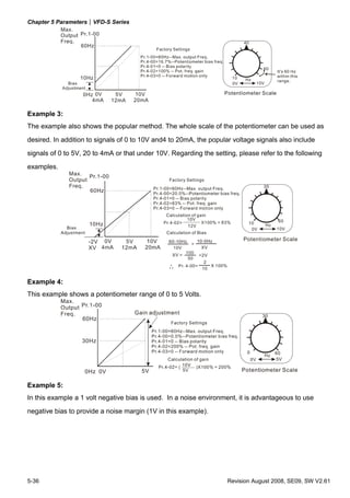
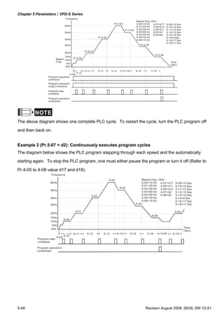
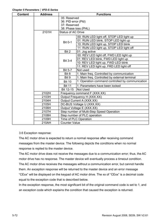
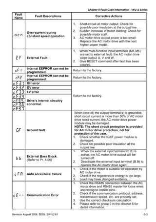
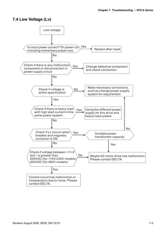
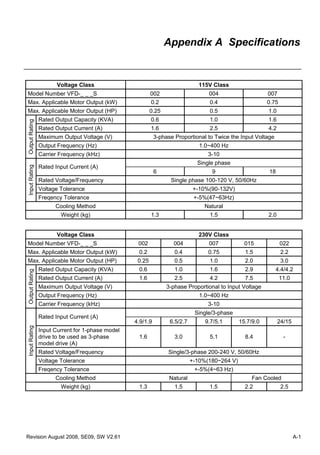
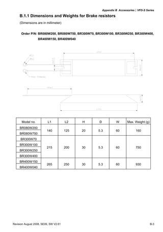
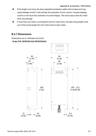
Frame S1: VFD002S11B, VFD002S21B
8 5 .0 [3 .3 5] 5 . 8 [0. 23 ] 88 .0 [3 .4 7 ]
74 .0 [2 .9 2] 1 3 .0 [0 .5 1]
14 8.0 [ 5.83]
13 2.2 [5.21]
73 .0 [2 .8 8 ] 67 .8 [2 .6 7] 13 .0 [0 .5 1]
1 6.0 [ 0.63]
3.0 [0.12]
5 . 0 [0. 20 ]
8.1 [0.32]
5. 0 [0 . 20 ]
1 1.1 [ 0.44]
2-4 Revision August 2008, SE09, SW V2.61](https://image.slidesharecdn.com/vfd-smanualen-120815032409-phpapp01/85/Vfd-s-manual-en-19-320.jpg)
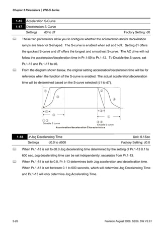
![Chapter 2 Installation and Wiring|VFD-S Series
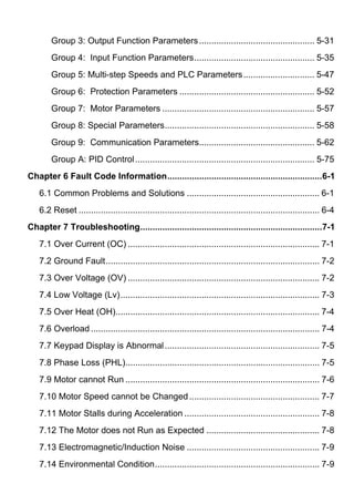
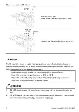
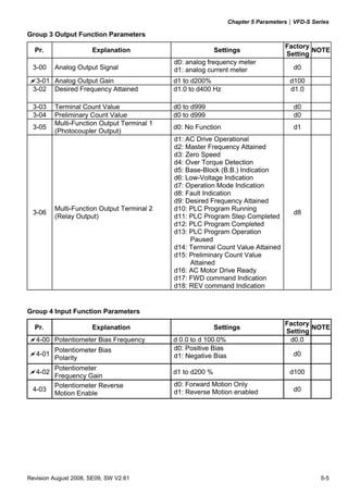
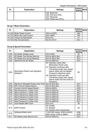
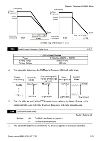
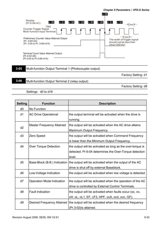
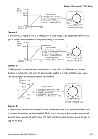
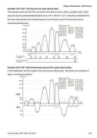
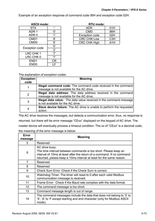
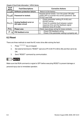
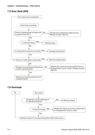
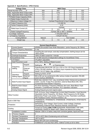
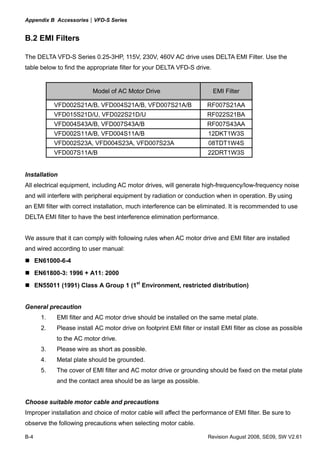
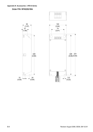
Frame S1: VFD004S11A, VFD004S21A, VFD004S23A
8 5 .0 [3 .3 5] 5. 8 [0 . 23 ] 10 2 . 0 [ 4. 02 ]
7 4 .0 [2 .9 2] 2 . 8 [0. 11 ]
1 48.0 [5.83]
1 32.2 [5.21]
3.0 [ 0.12]
5 . 0 [0. 2 0 ]
8 .1 [0.32]
1 1.1 [0.44]
5. 0 [0. 20 ]
Revision August 2008, SE09, SW V2.61 2-5](https://image.slidesharecdn.com/vfd-smanualen-120815032409-phpapp01/85/Vfd-s-manual-en-20-320.jpg)
![Chapter 2 Installation and Wiring|VFD-S Series
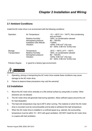
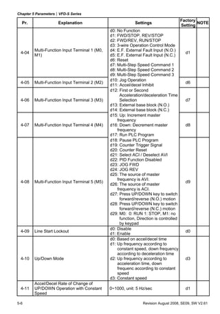
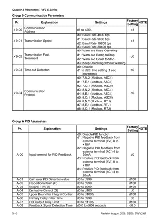
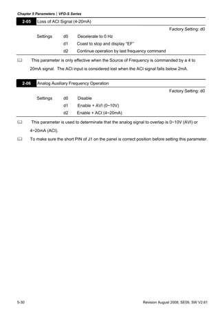
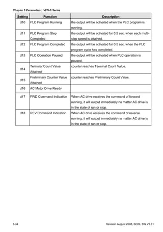
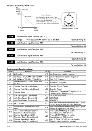
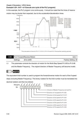
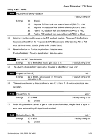
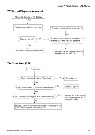
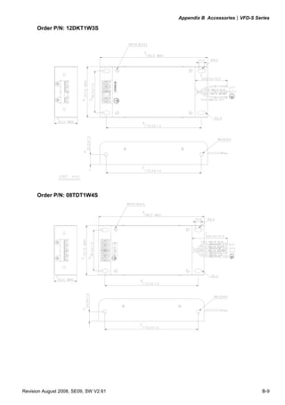
Frame S1: VFD004S11B, VFD004S21B
85 .0 [3 .3 5] 5. 8 [0. 23 ] 10 2. 0 [ 4. 02 ]
74 .0 [2 .9 2] 2 . 8 [0. 11 ]
1 32 .2 [5.21]
1 48 .0 [5.83]
73 .0 [2 .8 8 ] 67 .8 [2 .6 7] 27 .0 [1 .0 6]
1 6.0 [0 .63]
3 .0 [0 .12]
5. 0 [0 . 2 0 ] 8.1 [ 0.32]
5. 0 [0 . 2 0 ]
11 .1 [0 .44]
2-6 Revision August 2008, SE09, SW V2.61](https://image.slidesharecdn.com/vfd-smanualen-120815032409-phpapp01/85/Vfd-s-manual-en-21-320.jpg)
![Chapter 2 Installation and Wiring|VFD-S Series
Frame S1: VFD007S21A, VFD007S23A
85 .0 [3 .3 5] 5. 8 [0. 23 ] 12 4. 0 [ 4. 89]
74 .0 [2 .9 2] 2. 8 [0. 11 ]
13 2.2 [ 5.21]
14 8.0 [ 5.83]
3.0 [0 .12]
5. 0 [0. 20 ]
8.1 [ 0.32]
1 1.1 [ 0.44]
5. 0 [0. 20 ]
Revision August 2008, SE09, SW V2.61 2-7](https://image.slidesharecdn.com/vfd-smanualen-120815032409-phpapp01/85/Vfd-s-manual-en-22-320.jpg)
![Chapter 2 Installation and Wiring|VFD-S Series
Frame S1: VFD007S21B
85 .0 [3 .3 5] 5. 8 [0. 23 ] 12 4. 0 [ 4. 89]
74 .0 [2 .9 2] 2. 8 [0. 11 ]
148.0 [5.83]
1 32.2 [5.21]
73 .0 [2 .8 8] 67 .8 [2 .6 7] 50 .0 [1 .9 7]
16.0 [0.63]
3. 0 [0.12]
5. 0 [0. 20 ]
8.1 [0.32]
11 .1 [0.44]
5. 0 [0. 20 ]
2-8 Revision August 2008, SE09, SW V2.61](https://image.slidesharecdn.com/vfd-smanualen-120815032409-phpapp01/85/Vfd-s-manual-en-23-320.jpg)
![Chapter 2 Installation and Wiring|VFD-S Series
Frame S1: VFD004S43A, VFD004S43E, VFD007S43A, VFD007S43E
85 .0 [3 .3 5] 5. 8 [0. 23 ] 12 6. 0 [ 4. 96]
74 .0 [2 .9 2] 3. 0 [0. 12 ]
13 2.2 [ 5.21]
14 8.0 [ 5.83]
3.0 [0 .12]
5. 0 [0. 20 ]
8.1 [0.32]
1 1.1 [ 0.44]
5. 0 [0. 20 ]
Revision August 2008, SE09, SW V2.61 2-9](https://image.slidesharecdn.com/vfd-smanualen-120815032409-phpapp01/85/Vfd-s-manual-en-24-320.jpg)
![Chapter 2 Installation and Wiring|VFD-S Series
Frame S1: VFD004S43B, VFD007S43B
85 .0 [3 .3 5] 5. 8 [0. 23 ] 12 6. 0 [ 4. 96]
74 .0 [2 .9 2] 3 . 0 [0. 12 ]
1 4 8.0 [5.83]
1 32 .2 [5.21 ]
73 .0 [2 .8 8] 67 .8 [2 .6 7] 51 .0 [2 .0 1]
16 .0 [0.63]
3 . 0 [0 .1 2]
5. 0 [0 . 20 ]
8 .1 [0 .32]
11 .1 [0 .44]
5 . 0 [0. 20 ]
2-10 Revision August 2008, SE09, SW V2.61](https://image.slidesharecdn.com/vfd-smanualen-120815032409-phpapp01/85/Vfd-s-manual-en-25-320.jpg)
![Chapter 2 Installation and Wiring|VFD-S Series
Frame S1: VFD002S21E, VFD004S21E, VFD007S21E, VFD015S23D
85 .0 [3 .3 5] 5. 8 [ 0. 23 ] 12 7. 0 [ 5. 00]
74 .0 [2 .9 2] 8. 5 [ 0. 33 ]
13 3.7 [ 5.27]
14 8.0 [ 5.83]
8.3 [ 0.33]
5. 0 [ 0. 20 ]
Revision August 2008, SE09, SW V2.61 2-11](https://image.slidesharecdn.com/vfd-smanualen-120815032409-phpapp01/85/Vfd-s-manual-en-26-320.jpg)
![Chapter 2 Installation and Wiring|VFD-S Series
Frame S2: VFD007S11A
10 0. 0 [ 3. 94]
86 .5 [3 .4 1] 5. 4 [0. 21 ] 12 9. 0 [ 5. 08]
1 8 6.0 [7.33]
1 73.0 [6.81]
5. 5 [0. 22 ]
6.5 [ 0.26]
1 .0 [0 .04]
5. 5 [0. 22 ]
9 .5 [0 .38]
2-12 Revision August 2008, SE09, SW V2.61](https://image.slidesharecdn.com/vfd-smanualen-120815032409-phpapp01/85/Vfd-s-manual-en-27-320.jpg)
![Chapter 2 Installation and Wiring|VFD-S Series
Frame S2: VFD007S11B
10 0. 0 [ 3. 94]
86 .5 [3 .4 1] 5. 4 [0. 21 ] 12 9. 0 [ 5. 08]
18 6.0 [7.33]
173 .0 [6.82]
73 .0 [2 .8 8] 67 .8 [2 .6 7] 53 .5 [2 .11]
16 .0 [0 .63]
5. 5 [0. 22 ]
6.5 [0.26]
1.0 [0 .04]
5. 5 [0. 22 ]
9.5 [0 .38]
Revision August 2008, SE09, SW V2.61 2-13](https://image.slidesharecdn.com/vfd-smanualen-120815032409-phpapp01/85/Vfd-s-manual-en-28-320.jpg)
![Chapter 2 Installation and Wiring|VFD-S Series
Frame S2: VFD015S21D, VFD015S21E, VFD015S43D, VFD015S43E, VFD022S21D,
VFD022S21E, VFD022S23D, VFD022S43D, VFD022S43E
10 0 . 0 [ 3. 94 ] 5 . 4 [0. 2 1 ] 12 9. 3 [ 5. 09]
86 .5 [3 .4 1] 8. 5 [0. 33 ]
1 7 3 .0 [ 6.82]
1 8 6 .0 [ 7.33]
5. 5 [0. 22 ]
1.0 [0.04]
6 .5 [0.26]
9 .5 [0 .37]
5. 5 [0. 22 ]
2-14 Revision August 2008, SE09, SW V2.61](https://image.slidesharecdn.com/vfd-smanualen-120815032409-phpapp01/85/Vfd-s-manual-en-29-320.jpg)
![Chapter 2 Installation and Wiring|VFD-S Series
Frame S2: VFD015S21U, VFD015S43U, VFD022S21U, VFD022S43U
100.0 [3.94] 5.4 [0.21] 129.3 [5.09]
86.5 [3.41] 8.5 [0.33]
173.0 [6.82]
186.0 [7.33]
73.0 [2.88] 67.8 [2.67] 53.9 [2.12]
16.0 [0.63]
5.5 [0.22]
1.0 [0.04]
6.5 [0.26]
9.5 [0.37]
5.5 [0.22]
Revision August 2008, SE09, SW V2.61 2-15](https://image.slidesharecdn.com/vfd-smanualen-120815032409-phpapp01/85/Vfd-s-manual-en-30-320.jpg)

![Chapter 2 Installation and Wiring|VFD-S Series
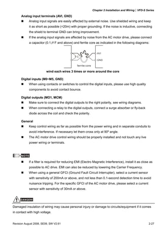
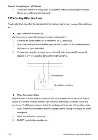
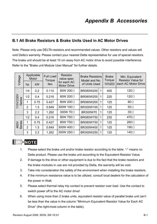
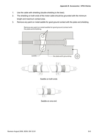
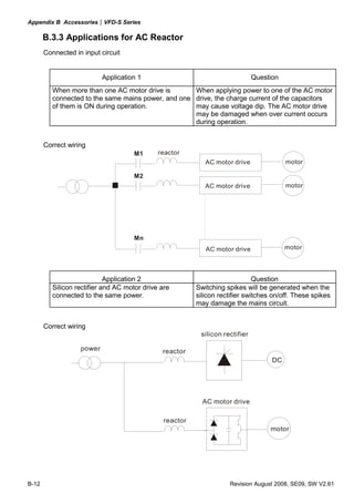
DO NOT connect phase-compensation capacitors or surge absorbers at the output
terminals of AC motor drives.
With long motor cables, high capacitive switching current peaks can cause over-current,
high leakage current or lower current readout accuracy. To prevent this, the motor cable
should be less than 20m for 3.7kW models and below. And the cable should be less than
50m for 5.5kW models and above. For longer motor cables use an AC output reactor.
Use a well-insulated motor, suitable for inverter operation.
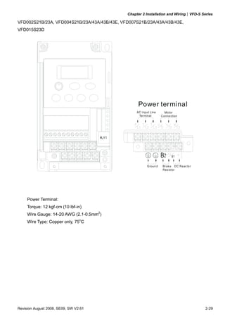
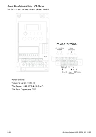
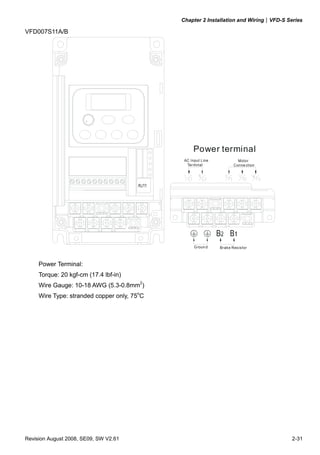
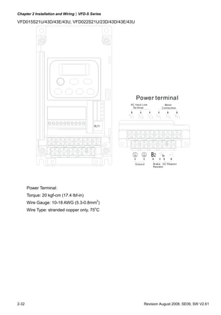
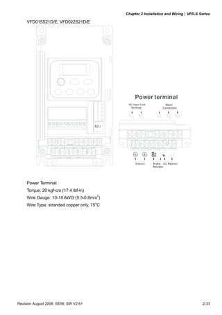
Terminals [+2/B1, +1] for connecting DC reactor
This is the connector for the DC reactor to improve the power factor. Please remove the
short jumper when connecting DC reactor.
Terminals [+2/B1, B2] for connecting brake resistor
Bra ke resistor(o ptiona l)
Ref er to A ppend ix B fo r the use of
s pecial brake resistor.
BR
+2 /B1 B2
Connect a brake resistor in applications with frequent deceleration ramps, short
deceleration time, too low brake torque or requiring increased brake torque.
WARNING!
Short-circuiting [+2/B1, B2] can damage the AC motor drive.
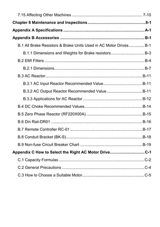
Grounding terminals ( )
Make sure that the leads are connected correctly and the AC drive is properly grounded.
(Ground resistance should not exceed 0.1Ω.)
Use ground leads that comply with local regulations and keep them as short as possible.
Multiple VFD-S units can be installed in one location. All the units should be grounded
directly to a common ground terminal, as shown in the figure below. Ensure there are
no ground loops.
excellent good not allowed
2-24 Revision August 2008, SE09, SW V2.61](https://image.slidesharecdn.com/vfd-smanualen-120815032409-phpapp01/85/Vfd-s-manual-en-39-320.jpg)


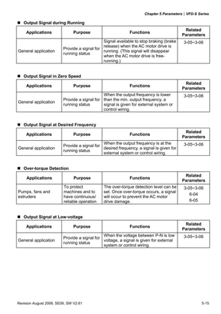
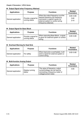
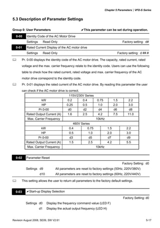
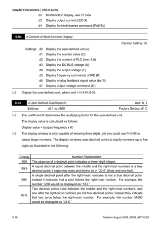
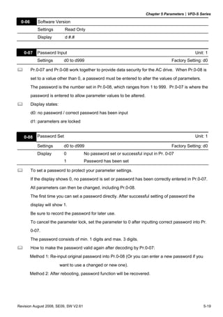
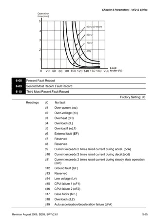
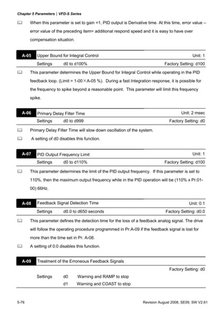
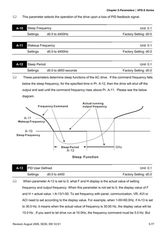
![Chapter 5 Parameters|VFD-S Series
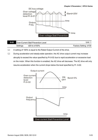
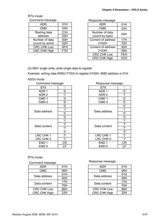
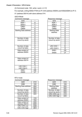
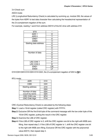
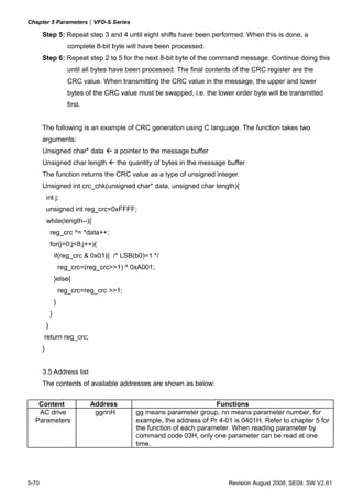
3.7 Communication program of PC:
The following is a simple example of how to write a communication program for Modbus ASCII
mode on a PC in C language.
#include<stdio.h>
#include<dos.h>
#include<conio.h>
#include<process.h>
#define PORT 0x03F8 /* the address of COM1 */
/* the address offset value relative to COM1 */
#define THR 0x0000
#define RDR 0x0000
#define BRDL 0x0000
#define IER 0x0001
#define BRDH 0x0001
#define LCR 0x0003
#define MCR 0x0004
#define LSR 0x0005
#define MSR 0x0006
unsigned char rdat[60];
/* read 2 data from address 2102H of AC drive with address 1 */
unsigned char tdat[60]={':','0','1','0','3','2','1','0',’2', '0','0','0','2','D','7','r','n'};
void main(){int i;
outportb(PORT+MCR,0x08); /* interrupt enable */
outportb(PORT+IER,0x01); /* interrupt as data in */
outportb(PORT+LCR,(inportb(PORT+LCR) | 0x80));
/* the BRDL/BRDH can be access as LCR.b7==1 */
outportb(PORT+BRDL,12); /* set baudrate=9600, 12=115200/9600*/
outportb(PORT+BRDH,0x00);
outportb(PORT+LCR,0x06); /* set protocol, <7,N,2>=06H, <7,E,1>=1AH, <7,O,1>=0AH,
<8,N,2>=07H, <8,E,1>=1BH, <8,O,1>=0BH */
for(i=0;i<=16;i++){
while(!(inportb(PORT+LSR) & 0x20)); /* wait until THR empty */
outportb(PORT+THR,tdat[i]); /* send data to THR */ }
i=0;
while(!kbhit()){
if(inportb(PORT+LSR) & 0x01){ /* b0==1, read data ready */
rdat[i++]=inportb(PORT+RDR); /* read data form RDR */
} } }
5-74 Revision August 2008, SE09, SW V2.61](https://image.slidesharecdn.com/vfd-smanualen-120815032409-phpapp01/85/Vfd-s-manual-en-131-320.jpg)


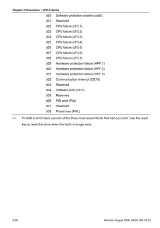
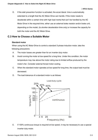
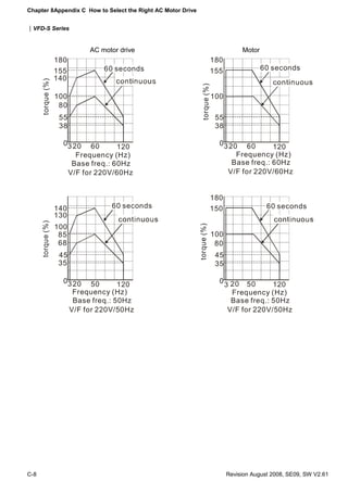
![Chapter 8Appendix C How to Select the Right AC Motor Drive
|VFD-S Series
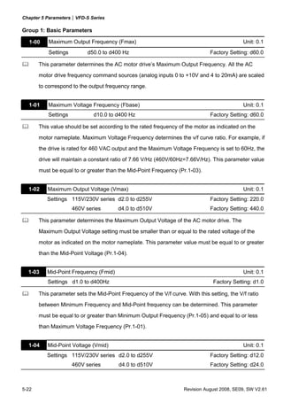
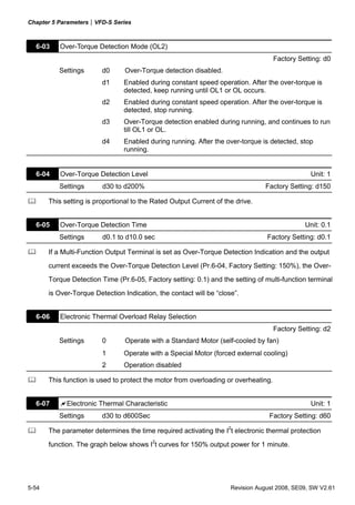
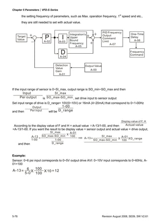
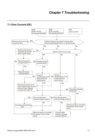
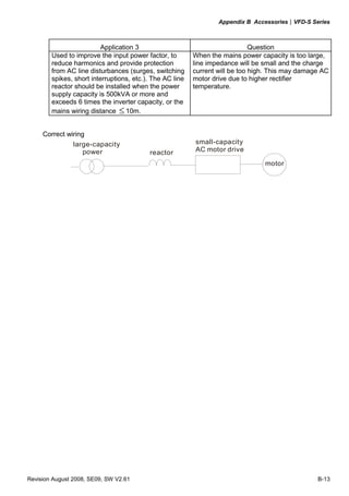
C.1 Capacity Formulas
1. When one AC motor drive operates one motor
The starting capacity should be less than 1.5x rated capacity of AC motor drive
The starting capacity is
k×N ⎛ GD 2 N ⎞
⎜ TL + × ⎟ ≤ 1.5 × the _ capacity _ of _ AC _ motor _ drive ( kVA)
973 × η × cos ϕ ⎜
⎝ 375 t A ⎟
⎠
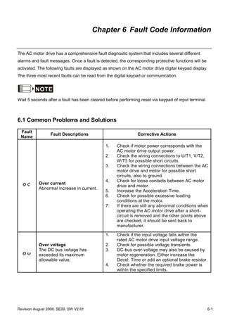
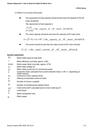
2. When one AC motor drive operates more than one motor
2.1 The starting capacity should be less than the rated capacity of the AC motor drive
Acceleration time ≦60 seconds
The starting capacity is
k×N ⎡ ns ⎤
[n T + ns (ks − 1)] = PC1⎢1 +
⎢ (ks − 1)⎥⎥ ≤ 1.5 × the _ capacity _ of _ AC _ motor _ drive(kVA)
η × cos ϕ ⎢
⎣ nT ⎥
⎦
Acceleration time ≧60 seconds
The starting capacity is
k×N ⎡ ns ⎤
[n T + ns (ks − 1)] = PC1⎢1 +
⎢ (ks − 1)⎥⎥ ≤ the _ capacity _ of _ AC _ motor _ drive(kVA)
η × cosϕ ⎢
⎣ nT ⎥
⎦
2.2 The current should be less than the rated current of the AC motor drive(A)
Acceleration time ≦60 seconds
⎢
nS ⎛
nT + IM ⎡1+ nT ⎜ kS −1⎟ ⎤ ≤ 1.5 × the _ rated _ current _ of _ AC _ motor _ drive( A)
⎞⎥
⎣ ⎝ ⎠⎦
Acceleration time ≧60 seconds
⎢
nS ⎛
nT + IM ⎡1+ nT ⎜ kS −1⎟ ⎤ ≤ the _ rated _ current _ of _ AC _ motor _ drive( A)
⎞⎥
⎣ ⎝ ⎠⎦
C-2 Revision August 2008, SE09, SW V2.61](https://image.slidesharecdn.com/vfd-smanualen-120815032409-phpapp01/85/Vfd-s-manual-en-179-320.jpg)


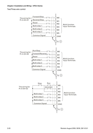
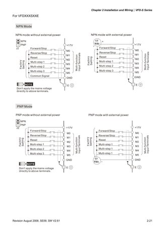
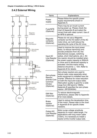
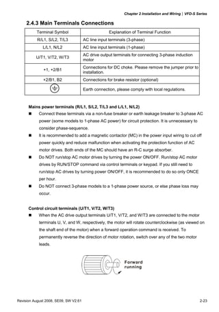
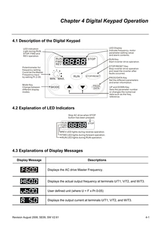
This document provides instructions for installing and operating a DELTA VFD-S Series AC motor drive. It begins with safety guidelines and an overview of the drive components and installation process. It then covers wiring, start-up procedures, operation using the digital keypad, accessing parameter settings, troubleshooting fault codes, and maintenance. Appendices provide technical specifications, dimensions of accessories, and guidelines for selecting the appropriate drive for an application.