Downloaded 155 times

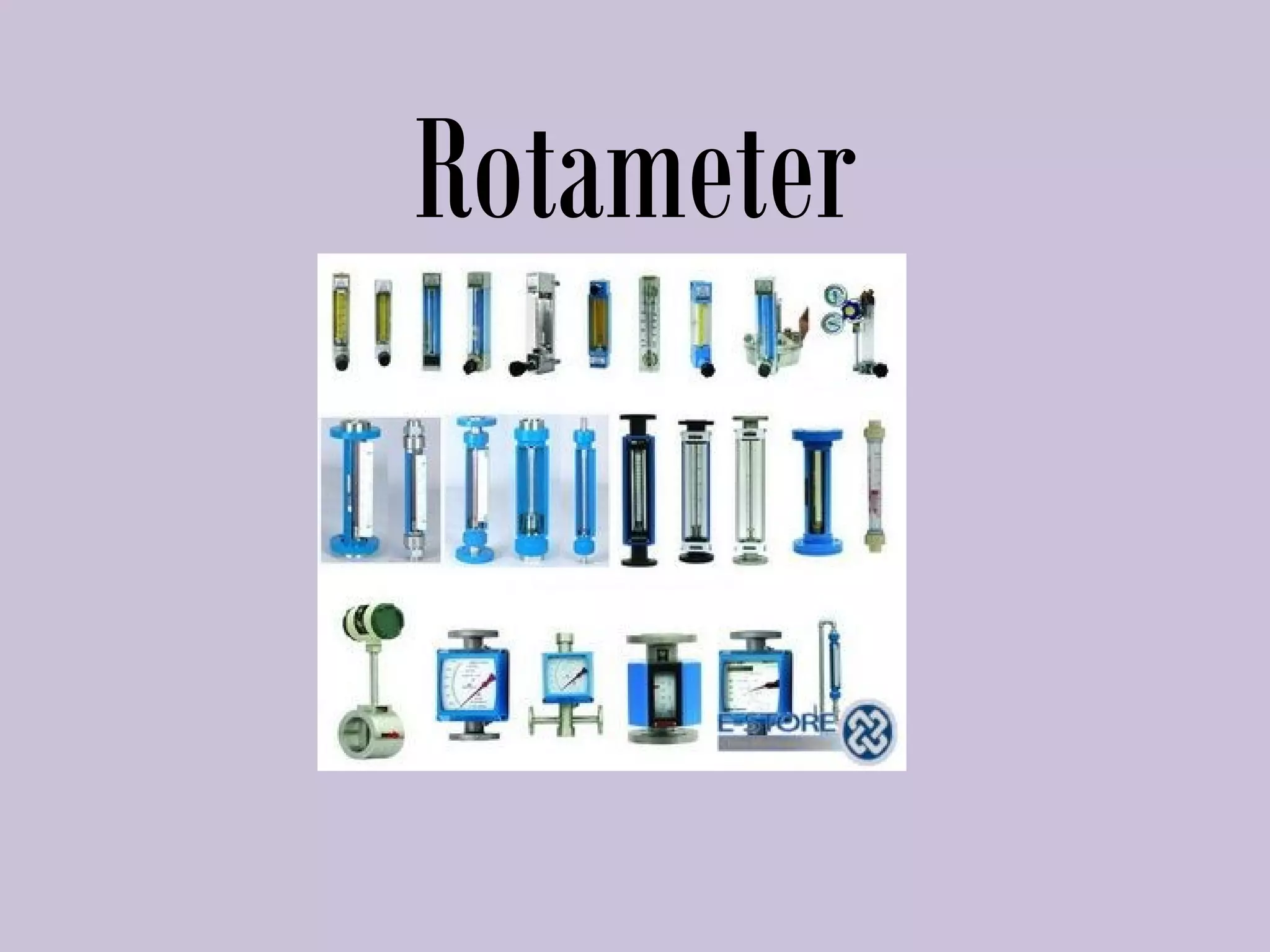
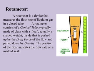
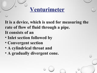
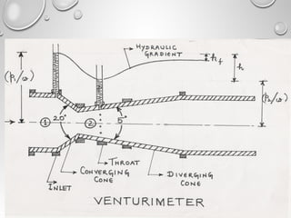
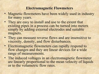
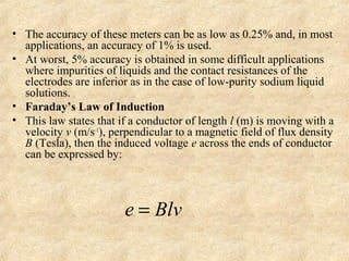
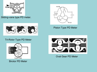


A rotameter is a flow measurement device consisting of a conical glass tube and a float, which indicates the flow rate based on its position. It requires no external power, is easy to manufacture, and operates linearly with flow rate changes. Other flow measurement devices discussed include venturimeters, electromagnetic flowmeters, and positive displacement flowmeters, each with unique working principles and applications.


