Downloaded 241 times


![Pitot tube with differential
manometer
Here,
V1 = Cv 2𝑔ℎ
h = x[
⍴ 𝐻𝑔
⍴ 𝑝𝑖𝑝𝑒
- 1]
X = Differential manometer reading in
mm of mercury
⍴ 𝑝𝑖𝑝𝑒 = Density of liquid flow through
pipe](https://image.slidesharecdn.com/bff-151011112548-lva1-app6892/85/fluid-flow-measuring-instruments-15-320.jpg)
![Pitot static tube
h = x[
⍴ 𝐻𝑔
⍴ 𝑝𝑖𝑝𝑒
- 1]
h in meter of liquid flow in channel or
through pipe](https://image.slidesharecdn.com/bff-151011112548-lva1-app6892/85/fluid-flow-measuring-instruments-16-320.jpg)


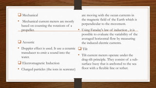

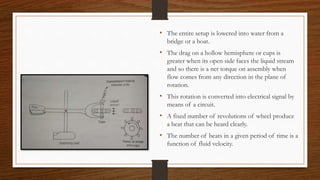

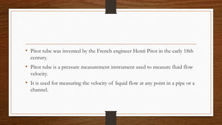
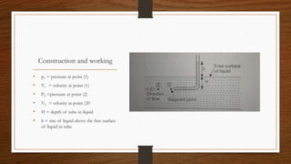
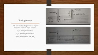
This document provides information about two instruments used to measure fluid flow: the Pitot tube and current meter. It describes the Pitot tube's invention, working principle, construction, types, and applications for measuring flow velocity. The current meter works by counting the rotations of a propeller placed in flowing water. It can also use acoustic Doppler effects, electromagnetic induction, or operate under drag-tilt principles. Both instruments are used to measure liquid flow velocities in pipes, channels, rivers, and oceans.


