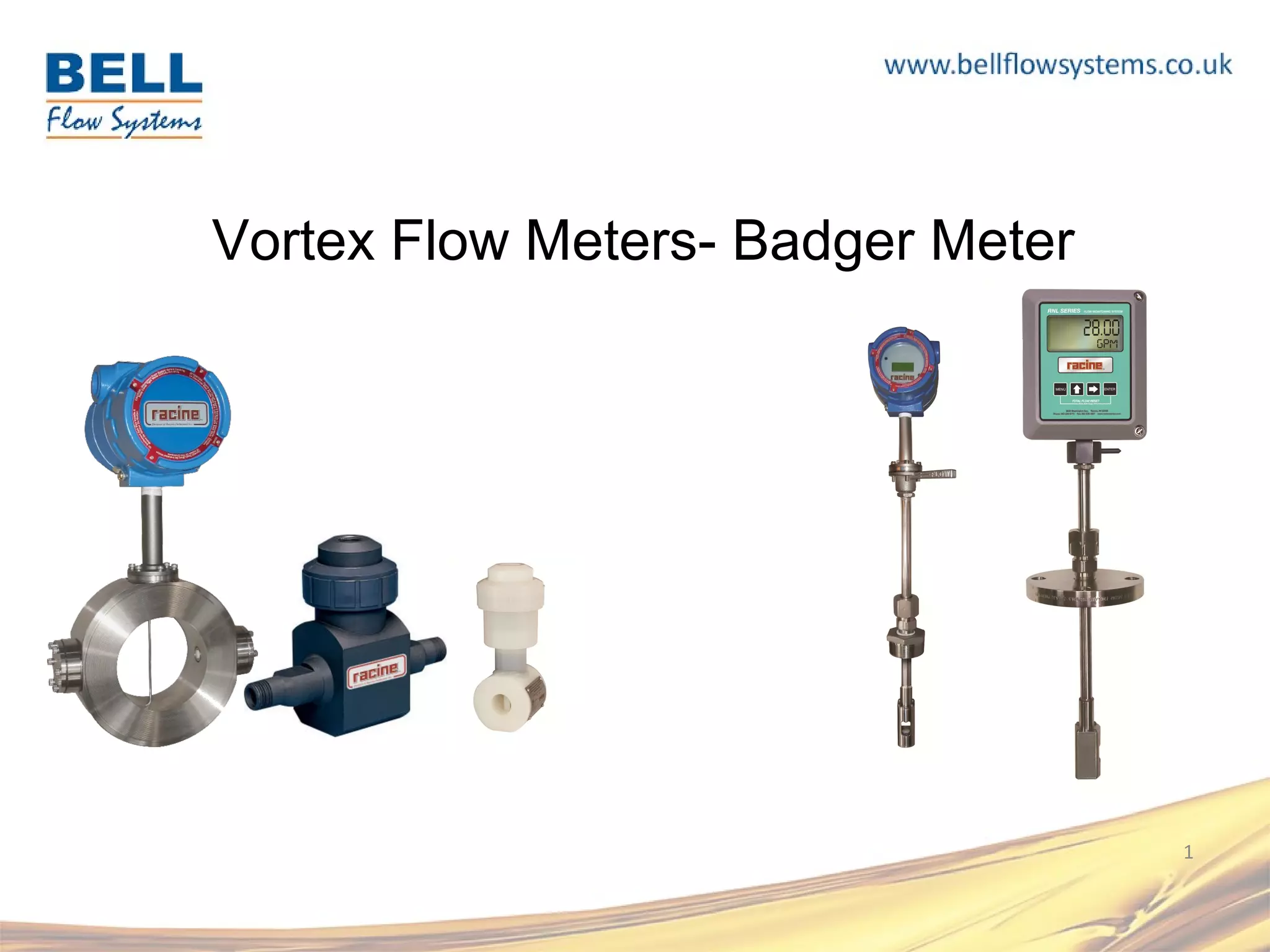
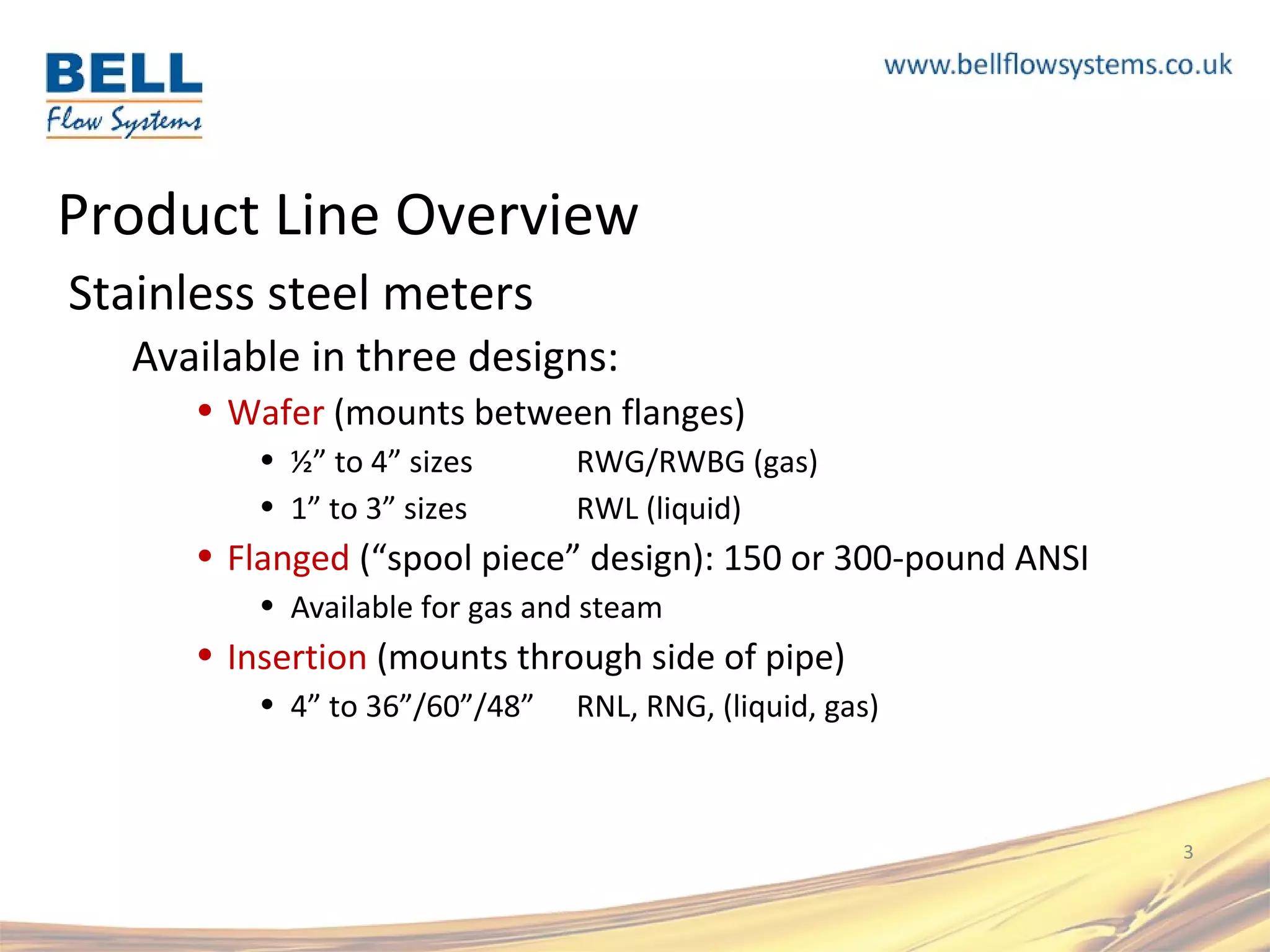
1 
Vortex Flow Meters- Badger Meter
Product Line Overview 
• Vortex-shedding technology 
• Comprised of two main product lines: 
• Stainless steel meters, liquids, gases 
• Unique combination of ultrasonic + vortex technologies 
• Thermoplastic meters; for liquids only 
• Traditional piezoelectric vortex-shedding technology 
• New ultrasonic version; RFI plans to complete the R&D 
in 2012 
2
Product Line Overview 
Stainless steel meters 
Available in three designs: 
• Wafer (mounts between flanges) 
• ½” to 4” sizes RWG/RWBG (gas) 
• 1” to 3” sizes RWL (liquid) 
• Flanged (“spool piece” design): 150 or 300-pound ANSI 
• Available for gas and steam 
• Insertion (mounts through side of pipe) 
• 4” to 36”/60”/48” RNL, RNG, (liquid, gas) 
3
Primary Markets 
Industrial Gas 
Measurement 
Natural Gas/ Biogas 
Semiconductor
Vortex Shedding Technology - Ultrasonic 
• The principle operates by looking at pressure 
fluctuations, the meter uses ultrasonic 
technology: 
• The meter transmits an ultrasonic beam through 
this vortex pattern. As vortices are shed, the 
carrier wave of the ultrasonic signal is modified. 
The change in the carrier wave occurs in 
proportion to the number of vortices shed. 
• The vortices are counted, and this value is 
converted into fluid velocity. 
• This technology is used by the Racine Vortex 
stainless steel meters. 
5
Vortex SS meter advantages 
• Ultrasonic component is unique in 
industry 
• Smallest strut (“bluff bar”) in industry 
– High sensitivity 
– High turndown ratios 
(70:1 – insertion gas meter) 
– Very low pressure drop: near zero 
• No moving parts 
• For the most part, Vortex gas flow meters 
do not have a minimum pressure 
requirement. 
Racine Vortex and Rosemount 
1.5” wafer meters 6
Product Line Overview - Wafer 
RWG 
• Wafer style vortex-shedding flow meter 
• Average turndown ratio 40:1 
• Maximum pressure 250 psig (17 bar) 
• Maximum temperature 300 °F (150 °C) 
• Sizes: ½”, 1”, 1-1/2”, 2”, 3”, 4” 
RWBG 
• Optimized for “biogas” applications: 
(CH4 + CO2) 
• Less sensitive to moisture content in gas 
7
Product Line Overview - Flanged 
RWG option 
• Flange spool piece 
• 316 stainless steel construction 
• 150 or 300-pound ANSI RF flanges 
• Can be fabricated to customer-defined length 
• Ported (1/4” NPT) for pressure sensor 
• Custom configurations possible 
8
Product Line Overview - Insertion 
RNG Insertion Meter 
• 70:1 turndown ratio 
• Pipe sizes from 4” to 60” 
• Mounts via 2” NPT, 2” ANSI or DN50 flange 
Options: 
• Hot tap kit w/ ball valve: insert or remove without 
process shut down 
• Teflon-coated wetted components 
• Hastelloy-C wetted components 
9
Vortex meters specifications 
Racine Vortex and Rosemount 
1.5” wafer meters 10
RWG / RNG Gas Meters: common features 
• Gas meters are calibrated on an advanced air flow test 
stand; sonic nozzles (master meters) are calibrated at 
outside laboratory 
• HART Communications protocol 
• ±1% of reading accuracy 
• 2 FPS, 0.6m/s minimum velocity 
• Loop-powered: 24 VDC input power, 4-20 mA output 
• HART utility PC software application for field 
configuration 
11
RWG and RNG Gas Meters: common options 
• Digital display of primary variable 
• O-ring materials to meet material compatibility 
requirements 
• Remote-mount electronics option 
• ATEX hazardous area certification ATEX Ex II 2G ib IIB T4 
• Temperature compensation of flow rate, via internal RTD 
This option also includes the ability to accept the 4-20 mA signal 
from an external pressure sensor, for a fully compensated, true 
mass flow reading 
12
Product Line Overview - Wafer 
RWL 
• Wafer style vortex-shedding flow meter 
• Average turndown ratio 10:1 
• Maximum dependent on pressure 300 psig 
(20 bar) 
• Maximum temperature 300 °F (150 °C) 
• Sizes: 1”, 1-1/2”, 2”, 3” 
13
Product Line Overview - Insertion 
RNL Insertion Meter 
• 10:1 turndown ratio 
• Temperature max 148 °C 
• Stem length 12” to 36” 
• Mounts via 2” NPT, 2” ANSI or DN50 flange 
• Optional display version 
Options: 
• Hot tap kit w/ ball valve: insert or remove 
without process shut down 
14
Vortex meters specifications 
Racine Vortex and Rosemount 
1.5” wafer meters 15
Vortex meters specifications 
Racine Vortex and Rosemount 
1.5” wafer meters 16
RVL Series 
Thermoplastic Vortex Flow Meters
RVL Series Liquid Vortex 
• All-plastic wetted parts 
(Teflon, PVC, CPVC, PVDF, 
Polypropylene) 
• ± 1% of full scale 
• 12:1 turndown 
• 13-30 VDC input power, 3-wire 
device 
• 4-20 mA , 0-5V or pulse output 
• Wafer, Flare, Butt, NPT
RVL Series 
Low Viscosity Fluid Measurement 
• Ultra-pure water 
• Acids 
• Aggressive Chemicals 
Markets 
• Semicon 
• Pharmaceutical 
• Chemical Processing 
• Industrial 
• Replaces paddle wheels and other mechanical technologies
RVL Operating Principle 
• The initial bluff bar creates the 
vortex. 
• Vortices form alternately, from one 
side to the other causing pressure 
fluctuations. 
• These are sensed by a 
piezoelectric crystal in the second 
bluff bar. 
• The output from the meter can be 
either a pulse signal or analog.
Viscosity and Flow Range 
Weight Minimum Maximum Flow Range 
1 CST 1 12 12:1 
2 CST 2 12 6:1 
3 CST 3 12 4:1 
4 CST 4 12 3:1 
5 CST 5 12 2.4:1 
6 CST 6 12 2:1 
Viscosities above 1 cSt will raise the minimum usable flow rate – Reducing 
the meter’s effective range
Maximum Fluid Operating Pressure 
Temperature PSIG (Kpa) 
⁰F. ⁰C. PVC CPVC PVDF 
203 95 NR CF CF 
150 66 NR 63 (434) 130 (896) 
100 38 93 (641) 120 (627) 150 (1034) 
70 21 150 (1034) 150 (1034) 150 (1034)
RVL Series Liquid Flow Meter 
Class 1000 Clean room construction option: 
– No more than 1000 0.5 micron particles per cubic foot of air. 
Requirement for Semicon, Biotech and Medical 
applications.
Vortex - Material Selection 
Select the meter body material 
that is compatible for the fluid, 
ensure that the fluid does not 
contain considerable amounts of 
fibers or abrasive materials that 
will cause erosion or affect 
vortex formation.
Thank you 
+44 (0)1280 817304 sales@bellflowsystems.co.uk 
www.badgermeter.co.uk 
Bell Flow Systems are the UK representative of Badger Meter 
25

Vortex Flow Meters- Badger Meter

  • 1.
    1 Vortex FlowMeters- Badger Meter
  • 2.
    Product Line Overview • Vortex-shedding technology • Comprised of two main product lines: • Stainless steel meters, liquids, gases • Unique combination of ultrasonic + vortex technologies • Thermoplastic meters; for liquids only • Traditional piezoelectric vortex-shedding technology • New ultrasonic version; RFI plans to complete the R&D in 2012 2
  • 3.
    Product Line Overview Stainless steel meters Available in three designs: • Wafer (mounts between flanges) • ½” to 4” sizes RWG/RWBG (gas) • 1” to 3” sizes RWL (liquid) • Flanged (“spool piece” design): 150 or 300-pound ANSI • Available for gas and steam • Insertion (mounts through side of pipe) • 4” to 36”/60”/48” RNL, RNG, (liquid, gas) 3
  • 4.
    Primary Markets IndustrialGas Measurement Natural Gas/ Biogas Semiconductor
  • 5.
    Vortex Shedding Technology- Ultrasonic • The principle operates by looking at pressure fluctuations, the meter uses ultrasonic technology: • The meter transmits an ultrasonic beam through this vortex pattern. As vortices are shed, the carrier wave of the ultrasonic signal is modified. The change in the carrier wave occurs in proportion to the number of vortices shed. • The vortices are counted, and this value is converted into fluid velocity. • This technology is used by the Racine Vortex stainless steel meters. 5
  • 6.
    Vortex SS meteradvantages • Ultrasonic component is unique in industry • Smallest strut (“bluff bar”) in industry – High sensitivity – High turndown ratios (70:1 – insertion gas meter) – Very low pressure drop: near zero • No moving parts • For the most part, Vortex gas flow meters do not have a minimum pressure requirement. Racine Vortex and Rosemount 1.5” wafer meters 6
  • 7.
    Product Line Overview- Wafer RWG • Wafer style vortex-shedding flow meter • Average turndown ratio 40:1 • Maximum pressure 250 psig (17 bar) • Maximum temperature 300 °F (150 °C) • Sizes: ½”, 1”, 1-1/2”, 2”, 3”, 4” RWBG • Optimized for “biogas” applications: (CH4 + CO2) • Less sensitive to moisture content in gas 7
  • 8.
    Product Line Overview- Flanged RWG option • Flange spool piece • 316 stainless steel construction • 150 or 300-pound ANSI RF flanges • Can be fabricated to customer-defined length • Ported (1/4” NPT) for pressure sensor • Custom configurations possible 8
  • 9.
    Product Line Overview- Insertion RNG Insertion Meter • 70:1 turndown ratio • Pipe sizes from 4” to 60” • Mounts via 2” NPT, 2” ANSI or DN50 flange Options: • Hot tap kit w/ ball valve: insert or remove without process shut down • Teflon-coated wetted components • Hastelloy-C wetted components 9
  • 10.
    Vortex meters specifications Racine Vortex and Rosemount 1.5” wafer meters 10
  • 11.
    RWG / RNGGas Meters: common features • Gas meters are calibrated on an advanced air flow test stand; sonic nozzles (master meters) are calibrated at outside laboratory • HART Communications protocol • ±1% of reading accuracy • 2 FPS, 0.6m/s minimum velocity • Loop-powered: 24 VDC input power, 4-20 mA output • HART utility PC software application for field configuration 11
  • 12.
    RWG and RNGGas Meters: common options • Digital display of primary variable • O-ring materials to meet material compatibility requirements • Remote-mount electronics option • ATEX hazardous area certification ATEX Ex II 2G ib IIB T4 • Temperature compensation of flow rate, via internal RTD This option also includes the ability to accept the 4-20 mA signal from an external pressure sensor, for a fully compensated, true mass flow reading 12
  • 13.
    Product Line Overview- Wafer RWL • Wafer style vortex-shedding flow meter • Average turndown ratio 10:1 • Maximum dependent on pressure 300 psig (20 bar) • Maximum temperature 300 °F (150 °C) • Sizes: 1”, 1-1/2”, 2”, 3” 13
  • 14.
    Product Line Overview- Insertion RNL Insertion Meter • 10:1 turndown ratio • Temperature max 148 °C • Stem length 12” to 36” • Mounts via 2” NPT, 2” ANSI or DN50 flange • Optional display version Options: • Hot tap kit w/ ball valve: insert or remove without process shut down 14
  • 15.
    Vortex meters specifications Racine Vortex and Rosemount 1.5” wafer meters 15
  • 16.
    Vortex meters specifications Racine Vortex and Rosemount 1.5” wafer meters 16
  • 17.
    RVL Series ThermoplasticVortex Flow Meters
  • 18.
    RVL Series LiquidVortex • All-plastic wetted parts (Teflon, PVC, CPVC, PVDF, Polypropylene) • ± 1% of full scale • 12:1 turndown • 13-30 VDC input power, 3-wire device • 4-20 mA , 0-5V or pulse output • Wafer, Flare, Butt, NPT
  • 19.
    RVL Series LowViscosity Fluid Measurement • Ultra-pure water • Acids • Aggressive Chemicals Markets • Semicon • Pharmaceutical • Chemical Processing • Industrial • Replaces paddle wheels and other mechanical technologies
  • 20.
    RVL Operating Principle • The initial bluff bar creates the vortex. • Vortices form alternately, from one side to the other causing pressure fluctuations. • These are sensed by a piezoelectric crystal in the second bluff bar. • The output from the meter can be either a pulse signal or analog.
  • 21.
    Viscosity and FlowRange Weight Minimum Maximum Flow Range 1 CST 1 12 12:1 2 CST 2 12 6:1 3 CST 3 12 4:1 4 CST 4 12 3:1 5 CST 5 12 2.4:1 6 CST 6 12 2:1 Viscosities above 1 cSt will raise the minimum usable flow rate – Reducing the meter’s effective range
  • 22.
    Maximum Fluid OperatingPressure Temperature PSIG (Kpa) ⁰F. ⁰C. PVC CPVC PVDF 203 95 NR CF CF 150 66 NR 63 (434) 130 (896) 100 38 93 (641) 120 (627) 150 (1034) 70 21 150 (1034) 150 (1034) 150 (1034)
  • 23.
    RVL Series LiquidFlow Meter Class 1000 Clean room construction option: – No more than 1000 0.5 micron particles per cubic foot of air. Requirement for Semicon, Biotech and Medical applications.
  • 24.
    Vortex - MaterialSelection Select the meter body material that is compatible for the fluid, ensure that the fluid does not contain considerable amounts of fibers or abrasive materials that will cause erosion or affect vortex formation.
  • 25.
    Thank you +44(0)1280 817304 sales@bellflowsystems.co.uk www.badgermeter.co.uk Bell Flow Systems are the UK representative of Badger Meter 25

Editor's Notes

  • #4 In the model numbers, we designate wafers with a “w”, and insertion meters with an “n”. Gas insertion to 60” (in fact we’ve done a 72” meter); and steam insertion meters to 48” In the next several slides we’ll focus mainly on gas and liquid stainless steel meters, and we’ll return to steam and thermoplastic meters later this afternoon.
  • #5 The Vortex product line mix brings together a number of discrete market opportunities, ranging from semiconductor capital equipment, to boiler, to methane gas in a landfill. We will try to touch on all of these, despite the fact that many of you come in with a particular focus.
  • #6 So we can see, one of the key benefits with ultrasonic is that you don’t need to generate pressure fluctuations, therefore you don’t need a large strut.
  • #7 To our knowledge there are no major manufacturers utilizing an ultrasonic component in their vortex meters. Exception is Hontzsch (Germany). Racine Vortex meters do have a minimum velocity requirement, but not a minimum pressure requirement. Bluff bar comparison – the “other” meter is an actual trace of a Rosemount standard vortex meter.
  • #8 The RWBG incorporates a different transducer material and design that is more effective in moist conditions. Submersion or a complete coating of the transducers will impair the meter performance however.
  • #9 Custom lengths and configurations: you will see on our test stand that we’re using adjustable-length connectors to mount the wafers, which allows for full calibration over a large spool piece range. Because of our work with Preso, our engineering team is highly adept at customizing spool pieces for unique customer requirements
  • #10 A compression fitting is utilized to keep the meter from rotating or sliding out of the optimal installed position The Teflon coating is an added protection against aggressive gas mixtures, such as those containing acids. However physical damage to the coating will render the protection ineffective – the best protection will be to use Hastelloy C
  • #12 Master meters calibrated at CEESI (Colorado)
  • #14 The RWBG incorporates a different transducer material and design that is more effective in moist conditions. Submersion or a complete coating of the transducers will impair the meter performance however.
  • #15 A compression fitting is utilized to keep the meter from rotating or sliding out of the optimal installed position The Teflon coating is an added protection against aggressive gas mixtures, such as those containing acids. However physical damage to the coating will render the protection ineffective – the best protection will be to use Hastelloy C