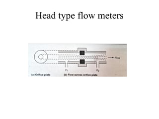
Orifice plate flowmeters
• It has a metal disk with a concentric hole as shown
in the previous slide
• It is the simplest and widely used device
• It is cheaper and widely used
Working:
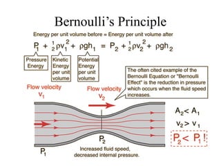
Based on Bernoulli's principle, the change in pressure
at P2 with respect to P1 is directly proportional to the
change in velocity. So by measuring the change in
pressure we can calculate the flow rate
8.
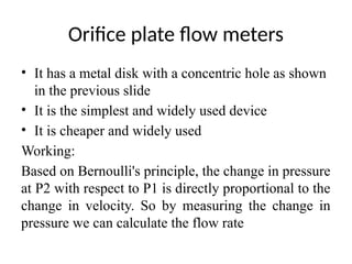
Cntd..
• The flowrate is indicated in m/s, if we need
volume we have to multiply flow rate and area
of cross section i.e.,
• Disadvantages
– The area of the hole through which the fluid passes
may get widened over time and usage
– The bubbles or vapours building up behind the
plate may lead to measurement errors
9.
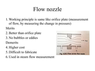
Flow nozzle
1. Workingprinciple is same like orifice plate (measurement
of flow, by measuring the change in pressure)
Merits
2. Better than orifice plate
3. No bubbles or eddies
Demerits
4. Higher cost
5. Difficult to fabricate
6. Used in steam flow measurement
10.
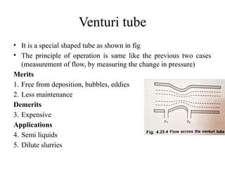
Venturi tube
• Itis a special shaped tube as shown in fig
• The principle of operation is same like the previous two cases
(measurement of flow, by measuring the change in pressure)
Merits
1. Free from deposition, bubbles, eddies
2. Less maintenance
Demerits
3. Expensive
Applications
4. Semi liquids
5. Dilute slurries
11.
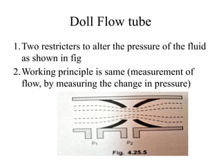
Doll Flow tube
1.Tworestricters to alter the pressure of the fluid
as shown in fig
2.Working principle is same (measurement of
flow, by measuring the change in pressure)
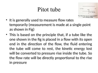
Pitot tube
• Itis generally used to measure flow rates
temporarily (measurement is made at a single point
as shown in Fig)
• This is based on the principle that, if a tube like the
one shown in the fig is placed in a flow with its open
end in the direction of the flow, the fluid entering
the tube will come to rest, the kinetic energy lost
will be converted to pressure rise inside the tube. So
the flow rate will be directly proportional to the rise
in pressure
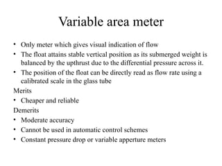
Variable area meter
•Only meter which gives visual indication of flow
• The float attains stable vertical position as its submerged weight is
balanced by the upthrust due to the differential pressure across it.
• The position of the float can be directly read as flow rate using a
calibrated scale in the glass tube
Merits
• Cheaper and reliable
Demerits
• Moderate accuracy
• Cannot be used in automatic control schemes
• Constant pressure drop or variable apperture meters
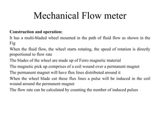
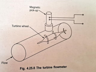
Mechanical Flow meter
Constructionand operation:
It has a multi-bladed wheel mounted in the path of fluid flow as shown in the
Fig
When the fluid flow, the wheel starts rotating, the speed of rotation is directly
proportional to flow rate
The blades of the wheel are made up of Ferro magnetic material
The magnetic pick up comprises of a coil wound over a permanent magnet
The permanent magnet will have flux lines distributed around it
When the wheel blade cut these flux lines a pulse will be induced in the coil
wound around the permanent magnet
The flow rate can be calculated by counting the number of induced pulses
19.
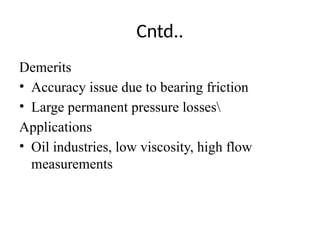
Cntd..
Demerits
• Accuracy issuedue to bearing friction
• Large permanent pressure losses
Applications
• Oil industries, low viscosity, high flow
measurements
20.
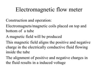
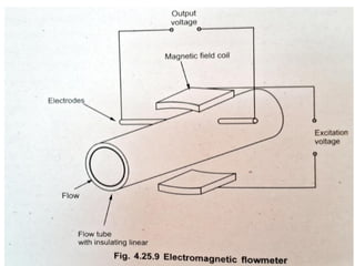
Electromagnetic flow meter
Constructionand operation:
Electromagnets/magnetic coils placed on top and
bottom of a tube
A magnetic field will be produced
This magnetic field aligns the positive and negative
charge in the electrically conductive fluid flowing
inside the tube
The alignment of positive and negative charges in
the fluid results in a induced voltage
21.
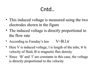
Cntd..
• This inducedvoltage is measured using the two
electrodes shown in the figure
• The induced voltage is directly proportional to
the flow rate
• According to Faraday’s law V=B.l.v
• Here V is induced voltage, l is length of the tube, v is
velocity of fluid, B is magnetic flux density
• Since ‘B’ and ‘l’ are constants in this case, the voltage
is directly proportional to the velocity
23.
Cntd..
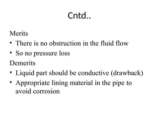
Merits
• There isno obstruction in the fluid flow
• So no pressure loss
Demerits
• Liquid part should be conductive (drawback)
• Appropriate lining material in the pipe to
avoid corrosion
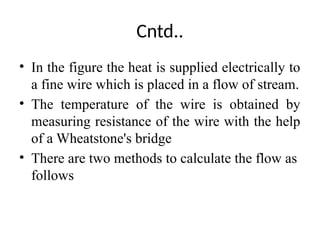
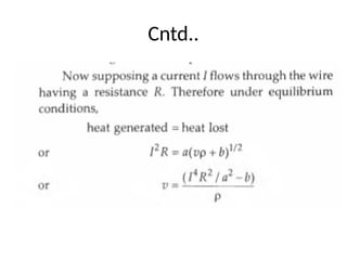
Cntd..
• Anemometer isa device used to measure flow of
fluid/air
• Hot wire anemometer is based on the principle of
heat transfer
• The principle is when a fluid flow over a heated
surface, the heat in the surface will be transferred to
the fluid. This reduces temperature of the surface
• The rate of change in temperature defines the flow
rate.
26.
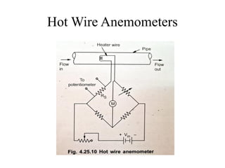
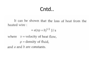
Cntd..
• In thefigure the heat is supplied electrically to
a fine wire which is placed in a flow of stream.
• The temperature of the wire is obtained by
measuring resistance of the wire with the help
of a Wheatstone's bridge
• There are two methods to calculate the flow as
follows
27.
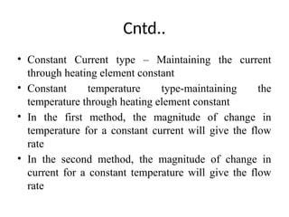
Cntd..
• Constant Currenttype – Maintaining the current
through heating element constant
• Constant temperature type-maintaining the
temperature through heating element constant
• In the first method, the magnitude of change in
temperature for a constant current will give the flow
rate
• In the second method, the magnitude of change in
current for a constant temperature will give the flow
rate
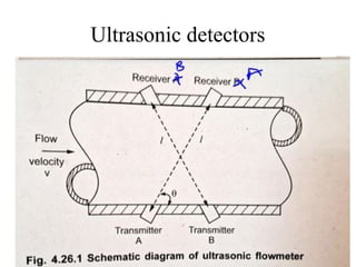
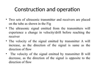
Construction and operation
•Two sets of ultrasonic transmitter and receivers are placed
on the tube as shown in the Fig
• The ultrasonic signal emitted from the transmitters will
experience a change in velocity/drift before reaching the
receiver
• The velocity of the signal emitted by transmitter A will
increase, as the direction of the signal is same as the
direction of flow
• The velocity of the signal emitted by transmitter B will
decrease, as the direction of the signal is opposite to the
direction of flow
33.
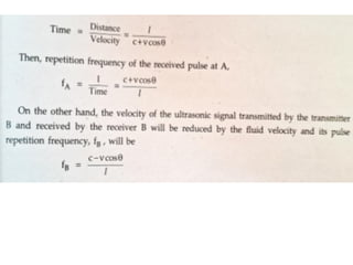
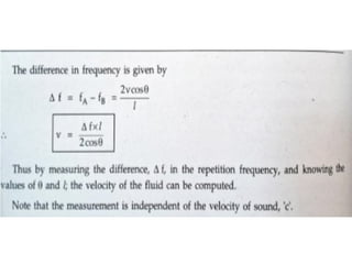
Cntd..
• The timeis calculated based on the velocity
• The frequency is calculated from time
• The difference in frequency will be
proportional to the length and velocity
• Length being constant, the velocity can be
determined by measuring the change in
frequency as derived below
36.
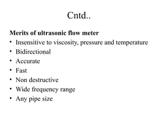
Cntd..
Merits of ultrasonicflow meter
• Insensitive to viscosity, pressure and temperature
• Bidirectional
• Accurate
• Fast
• Non destructive
• Wide frequency range
• Any pipe size