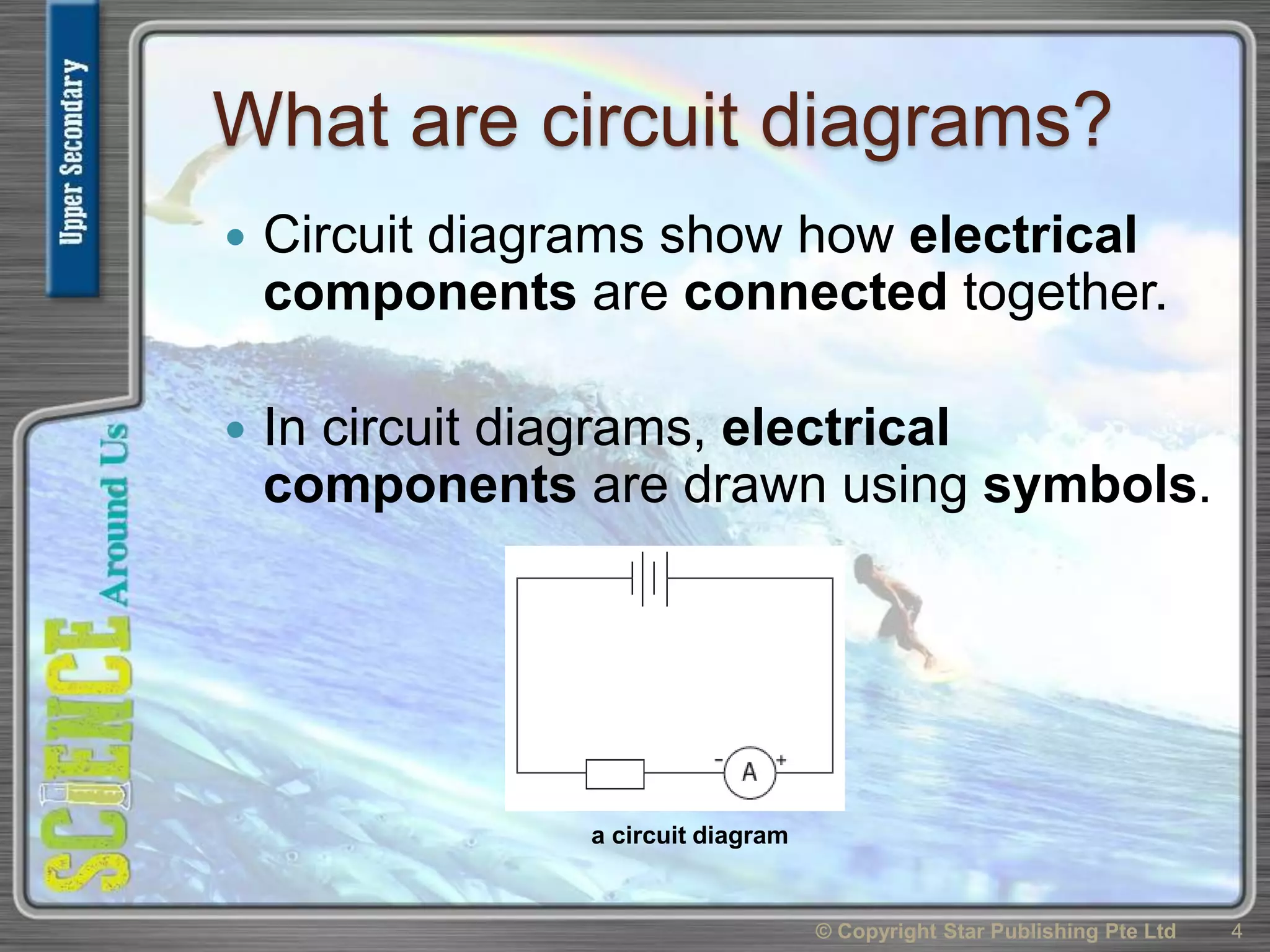
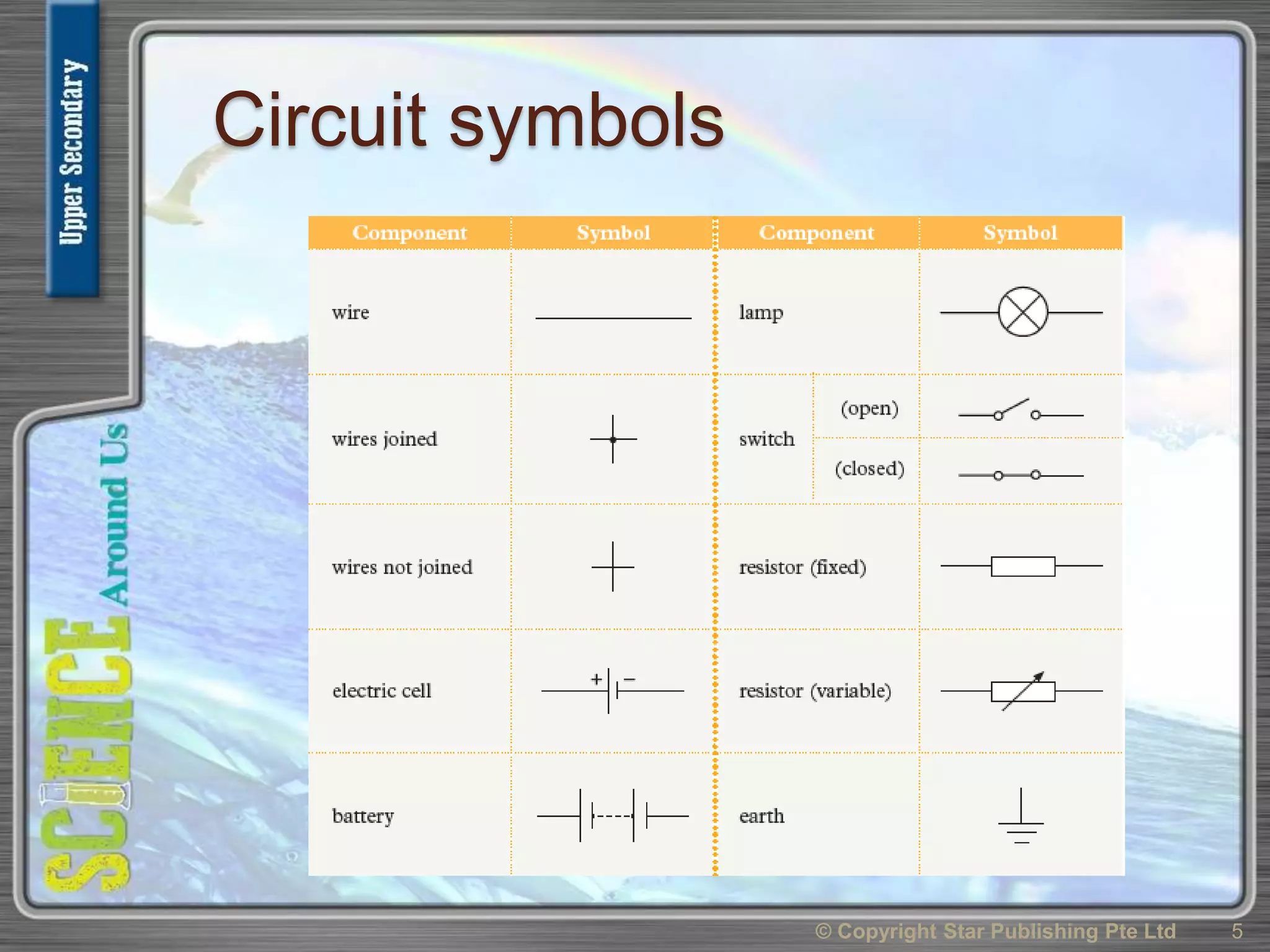
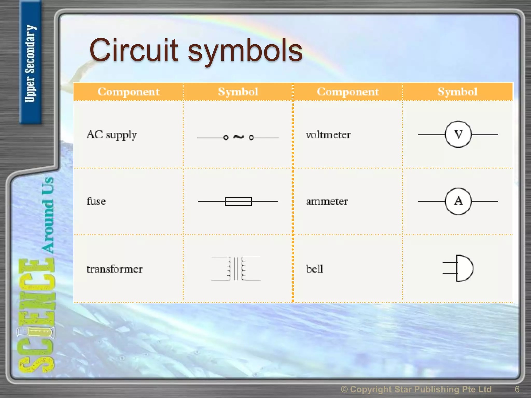
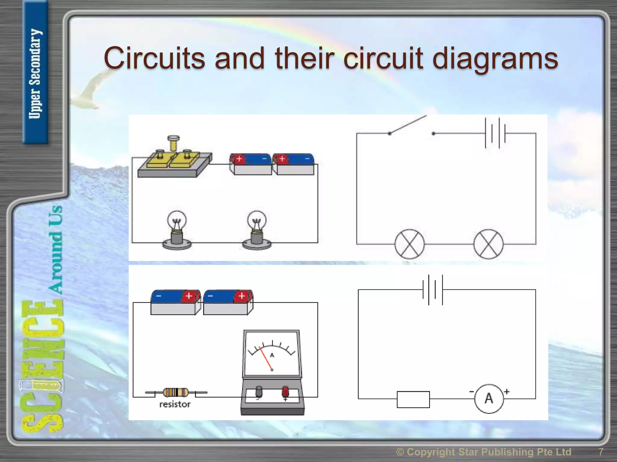
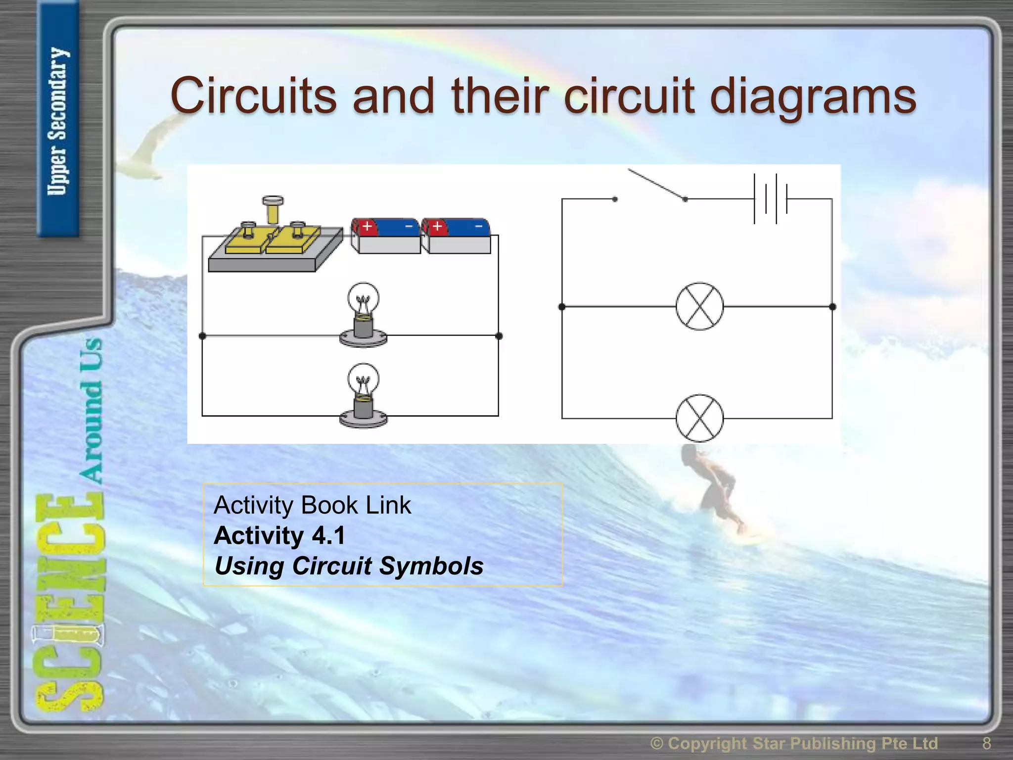
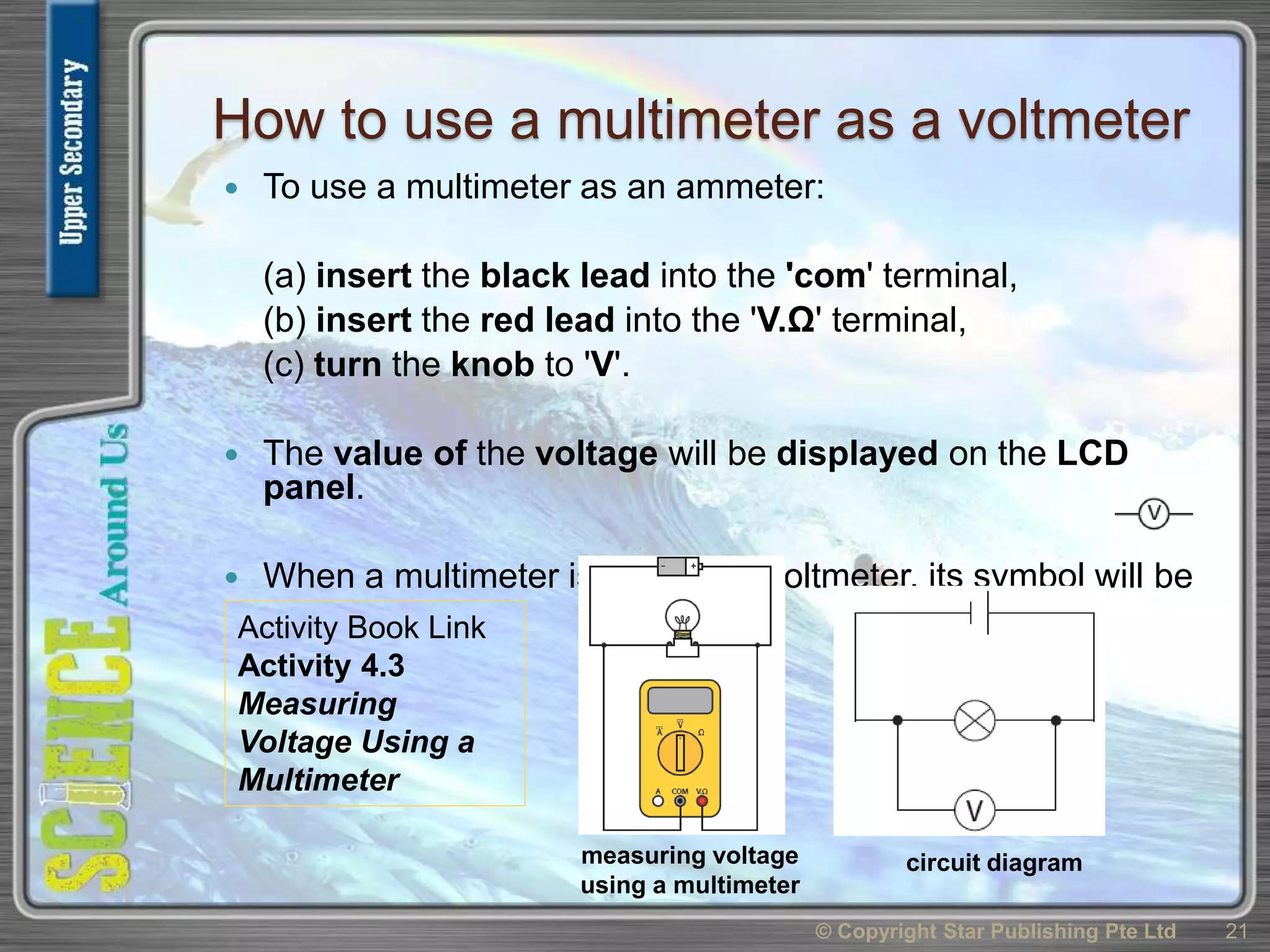
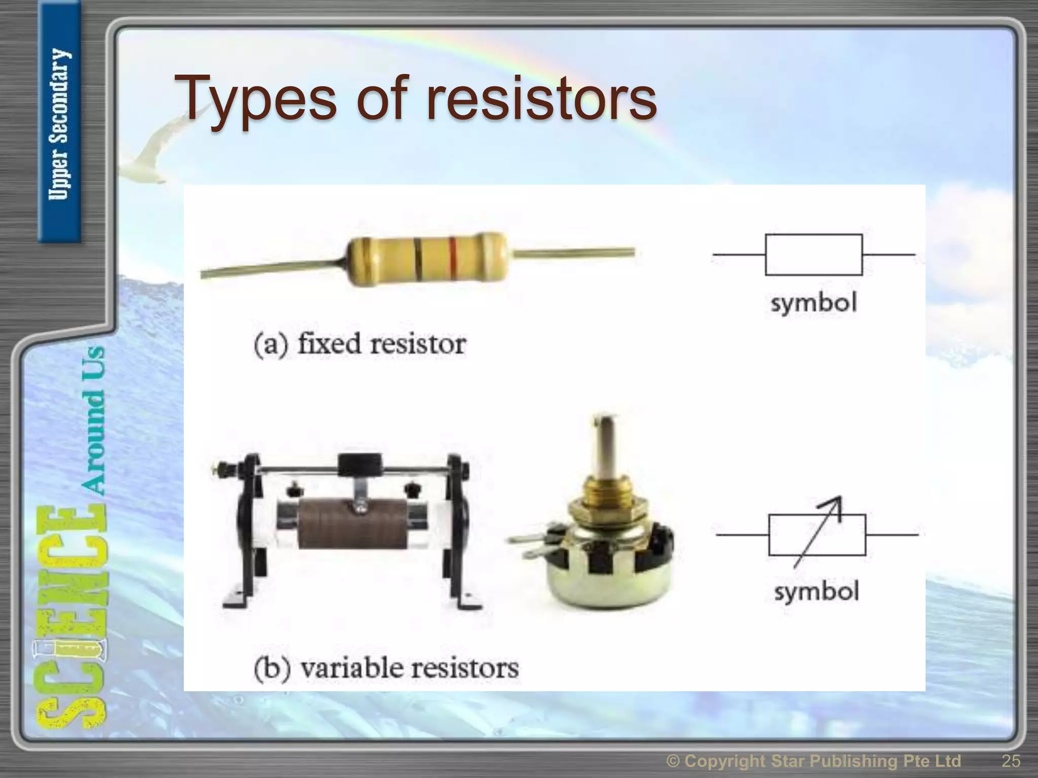
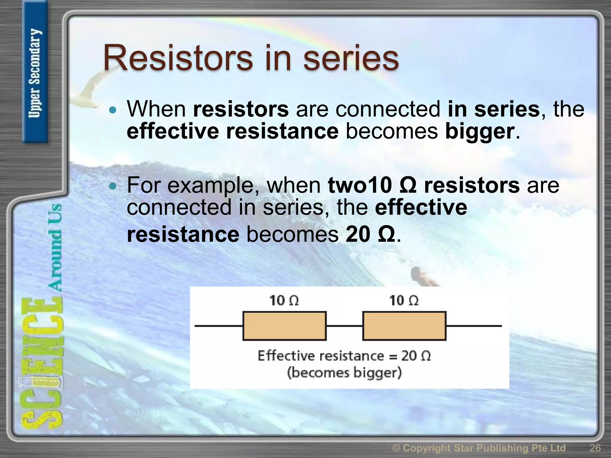
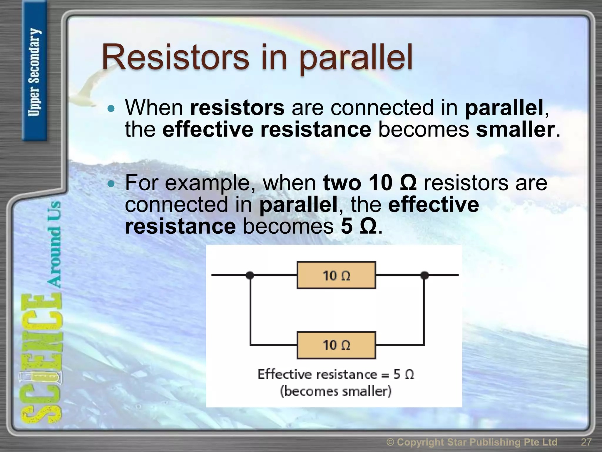
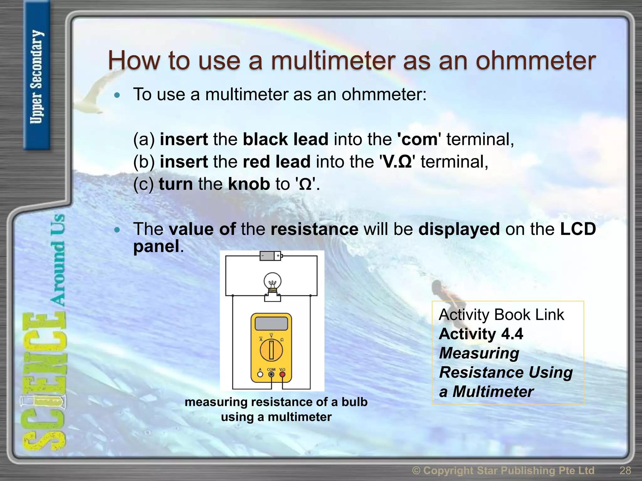
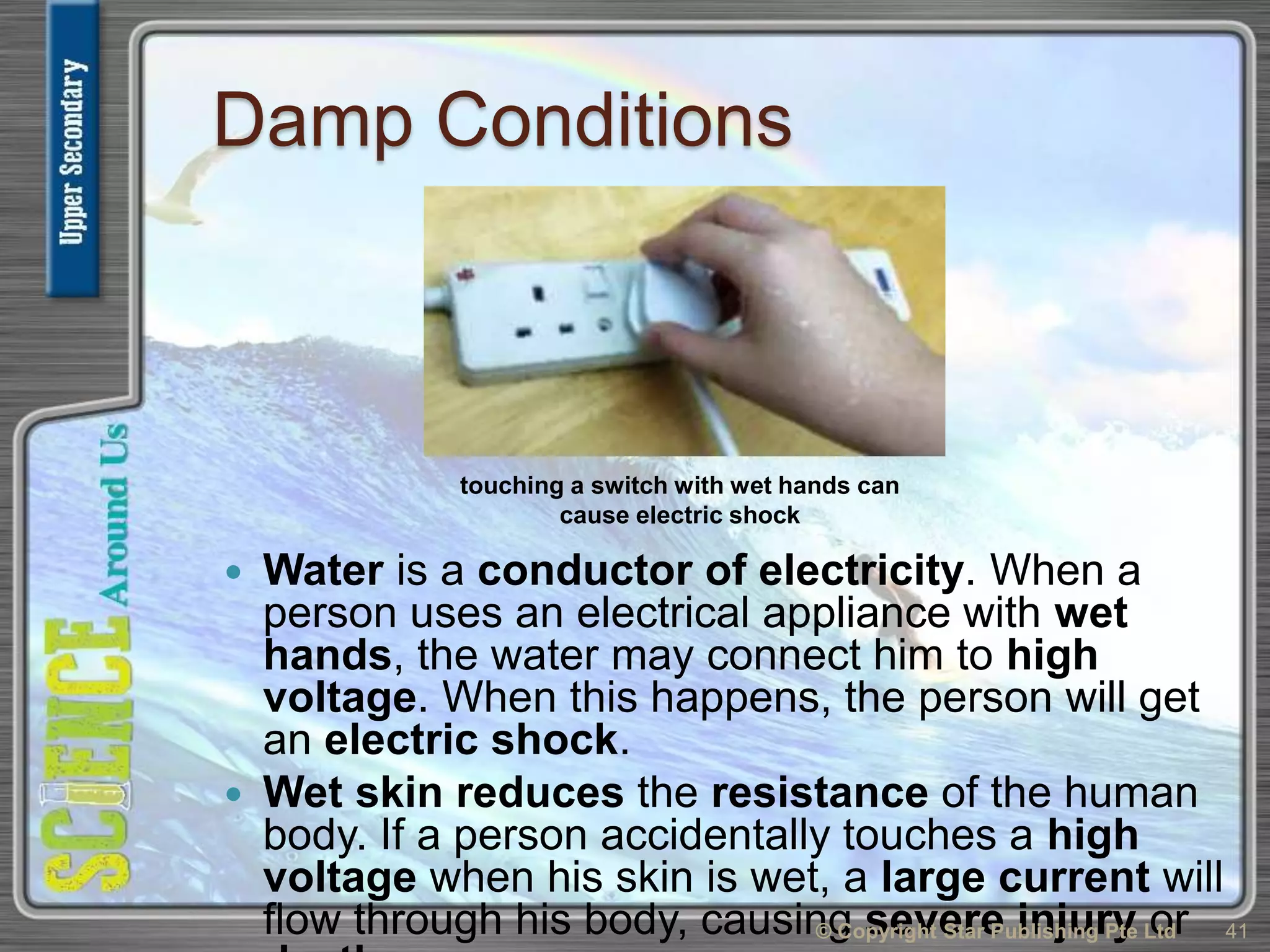
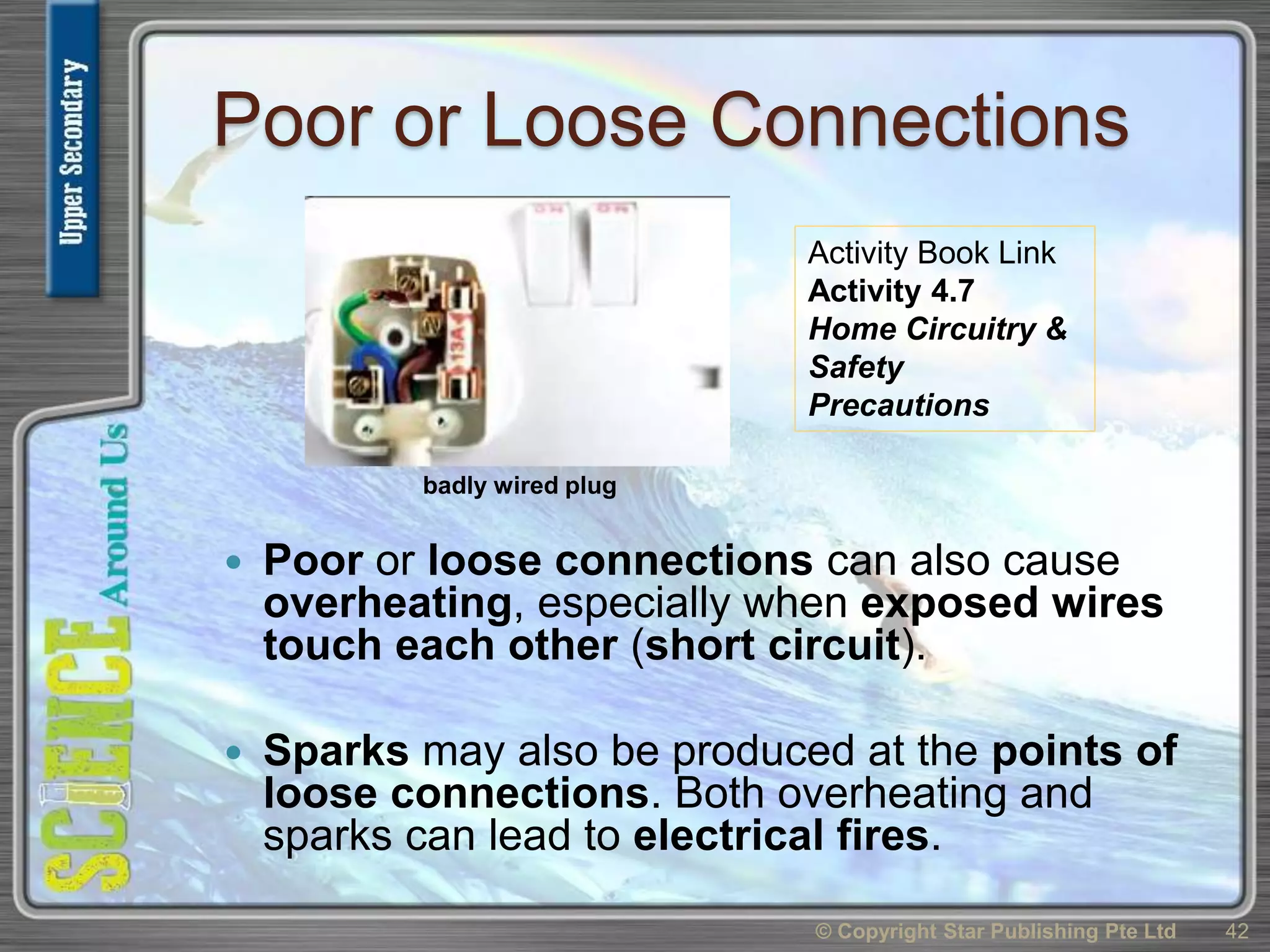
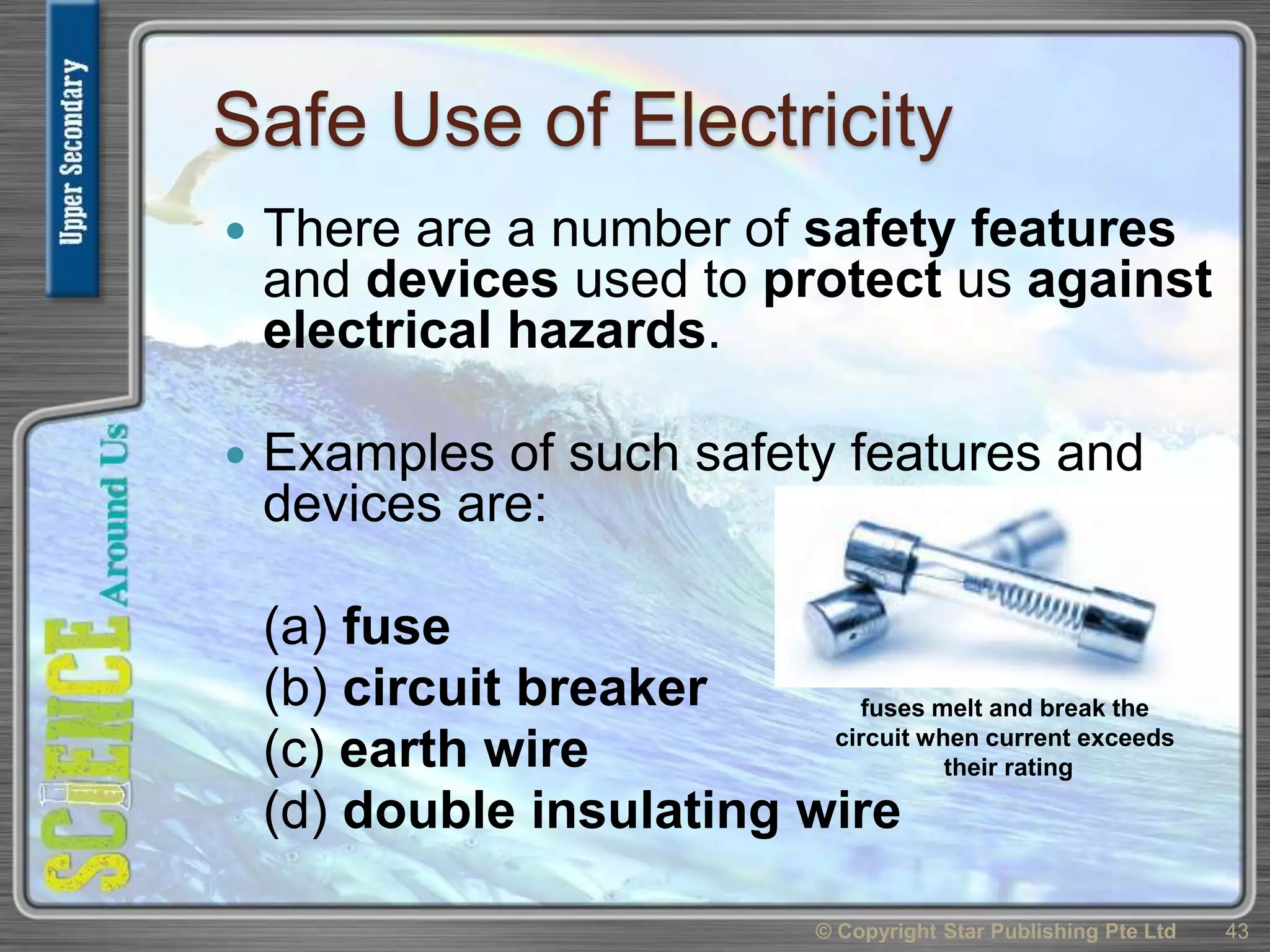
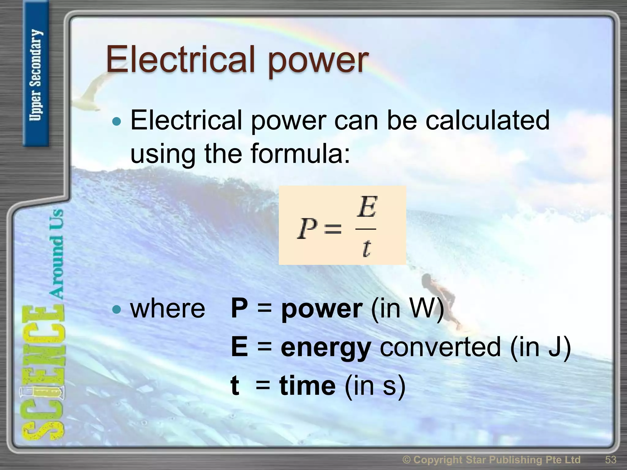
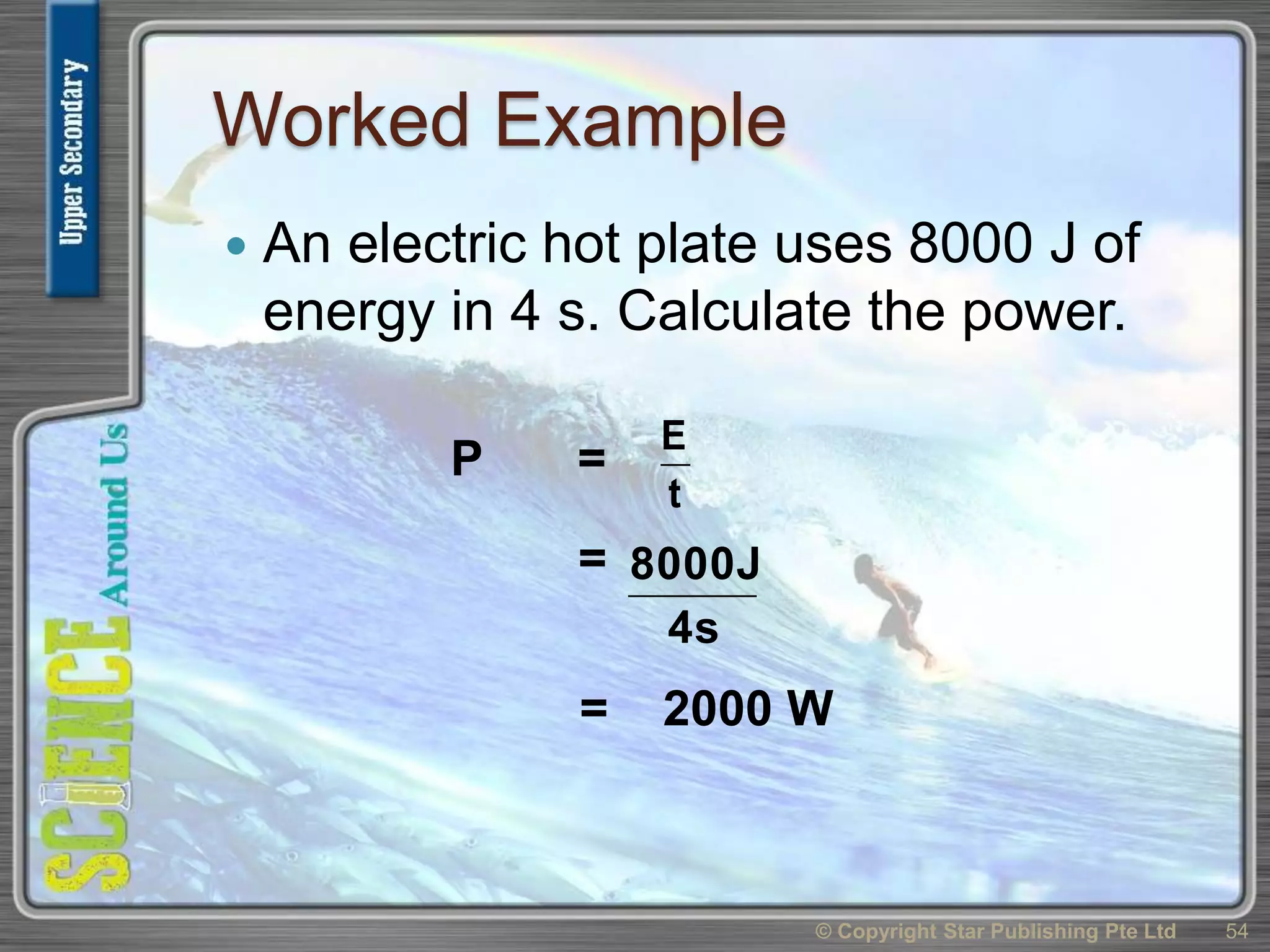
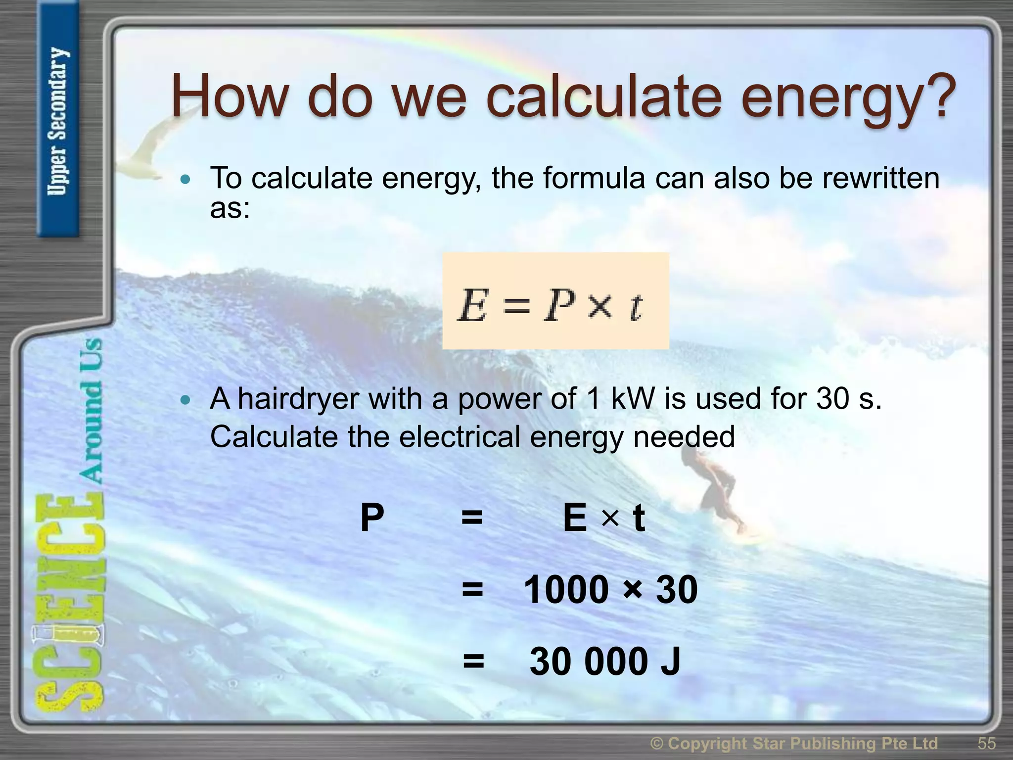
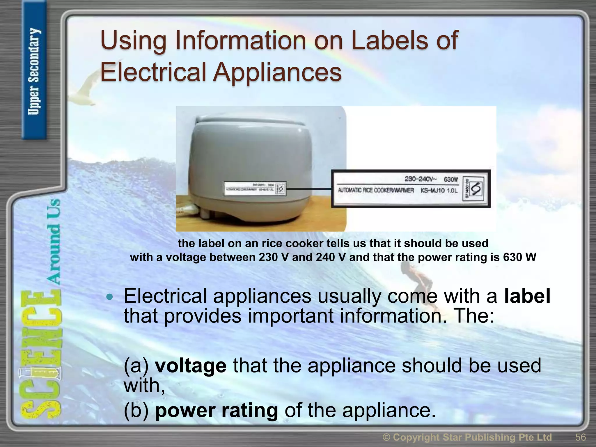
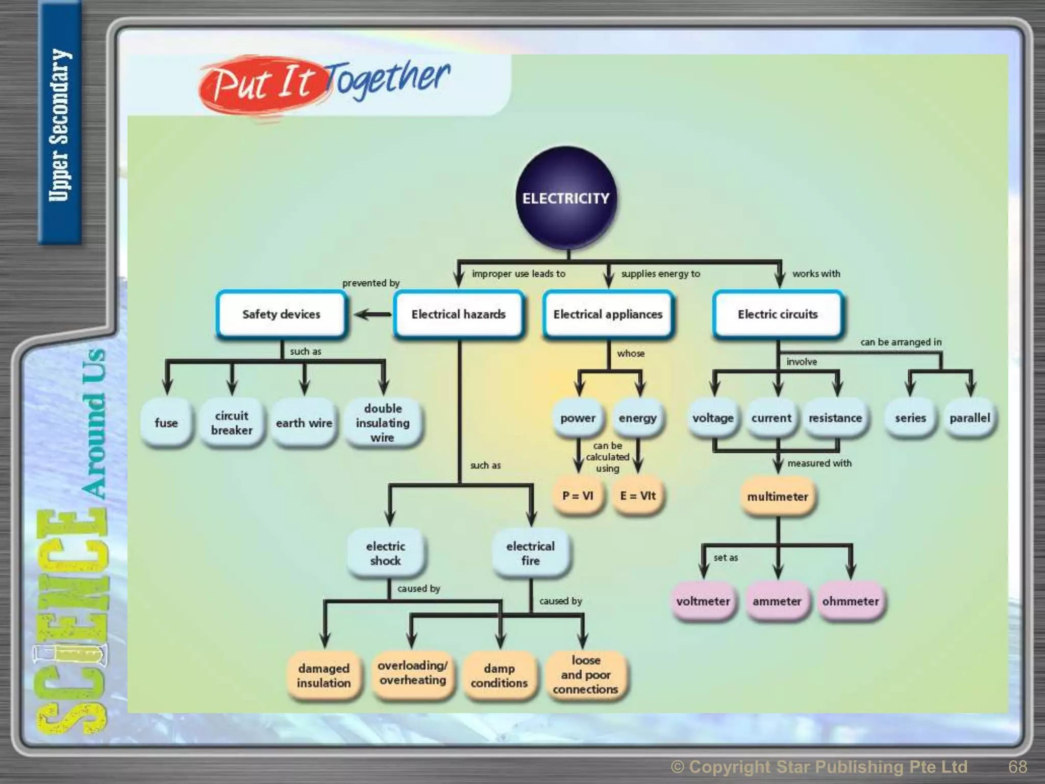
Module 4:
Gadgets Work Wonders (II)
Chapter 4 Electricity
1© Copyright Star Publishing Pte Ltd
Chapter 4 Electricity
4.1 How can electric circuit symbols be
used to draw circuit diagrams?
4.2 How are current, voltage and
resistance measured?
4.3 What are the differences between
series and parallel circuits?
4.4 What are the applications of series and
parallel circuits in daily life?
4.5 How do we use electricity safely?
4.6 How can information on electric power
be used?
2© Copyright Star Publishing Pte Ltd
Objectives
 Draw simple series and parallel
circuits for daily applications (e.g.
table lamps use series circuits, ceiling
lamps use parallel circuits)
 Label and interpret circuit diagrams
which include cells, switches, resistors
(fixed and variable),
 voltmeters, ammeters, bells, bulbs,
lamps and fuses
3© Copyright Star Publishing Pte Ltd
What are circuit diagrams?
 Circuit diagrams show how electrical
components are connected together.
 In circuit diagrams, electrical
components are drawn using symbols.
© Copyright Star Publishing Pte Ltd 4
a circuit diagram
Circuit symbols
© Copyright Star Publishing Pte Ltd 5
Circuit symbols
© Copyright Star Publishing Pte Ltd 6
Circuits and their circuit diagrams
© Copyright Star Publishing Pte Ltd 7
Circuits and their circuit diagrams
© Copyright Star Publishing Pte Ltd 8
Activity Book Link
Activity 4.1
Using Circuit Symbols
Chapter 4 Electricity
4.1 How can electric circuit symbols be
used to draw circuit diagrams?
4.2 How are current, voltage and
resistance measured?
4.3 What are the differences between
series and parallel circuits?
4.4 What are the applications of series and
parallel circuits in daily life?
4.5 How do we use electricity safely?
4.6 How can information on electric power
be used?
9© Copyright Star Publishing Pte Ltd
Objectives
 Measure current, voltage and
resistance using a multimeter
 State that a voltage is required to
cause a current flow
 State that the effective resistance
increases when in series circuits
 State that the effective resistance
decreases when in parallel circuit
10© Copyright Star Publishing Pte Ltd
Current
 In the circuit, the bulb
lights up because
there is an electric
current flowing in the
closed circuit.
 Conventionally,
current is described
as flowing from the
positive terminal of
a battery to the
negative terminal.
© Copyright Star Publishing Pte Ltd 11
current flows in a closed
circuit
What is current?
 Electric current is due to tiny electric
charges flowing in the circuit.
 When the electric charges are flowing
at a fast rate, the current will be big.
 Therefore, current is the rate of flow
of electric charge.
© Copyright Star Publishing Pte Ltd 12
Symbol and SI unit of current
 The symbol for current is I.
 The SI unit of current is the ampere (A).
 A current of 2 amperes is written as I = 2 A.
 A smaller unit of current is the milliampere (mA)
where:
© Copyright Star Publishing Pte Ltd 13
How do we measure current?
 Current can be measured using an
ammeter connected in series.
© Copyright Star Publishing Pte Ltd 14
current can be measured using an ammeter
circuit diagram
Measuring current
 Besides the conventional type of ammeter,
another instrument called the multimeter can
be used as an ammeter to measure current.
© Copyright Star Publishing Pte Ltd 15
a multimeter
How to use a multimeter as an ammeter
 To use a multimeter as an ammeter,
(a) insert the black lead into the 'com'
terminal,
(b) insert the red lead into the 'A'
terminal,
(c) turn the knob to 'A'.
 The value of the current will be
displayed on the LCD panel.
© Copyright Star Publishing Pte Ltd 16
using a multimeter as an ammeter
circuit diagram
Activity Book Link
Activity 4.2
Measuring Electric
Current Using a
Multimeter
What is Voltage?
 Voltage is needed for current to flow. The
dry cell provides the voltage, therefore
there is a current.
© Copyright Star Publishing Pte Ltd 17
What is Potential Difference?
 When we measure voltage across two
points, we measure the energy
needed to move one unit of electric
charge between the two points.
 The voltage across these two points
is also known as potential difference.
© Copyright Star Publishing Pte Ltd 18
SI unit of voltage
 The symbol for voltage is V.
 The SI unit of voltage is the volt (V).
 A voltage of 3 volts is written as V = 3 V.
 A smaller unit of voltage is the millivolt (mV)
where
© Copyright Star Publishing Pte Ltd 19
How do we measure voltage?
 Voltage can be measured using a
voltmeter connected in parallel.
© Copyright Star Publishing Pte Ltd 20
measuring voltage
across a bulb with a voltmeter
circuit diagram
How to use a multimeter as a voltmeter
 To use a multimeter as an ammeter:
(a) insert the black lead into the 'com' terminal,
(b) insert the red lead into the 'V.Ω' terminal,
(c) turn the knob to 'V'.
 The value of the voltage will be displayed on the LCD
panel.
 When a multimeter is used as a voltmeter, its symbol will be
© Copyright Star Publishing Pte Ltd 21
measuring voltage
using a multimeter
circuit diagram
Activity Book Link
Activity 4.3
Measuring
Voltage Using a
Multimeter
What is Resistance?
 Resistance opposes the flow of
current.
 The higher the resistance, the
smaller the current.
© Copyright Star Publishing Pte Ltd 22
SI unit of resistance
 The symbol of resistance is R.
 The SI unit of resistance is the ohm (Ω).
 A resistance of 5 ohms is written as R =
5 Ω.
 All electrical components have
resistance.
© Copyright Star Publishing Pte Ltd 23
What are resistors?
 Resistors are electrical components that
provide resistance.
 There are two types of resistors:
(a) Fixed resistor:
The resistance of a fixed resistor is fixed
and cannot be changed.
(b) Variable resistor:
The resistance of a variable resistor can be
adjusted, usually by turning a knob or moving
a slider.
© Copyright Star Publishing Pte Ltd 24
Types of resistors
© Copyright Star Publishing Pte Ltd 25
Resistors in series
 When resistors are connected in series, the
effective resistance becomes bigger.
 For example, when two10 Ω resistors are
connected in series, the effective
resistance becomes 20 Ω.
© Copyright Star Publishing Pte Ltd 26
Resistors in parallel
 When resistors are connected in parallel,
the effective resistance becomes smaller.
 For example, when two 10 Ω resistors are
connected in parallel, the effective
resistance becomes 5 Ω.
© Copyright Star Publishing Pte Ltd 27
How to use a multimeter as an ohmmeter
 To use a multimeter as an ohmmeter:
(a) insert the black lead into the 'com' terminal,
(b) insert the red lead into the 'V.Ω' terminal,
(c) turn the knob to 'Ω'.
 The value of the resistance will be displayed on the LCD
panel.
© Copyright Star Publishing Pte Ltd 28
measuring resistance of a bulb
using a multimeter
Activity Book Link
Activity 4.4
Measuring
Resistance Using
a Multimeter
Chapter 4 Electricity
4.1 How can electric circuit symbols be
used to draw circuit diagrams?
4.2 How are current, voltage and
resistance measured?
4.3 What are the differences between
series and parallel circuits?
4.4 What are the applications of series
and parallel circuits in daily life?
4.5 How do we use electricity safely?
4.6 How can information on electric power
be used?
29© Copyright Star Publishing Pte Ltd
Objectives
 Identify situations in which series and
parallel circuits are used in daily
electrical circuitry systems
30© Copyright Star Publishing Pte Ltd
Identifying Series and Parallel Circuits
 We use electrical gadgets ( e.g. torch lights and calculators )
at home every day.
 These electrical gadgets may be connected as series or
parallel circuits.
(a) The diagram below shows the connection of the
batteries, switch and light bulb in a torchlight.
We know that this is a series circuit because
there is only one path for current to flow.
© Copyright Star Publishing Pte Ltd 31
Identifying Series and Parallel
Circuits
 (b) The figure shows a simplified diagram of the
circuitry used in homes for lighting. We
know that this is a parallel circuit because
there is more than one path for current to
flow.
© Copyright Star Publishing Pte Ltd 32
Chapter 4 Electricity
4.1 How can electric circuit symbols be
used to draw circuit diagrams?
4.2 How are current, voltage and
resistance measured?
4.3 What are the differences between
series and parallel circuits?
4.4 What are the applications of series and
parallel circuits in daily life?
4.5 How do we use electricity safely?
4.6 How can information on electric power
be used?
33© Copyright Star Publishing Pte Ltd
Objectives
 Identify the potential dangers in the
use of electricity at home, such as (i)
damaged insulation (ii) overheating of
cables (iii) poor or loose connections
 State precautions to be taken for safe
electrical use at home, such as (i) use
of fuses (ii) earthing metal casings (iii)
double insulating wires (iv) use of
circuit breakers
34© Copyright Star Publishing Pte Ltd
Electrical Hazards
 Electricity is very useful but if it is not used
properly and correctly, electrical hazards
(dangers) can happen.
 Two common electrical hazards are:
(a) electric shock/electrocution
(b) electrical fire
© Copyright Star Publishing Pte Ltd 35
warning of electric shock
What is an electric shock?
 An electric shock happens when an
electric current flows through the
body of a person.
 Electrocution is death as a result of
electric shock.
 A current of about 0.1 A may be
enough to kill a person.
© Copyright Star Publishing Pte Ltd 36
Causes of Electrical Hazards
 Electric shock and electrical fire can
be caused by:
(a) damaged insulation
(b) overheating of cables
(c) damp conditions
(d) poor or loose connections
© Copyright Star Publishing Pte Ltd 37
Damaged Insulation
 To prevent people from touching
bare wires, a layer of insulation
is used to cover the wires.
 When the insulation is
damaged, the wires will be
exposed.
 A person touching the exposed
wires may get an electric shock
or be electrocuted.
 For safety, damaged insulation
should be replaced immediately
by a qualified electrician.
© Copyright Star Publishing Pte Ltd 38
damaged insulation
Overheating of Cables
 When many appliances are plugged into a
single mains socket, the current flowing
out of the socket will become large. This may
lead to overheating of the cables which may
in turn lead to electrical fire.
© Copyright Star Publishing Pte Ltd 39
overloaded power socket
Overheating of Cables
 Overheating can also occur if a cable is used to
carry a current larger than its current rating. The
current rating of a cable is the maximum current
that the cable is meant to carry, e.g. a cable with a
current rating of 12 A is meant to carry a current of
up to 12 A.
© Copyright Star Publishing Pte Ltd 40
fire caused by overheating
Damp Conditions
 Water is a conductor of electricity. When a
person uses an electrical appliance with wet
hands, the water may connect him to high
voltage. When this happens, the person will get
an electric shock.
 Wet skin reduces the resistance of the human
body. If a person accidentally touches a high
voltage when his skin is wet, a large current will
flow through his body, causing severe injury or© Copyright Star Publishing Pte Ltd 41
touching a switch with wet hands can
cause electric shock
Poor or Loose Connections
 Poor or loose connections can also cause
overheating, especially when exposed wires
touch each other (short circuit).
 Sparks may also be produced at the points of
loose connections. Both overheating and
sparks can lead to electrical fires.
© Copyright Star Publishing Pte Ltd 42
badly wired plug
Activity Book Link
Activity 4.7
Home Circuitry &
Safety
Precautions
Safe Use of Electricity
 There are a number of safety features
and devices used to protect us against
electrical hazards.
 Examples of such safety features and
devices are:
(a) fuse
(b) circuit breaker
(c) earth wire
(d) double insulating wire
© Copyright Star Publishing Pte Ltd 43
fuses melt and break the
circuit when current exceeds
their rating
Fuse
 A fuse is a safety device which prevents an
overly large current from flowing.
 It is usually made up of a thin piece of copper
wire housed in a case.
 The rating of a fuse is the largest current that
can flow through it without melting the fuse
wire.
 When the current becomes larger than the
fuse rating, the fuse wire will melt and the
circuit will be opened. For example, a fuse rated
5 A will melt when a 6 A current flows through it.
© Copyright Star Publishing Pte Ltd 44
What is the correct fuse to
use?
 The correct fuse to use is one with a rating
just higher than the current that an
electrical appliance normally uses.
 For example, if a rice cooker uses a current
of 4 A, a suitable fuse will be one that is
rated 5 A and not one rated 10 A.
 In home circuitry, the fuse should be placed
along the live wire. In this way, the appliance
will be disconnected from high voltage
when the fuse is blown.
© Copyright Star Publishing Pte Ltd 45
Circuit Breaker
 Another safety device found in
all houses in Singapore is the
circuit breaker.
 The circuit breakers prevent
an overly big current from
flowing. When the current
through a circuit breaker
becomes higher than its
rating, the circuit breaker will
‘trip’ and cut off the
electricity supply.
 When the circuit breaker ‘trips’,
electricity to some or all
parts of the house will be cut
off.
© Copyright Star Publishing Pte Ltd 46
resetting a circuit
breaker that has tripped
Earth Wire
 Many electrical
appliances have metal
casings. If a fault occurs
causing the live wire to
touch the metal casing,
the metal casing will
have a high voltage.
 If a person touches the
metal casing, he or she
will get an electric
shock.
 To prevent this, a safety
feature called earth © Copyright Star Publishing Pte Ltd 47
earthing an electrical
appliance
The earth wire is connected to the metal
casing to protect users
© Copyright Star Publishing Pte Ltd 48
Double Insulating Wire
 Double insulating
wires are wires with
two layers of
insulation. The extra
layer acts as a
safety feature in
case one layer of
insulation is
damaged.
© Copyright Star Publishing Pte Ltd 49
double insulating wires as
safety feature
Chapter 4 Electricity
4.1 How can electric circuit symbols be
used to draw circuit diagrams?
4.2 How are current, voltage and
resistance measured?
4.3 What are the differences between
series and parallel circuits?
4.4 What are the applications of series and
parallel circuits in daily life?
4.5 How do we use electricity safely?
4.6 How can information on electric
power be used?
50© Copyright Star Publishing Pte Ltd
Objectives
 Relate power to energy transferred and time
taken, using appropriate example, and the
equation: Power =
 Use information on a label of electrical appliance
to determine its power consumption
 Give examples of ways to reduce electrical
energy wastage at home
 Use the equations Power, P = V x I, Energy, E =
P x t
 Calculate the cost of using electrical appliance
where the energy unit is kWh
 Understand and use information of electrical bills
51© Copyright Star Publishing Pte Ltd
Time
Energy
What is Electrical Power?
 Electrical power is the rate at which
electrical energy is converted to other
forms of energy.
 The SI unit of electrical power is the watt
(W). larger unit of power is the kilowatt
(kW).
 An electrical appliance with a power of 800
W will convert 800 J of electrical energy to
other forms of energy every second.
© Copyright Star Publishing Pte Ltd 52
Electrical power
 Electrical power can be calculated
using the formula:
 where P = power (in W)
E = energy converted (in J)
t = time (in s)
© Copyright Star Publishing Pte Ltd 53
Worked Example
 An electric hot plate uses 8000 J of
energy in 4 s. Calculate the power.
© Copyright Star Publishing Pte Ltd 54
P =
t
E
= 2000 W
4s
8000J=
How do we calculate energy?
 To calculate energy, the formula can also be rewritten
as:
 A hairdryer with a power of 1 kW is used for 30 s.
Calculate the electrical energy needed
© Copyright Star Publishing Pte Ltd 55
P = E × t
= 30 000 J
= 1000 × 30
Using Information on Labels of
Electrical Appliances
 Electrical appliances usually come with a label
that provides important information. The:
(a) voltage that the appliance should be used
with,
(b) power rating of the appliance.
© Copyright Star Publishing Pte Ltd 56
the label on an rice cooker tells us that it should be used
with a voltage between 230 V and 240 V and that the power rating is 630 W
Using Information on Labels of
Electrical Appliances
 An appliance with high power rating can help us get
things done faster.
E.g. An electric kettle with a power rating of 2000W can
boil the same amount of water in a shorter time
compared to an electrical kettle with a power rating of
800 W.
 When used for the same period of time, an appliance
with high power rating will consume more electrical
energy and result in higher utility cost.
E.g. Using a 1000 W air-conditioner will consume 10
times more electrical energy than using a 100 W fan.
© Copyright Star Publishing Pte Ltd 57
Energy efficiency labels
 From 2008, it became a
must for some electrical
appliances (air-
conditioners, refrigerators
and clothes dryers) to carry
an energy label.
 The number of ticks on
the label tells us the
energy efficiency rating
of the appliance.
 Choosing appliances with
high energy efficiency
helps to reduce energy
usage.
© Copyright Star Publishing Pte Ltd 58
energy efficiency labels give
consumers clear information on
appliances that save energy
The number of ticks indicates how energy
efficient an applicance is.
© Copyright Star Publishing Pte Ltd 59
Energy saving lamps
 The power rating of
the energy saving
lamp is 26 W but the
amount of light it can
give out is the same
as a 150 W
incandescent bulb.
 Therefore, another
way to reduce energy
usage is to use
energy saving
lamps instead of
incandescent bulb. © Copyright Star Publishing Pte Ltd 60
an energy saving lamp
Calculating Power
 Electrical power can be calculated
using the formula below:
 where P = power (in W),
V = voltage (in V),
I = current (in A).
© Copyright Star Publishing Pte Ltd 61
Calculating Energy
 Combining E = P × t and P = V × I, the
following formula for energy is
obtained:
 where E = energy (in J)
V = voltage (in V)
I = current (in A)
t = time (in s)
© Copyright Star Publishing Pte Ltd 62
Worked Example 1
 A light bulb is connected as shown.
 Calculate
(a) the power of the bulb,
(b) the electrical energy used by the bulb in 20
seconds.
© Copyright Star Publishing Pte Ltd 63
Solution:
(a) Power = V × I
= 9 × 2
= 18 W
Solution:
(b) Electrical energy
= V × I × t
= 9 × 2 × 20
= 360 J
Worked Example 2
 The kettle is connected to the
240 V mains supply. Calculate
the energy used when the
kettle is switched on for 10
minutes.
© Copyright Star Publishing Pte Ltd 64
Solution: E = P × t
= 800 × (10 × 60)
= 480 000 J
Calculating Electrical Consumption
 Although the SI unit of energy is the joule
(J), electrical energy is sold in a more
convenient unit called the kilowatt-
hour (kWh).
 Electrical energy in kWh can be
calculated by substituting the power in
kW and the time in h into the formula E
= P x t.
 If the cost of 1 kWh of electrical energy
is known, the cost of using an appliance
can be calculated.
© Copyright Star Publishing Pte Ltd 65
Worked Example
 A 2 kW air-conditioner is switched on for 8 h.
(a) Calculate the energy used in kWh.
(b) If electricity is sold at 20 cents per kWh,
calculate the cost of using the air-conditioner
for 8 h.
© Copyright Star Publishing Pte Ltd 66
Solution:
(a) E = P × t
= 2 kW x 8 h
= 16 kWh
Solution:
(b) Cost = 16 × $0.20
= $3.20
Example
 The figure below shows the utility bill of a
household. The household used 396 kWh of
electricity in the month. At a cost of $0.2628
per kWh, the total cost of electricity will be
396 x $0.2628 = $104.07.
© Copyright Star Publishing Pte Ltd 67
Activity Book Link
Activity 4.8
Reading Energy
Labels and Utility
Bills
© Copyright Star Publishing Pte Ltd 68

Uss module 4 chpt 4 Electrcity

  • 1.
    Module 4: Gadgets WorkWonders (II) Chapter 4 Electricity 1© Copyright Star Publishing Pte Ltd
  • 2.
    Chapter 4 Electricity 4.1How can electric circuit symbols be used to draw circuit diagrams? 4.2 How are current, voltage and resistance measured? 4.3 What are the differences between series and parallel circuits? 4.4 What are the applications of series and parallel circuits in daily life? 4.5 How do we use electricity safely? 4.6 How can information on electric power be used? 2© Copyright Star Publishing Pte Ltd
  • 3.
    Objectives  Draw simpleseries and parallel circuits for daily applications (e.g. table lamps use series circuits, ceiling lamps use parallel circuits)  Label and interpret circuit diagrams which include cells, switches, resistors (fixed and variable),  voltmeters, ammeters, bells, bulbs, lamps and fuses 3© Copyright Star Publishing Pte Ltd
  • 4.
    What are circuitdiagrams?  Circuit diagrams show how electrical components are connected together.  In circuit diagrams, electrical components are drawn using symbols. © Copyright Star Publishing Pte Ltd 4 a circuit diagram
  • 5.
    Circuit symbols © CopyrightStar Publishing Pte Ltd 5
  • 6.
    Circuit symbols © CopyrightStar Publishing Pte Ltd 6
  • 7.
    Circuits and theircircuit diagrams © Copyright Star Publishing Pte Ltd 7
  • 8.
    Circuits and theircircuit diagrams © Copyright Star Publishing Pte Ltd 8 Activity Book Link Activity 4.1 Using Circuit Symbols
  • 9.
    Chapter 4 Electricity 4.1How can electric circuit symbols be used to draw circuit diagrams? 4.2 How are current, voltage and resistance measured? 4.3 What are the differences between series and parallel circuits? 4.4 What are the applications of series and parallel circuits in daily life? 4.5 How do we use electricity safely? 4.6 How can information on electric power be used? 9© Copyright Star Publishing Pte Ltd
  • 10.
    Objectives  Measure current,voltage and resistance using a multimeter  State that a voltage is required to cause a current flow  State that the effective resistance increases when in series circuits  State that the effective resistance decreases when in parallel circuit 10© Copyright Star Publishing Pte Ltd
  • 11.
    Current  In thecircuit, the bulb lights up because there is an electric current flowing in the closed circuit.  Conventionally, current is described as flowing from the positive terminal of a battery to the negative terminal. © Copyright Star Publishing Pte Ltd 11 current flows in a closed circuit
  • 12.
    What is current? Electric current is due to tiny electric charges flowing in the circuit.  When the electric charges are flowing at a fast rate, the current will be big.  Therefore, current is the rate of flow of electric charge. © Copyright Star Publishing Pte Ltd 12
  • 13.
    Symbol and SIunit of current  The symbol for current is I.  The SI unit of current is the ampere (A).  A current of 2 amperes is written as I = 2 A.  A smaller unit of current is the milliampere (mA) where: © Copyright Star Publishing Pte Ltd 13
  • 14.
    How do wemeasure current?  Current can be measured using an ammeter connected in series. © Copyright Star Publishing Pte Ltd 14 current can be measured using an ammeter circuit diagram
  • 15.
    Measuring current  Besidesthe conventional type of ammeter, another instrument called the multimeter can be used as an ammeter to measure current. © Copyright Star Publishing Pte Ltd 15 a multimeter
  • 16.
    How to usea multimeter as an ammeter  To use a multimeter as an ammeter, (a) insert the black lead into the 'com' terminal, (b) insert the red lead into the 'A' terminal, (c) turn the knob to 'A'.  The value of the current will be displayed on the LCD panel. © Copyright Star Publishing Pte Ltd 16 using a multimeter as an ammeter circuit diagram Activity Book Link Activity 4.2 Measuring Electric Current Using a Multimeter
  • 17.
    What is Voltage? Voltage is needed for current to flow. The dry cell provides the voltage, therefore there is a current. © Copyright Star Publishing Pte Ltd 17
  • 18.
    What is PotentialDifference?  When we measure voltage across two points, we measure the energy needed to move one unit of electric charge between the two points.  The voltage across these two points is also known as potential difference. © Copyright Star Publishing Pte Ltd 18
  • 19.
    SI unit ofvoltage  The symbol for voltage is V.  The SI unit of voltage is the volt (V).  A voltage of 3 volts is written as V = 3 V.  A smaller unit of voltage is the millivolt (mV) where © Copyright Star Publishing Pte Ltd 19
  • 20.
    How do wemeasure voltage?  Voltage can be measured using a voltmeter connected in parallel. © Copyright Star Publishing Pte Ltd 20 measuring voltage across a bulb with a voltmeter circuit diagram
  • 21.
    How to usea multimeter as a voltmeter  To use a multimeter as an ammeter: (a) insert the black lead into the 'com' terminal, (b) insert the red lead into the 'V.Ω' terminal, (c) turn the knob to 'V'.  The value of the voltage will be displayed on the LCD panel.  When a multimeter is used as a voltmeter, its symbol will be © Copyright Star Publishing Pte Ltd 21 measuring voltage using a multimeter circuit diagram Activity Book Link Activity 4.3 Measuring Voltage Using a Multimeter
  • 22.
    What is Resistance? Resistance opposes the flow of current.  The higher the resistance, the smaller the current. © Copyright Star Publishing Pte Ltd 22
  • 23.
    SI unit ofresistance  The symbol of resistance is R.  The SI unit of resistance is the ohm (Ω).  A resistance of 5 ohms is written as R = 5 Ω.  All electrical components have resistance. © Copyright Star Publishing Pte Ltd 23
  • 24.
    What are resistors? Resistors are electrical components that provide resistance.  There are two types of resistors: (a) Fixed resistor: The resistance of a fixed resistor is fixed and cannot be changed. (b) Variable resistor: The resistance of a variable resistor can be adjusted, usually by turning a knob or moving a slider. © Copyright Star Publishing Pte Ltd 24
  • 25.
    Types of resistors ©Copyright Star Publishing Pte Ltd 25
  • 26.
    Resistors in series When resistors are connected in series, the effective resistance becomes bigger.  For example, when two10 Ω resistors are connected in series, the effective resistance becomes 20 Ω. © Copyright Star Publishing Pte Ltd 26
  • 27.
    Resistors in parallel When resistors are connected in parallel, the effective resistance becomes smaller.  For example, when two 10 Ω resistors are connected in parallel, the effective resistance becomes 5 Ω. © Copyright Star Publishing Pte Ltd 27
  • 28.
    How to usea multimeter as an ohmmeter  To use a multimeter as an ohmmeter: (a) insert the black lead into the 'com' terminal, (b) insert the red lead into the 'V.Ω' terminal, (c) turn the knob to 'Ω'.  The value of the resistance will be displayed on the LCD panel. © Copyright Star Publishing Pte Ltd 28 measuring resistance of a bulb using a multimeter Activity Book Link Activity 4.4 Measuring Resistance Using a Multimeter
  • 29.
    Chapter 4 Electricity 4.1How can electric circuit symbols be used to draw circuit diagrams? 4.2 How are current, voltage and resistance measured? 4.3 What are the differences between series and parallel circuits? 4.4 What are the applications of series and parallel circuits in daily life? 4.5 How do we use electricity safely? 4.6 How can information on electric power be used? 29© Copyright Star Publishing Pte Ltd
  • 30.
    Objectives  Identify situationsin which series and parallel circuits are used in daily electrical circuitry systems 30© Copyright Star Publishing Pte Ltd
  • 31.
    Identifying Series andParallel Circuits  We use electrical gadgets ( e.g. torch lights and calculators ) at home every day.  These electrical gadgets may be connected as series or parallel circuits. (a) The diagram below shows the connection of the batteries, switch and light bulb in a torchlight. We know that this is a series circuit because there is only one path for current to flow. © Copyright Star Publishing Pte Ltd 31
  • 32.
    Identifying Series andParallel Circuits  (b) The figure shows a simplified diagram of the circuitry used in homes for lighting. We know that this is a parallel circuit because there is more than one path for current to flow. © Copyright Star Publishing Pte Ltd 32
  • 33.
    Chapter 4 Electricity 4.1How can electric circuit symbols be used to draw circuit diagrams? 4.2 How are current, voltage and resistance measured? 4.3 What are the differences between series and parallel circuits? 4.4 What are the applications of series and parallel circuits in daily life? 4.5 How do we use electricity safely? 4.6 How can information on electric power be used? 33© Copyright Star Publishing Pte Ltd
  • 34.
    Objectives  Identify thepotential dangers in the use of electricity at home, such as (i) damaged insulation (ii) overheating of cables (iii) poor or loose connections  State precautions to be taken for safe electrical use at home, such as (i) use of fuses (ii) earthing metal casings (iii) double insulating wires (iv) use of circuit breakers 34© Copyright Star Publishing Pte Ltd
  • 35.
    Electrical Hazards  Electricityis very useful but if it is not used properly and correctly, electrical hazards (dangers) can happen.  Two common electrical hazards are: (a) electric shock/electrocution (b) electrical fire © Copyright Star Publishing Pte Ltd 35 warning of electric shock
  • 36.
    What is anelectric shock?  An electric shock happens when an electric current flows through the body of a person.  Electrocution is death as a result of electric shock.  A current of about 0.1 A may be enough to kill a person. © Copyright Star Publishing Pte Ltd 36
  • 37.
    Causes of ElectricalHazards  Electric shock and electrical fire can be caused by: (a) damaged insulation (b) overheating of cables (c) damp conditions (d) poor or loose connections © Copyright Star Publishing Pte Ltd 37
  • 38.
    Damaged Insulation  Toprevent people from touching bare wires, a layer of insulation is used to cover the wires.  When the insulation is damaged, the wires will be exposed.  A person touching the exposed wires may get an electric shock or be electrocuted.  For safety, damaged insulation should be replaced immediately by a qualified electrician. © Copyright Star Publishing Pte Ltd 38 damaged insulation
  • 39.
    Overheating of Cables When many appliances are plugged into a single mains socket, the current flowing out of the socket will become large. This may lead to overheating of the cables which may in turn lead to electrical fire. © Copyright Star Publishing Pte Ltd 39 overloaded power socket
  • 40.
    Overheating of Cables Overheating can also occur if a cable is used to carry a current larger than its current rating. The current rating of a cable is the maximum current that the cable is meant to carry, e.g. a cable with a current rating of 12 A is meant to carry a current of up to 12 A. © Copyright Star Publishing Pte Ltd 40 fire caused by overheating
  • 41.
    Damp Conditions  Wateris a conductor of electricity. When a person uses an electrical appliance with wet hands, the water may connect him to high voltage. When this happens, the person will get an electric shock.  Wet skin reduces the resistance of the human body. If a person accidentally touches a high voltage when his skin is wet, a large current will flow through his body, causing severe injury or© Copyright Star Publishing Pte Ltd 41 touching a switch with wet hands can cause electric shock
  • 42.
    Poor or LooseConnections  Poor or loose connections can also cause overheating, especially when exposed wires touch each other (short circuit).  Sparks may also be produced at the points of loose connections. Both overheating and sparks can lead to electrical fires. © Copyright Star Publishing Pte Ltd 42 badly wired plug Activity Book Link Activity 4.7 Home Circuitry & Safety Precautions
  • 43.
    Safe Use ofElectricity  There are a number of safety features and devices used to protect us against electrical hazards.  Examples of such safety features and devices are: (a) fuse (b) circuit breaker (c) earth wire (d) double insulating wire © Copyright Star Publishing Pte Ltd 43 fuses melt and break the circuit when current exceeds their rating
  • 44.
    Fuse  A fuseis a safety device which prevents an overly large current from flowing.  It is usually made up of a thin piece of copper wire housed in a case.  The rating of a fuse is the largest current that can flow through it without melting the fuse wire.  When the current becomes larger than the fuse rating, the fuse wire will melt and the circuit will be opened. For example, a fuse rated 5 A will melt when a 6 A current flows through it. © Copyright Star Publishing Pte Ltd 44
  • 45.
    What is thecorrect fuse to use?  The correct fuse to use is one with a rating just higher than the current that an electrical appliance normally uses.  For example, if a rice cooker uses a current of 4 A, a suitable fuse will be one that is rated 5 A and not one rated 10 A.  In home circuitry, the fuse should be placed along the live wire. In this way, the appliance will be disconnected from high voltage when the fuse is blown. © Copyright Star Publishing Pte Ltd 45
  • 46.
    Circuit Breaker  Anothersafety device found in all houses in Singapore is the circuit breaker.  The circuit breakers prevent an overly big current from flowing. When the current through a circuit breaker becomes higher than its rating, the circuit breaker will ‘trip’ and cut off the electricity supply.  When the circuit breaker ‘trips’, electricity to some or all parts of the house will be cut off. © Copyright Star Publishing Pte Ltd 46 resetting a circuit breaker that has tripped
  • 47.
    Earth Wire  Manyelectrical appliances have metal casings. If a fault occurs causing the live wire to touch the metal casing, the metal casing will have a high voltage.  If a person touches the metal casing, he or she will get an electric shock.  To prevent this, a safety feature called earth © Copyright Star Publishing Pte Ltd 47 earthing an electrical appliance
  • 48.
    The earth wireis connected to the metal casing to protect users © Copyright Star Publishing Pte Ltd 48
  • 49.
    Double Insulating Wire Double insulating wires are wires with two layers of insulation. The extra layer acts as a safety feature in case one layer of insulation is damaged. © Copyright Star Publishing Pte Ltd 49 double insulating wires as safety feature
  • 50.
    Chapter 4 Electricity 4.1How can electric circuit symbols be used to draw circuit diagrams? 4.2 How are current, voltage and resistance measured? 4.3 What are the differences between series and parallel circuits? 4.4 What are the applications of series and parallel circuits in daily life? 4.5 How do we use electricity safely? 4.6 How can information on electric power be used? 50© Copyright Star Publishing Pte Ltd
  • 51.
    Objectives  Relate powerto energy transferred and time taken, using appropriate example, and the equation: Power =  Use information on a label of electrical appliance to determine its power consumption  Give examples of ways to reduce electrical energy wastage at home  Use the equations Power, P = V x I, Energy, E = P x t  Calculate the cost of using electrical appliance where the energy unit is kWh  Understand and use information of electrical bills 51© Copyright Star Publishing Pte Ltd Time Energy
  • 52.
    What is ElectricalPower?  Electrical power is the rate at which electrical energy is converted to other forms of energy.  The SI unit of electrical power is the watt (W). larger unit of power is the kilowatt (kW).  An electrical appliance with a power of 800 W will convert 800 J of electrical energy to other forms of energy every second. © Copyright Star Publishing Pte Ltd 52
  • 53.
    Electrical power  Electricalpower can be calculated using the formula:  where P = power (in W) E = energy converted (in J) t = time (in s) © Copyright Star Publishing Pte Ltd 53
  • 54.
    Worked Example  Anelectric hot plate uses 8000 J of energy in 4 s. Calculate the power. © Copyright Star Publishing Pte Ltd 54 P = t E = 2000 W 4s 8000J=
  • 55.
    How do wecalculate energy?  To calculate energy, the formula can also be rewritten as:  A hairdryer with a power of 1 kW is used for 30 s. Calculate the electrical energy needed © Copyright Star Publishing Pte Ltd 55 P = E × t = 30 000 J = 1000 × 30
  • 56.
    Using Information onLabels of Electrical Appliances  Electrical appliances usually come with a label that provides important information. The: (a) voltage that the appliance should be used with, (b) power rating of the appliance. © Copyright Star Publishing Pte Ltd 56 the label on an rice cooker tells us that it should be used with a voltage between 230 V and 240 V and that the power rating is 630 W
  • 57.
    Using Information onLabels of Electrical Appliances  An appliance with high power rating can help us get things done faster. E.g. An electric kettle with a power rating of 2000W can boil the same amount of water in a shorter time compared to an electrical kettle with a power rating of 800 W.  When used for the same period of time, an appliance with high power rating will consume more electrical energy and result in higher utility cost. E.g. Using a 1000 W air-conditioner will consume 10 times more electrical energy than using a 100 W fan. © Copyright Star Publishing Pte Ltd 57
  • 58.
    Energy efficiency labels From 2008, it became a must for some electrical appliances (air- conditioners, refrigerators and clothes dryers) to carry an energy label.  The number of ticks on the label tells us the energy efficiency rating of the appliance.  Choosing appliances with high energy efficiency helps to reduce energy usage. © Copyright Star Publishing Pte Ltd 58 energy efficiency labels give consumers clear information on appliances that save energy
  • 59.
    The number ofticks indicates how energy efficient an applicance is. © Copyright Star Publishing Pte Ltd 59
  • 60.
    Energy saving lamps The power rating of the energy saving lamp is 26 W but the amount of light it can give out is the same as a 150 W incandescent bulb.  Therefore, another way to reduce energy usage is to use energy saving lamps instead of incandescent bulb. © Copyright Star Publishing Pte Ltd 60 an energy saving lamp
  • 61.
    Calculating Power  Electricalpower can be calculated using the formula below:  where P = power (in W), V = voltage (in V), I = current (in A). © Copyright Star Publishing Pte Ltd 61
  • 62.
    Calculating Energy  CombiningE = P × t and P = V × I, the following formula for energy is obtained:  where E = energy (in J) V = voltage (in V) I = current (in A) t = time (in s) © Copyright Star Publishing Pte Ltd 62
  • 63.
    Worked Example 1 A light bulb is connected as shown.  Calculate (a) the power of the bulb, (b) the electrical energy used by the bulb in 20 seconds. © Copyright Star Publishing Pte Ltd 63 Solution: (a) Power = V × I = 9 × 2 = 18 W Solution: (b) Electrical energy = V × I × t = 9 × 2 × 20 = 360 J
  • 64.
    Worked Example 2 The kettle is connected to the 240 V mains supply. Calculate the energy used when the kettle is switched on for 10 minutes. © Copyright Star Publishing Pte Ltd 64 Solution: E = P × t = 800 × (10 × 60) = 480 000 J
  • 65.
    Calculating Electrical Consumption Although the SI unit of energy is the joule (J), electrical energy is sold in a more convenient unit called the kilowatt- hour (kWh).  Electrical energy in kWh can be calculated by substituting the power in kW and the time in h into the formula E = P x t.  If the cost of 1 kWh of electrical energy is known, the cost of using an appliance can be calculated. © Copyright Star Publishing Pte Ltd 65
  • 66.
    Worked Example  A2 kW air-conditioner is switched on for 8 h. (a) Calculate the energy used in kWh. (b) If electricity is sold at 20 cents per kWh, calculate the cost of using the air-conditioner for 8 h. © Copyright Star Publishing Pte Ltd 66 Solution: (a) E = P × t = 2 kW x 8 h = 16 kWh Solution: (b) Cost = 16 × $0.20 = $3.20
  • 67.
    Example  The figurebelow shows the utility bill of a household. The household used 396 kWh of electricity in the month. At a cost of $0.2628 per kWh, the total cost of electricity will be 396 x $0.2628 = $104.07. © Copyright Star Publishing Pte Ltd 67 Activity Book Link Activity 4.8 Reading Energy Labels and Utility Bills
  • 68.
    © Copyright StarPublishing Pte Ltd 68