Downloaded 127 times


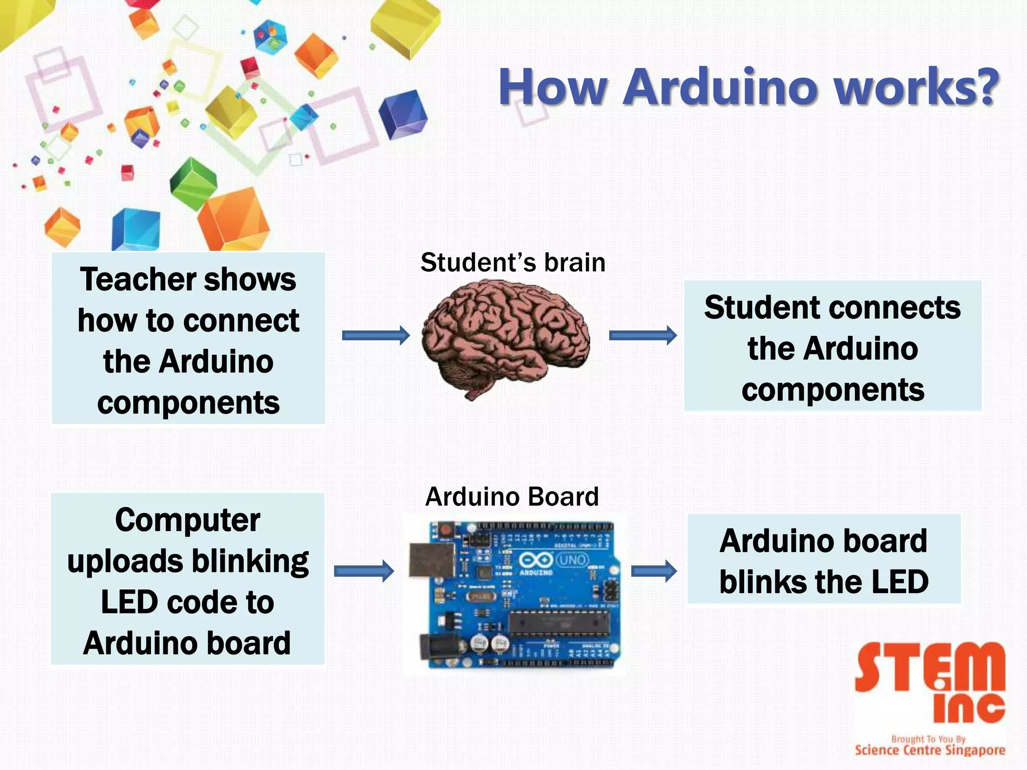


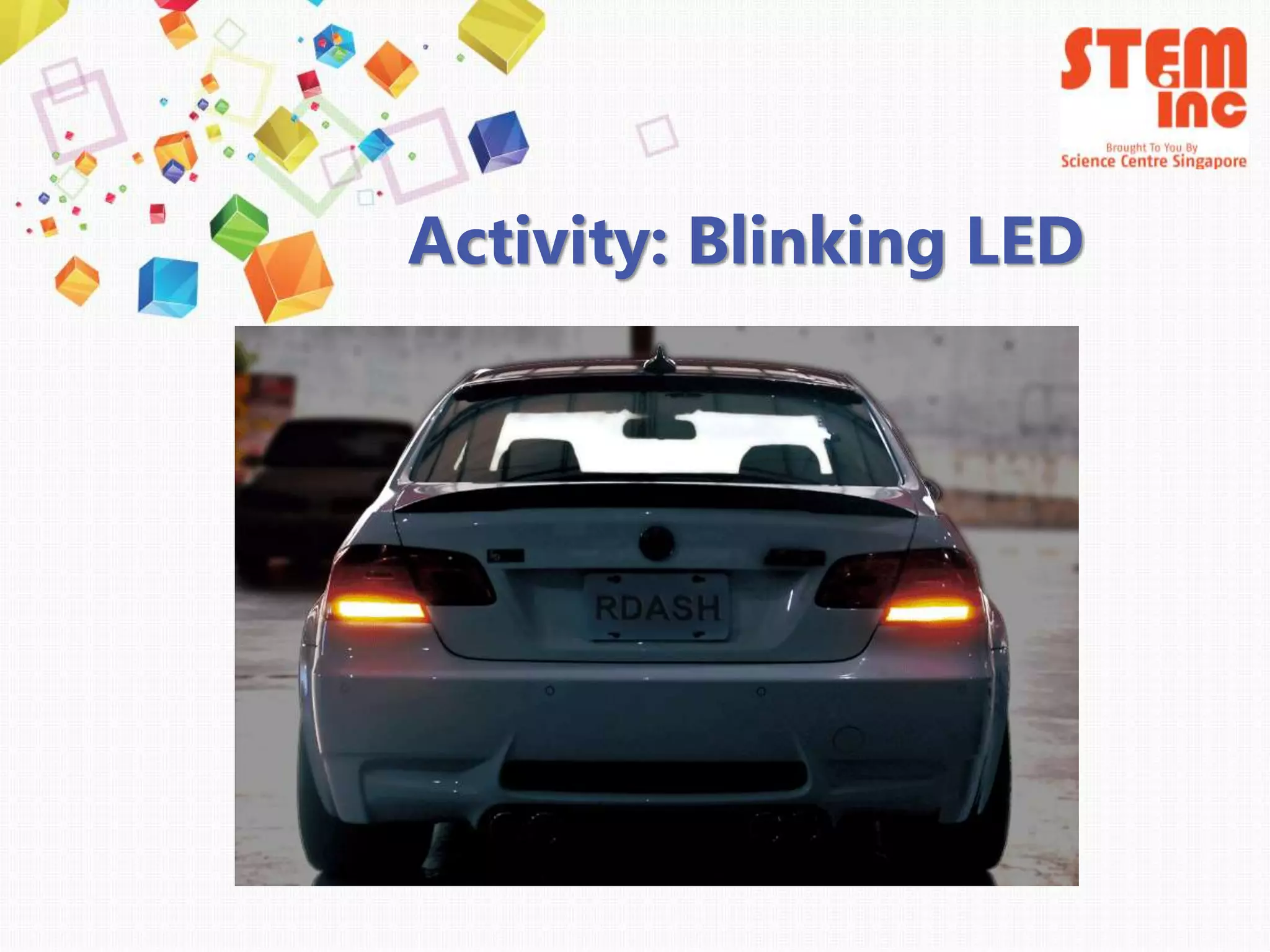
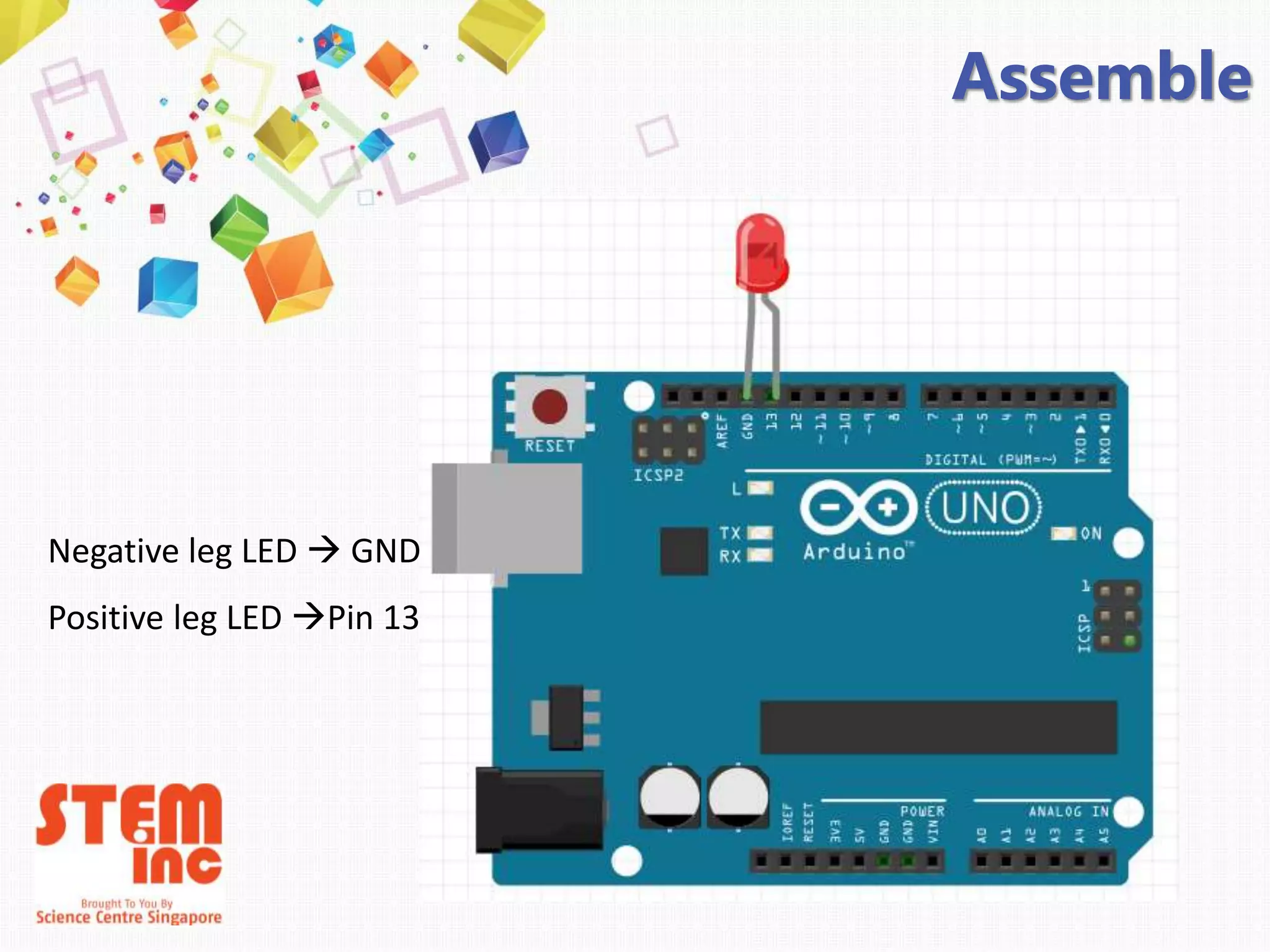
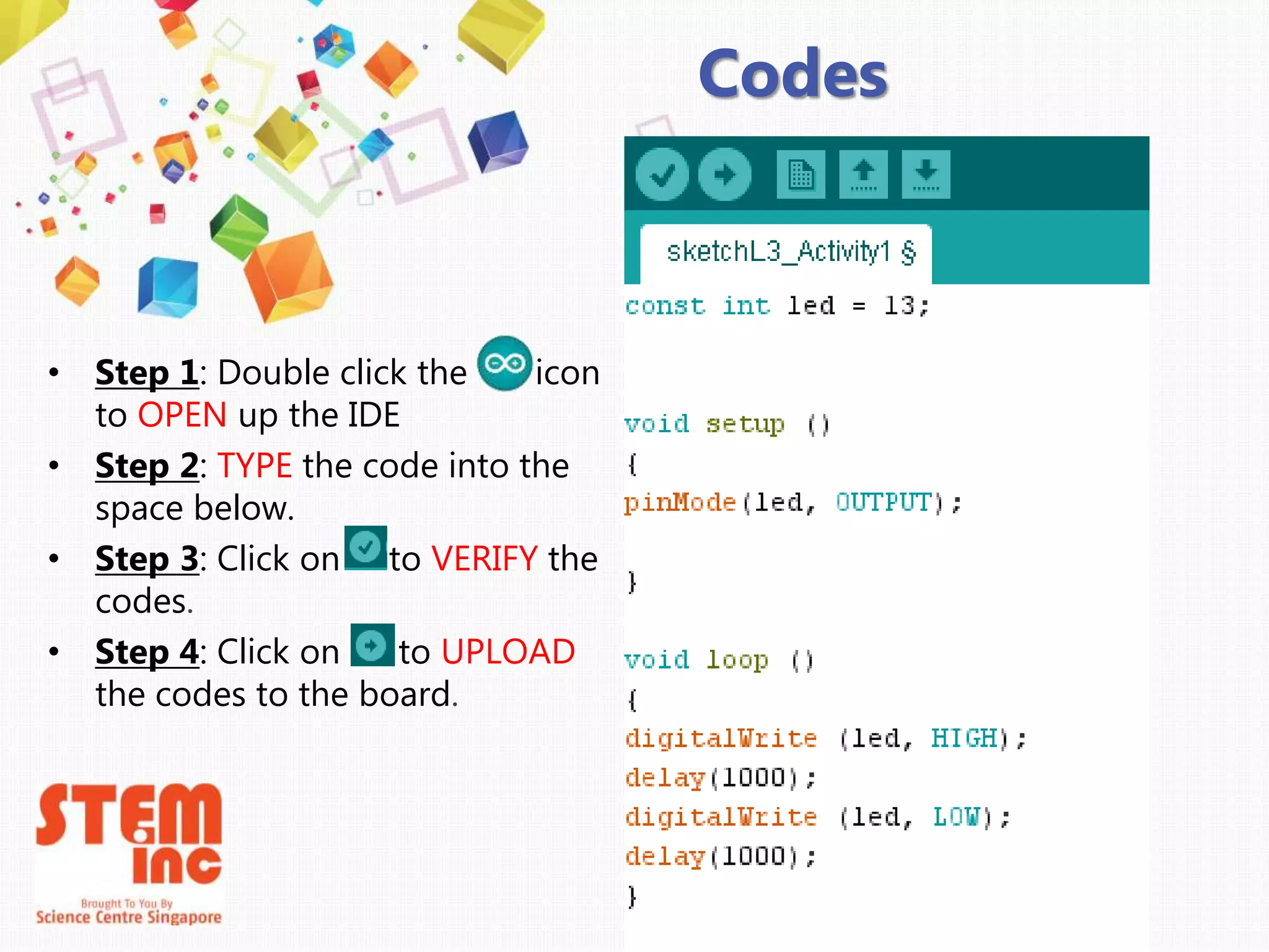
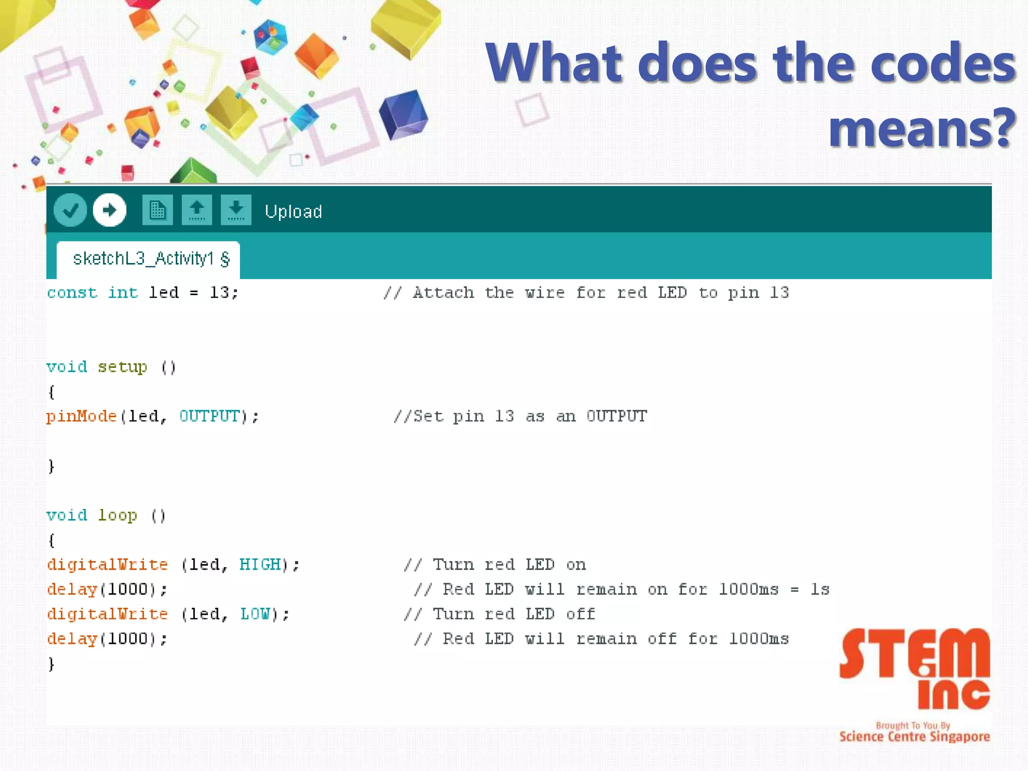
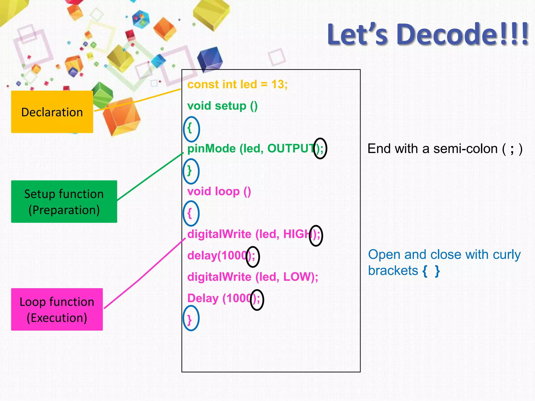
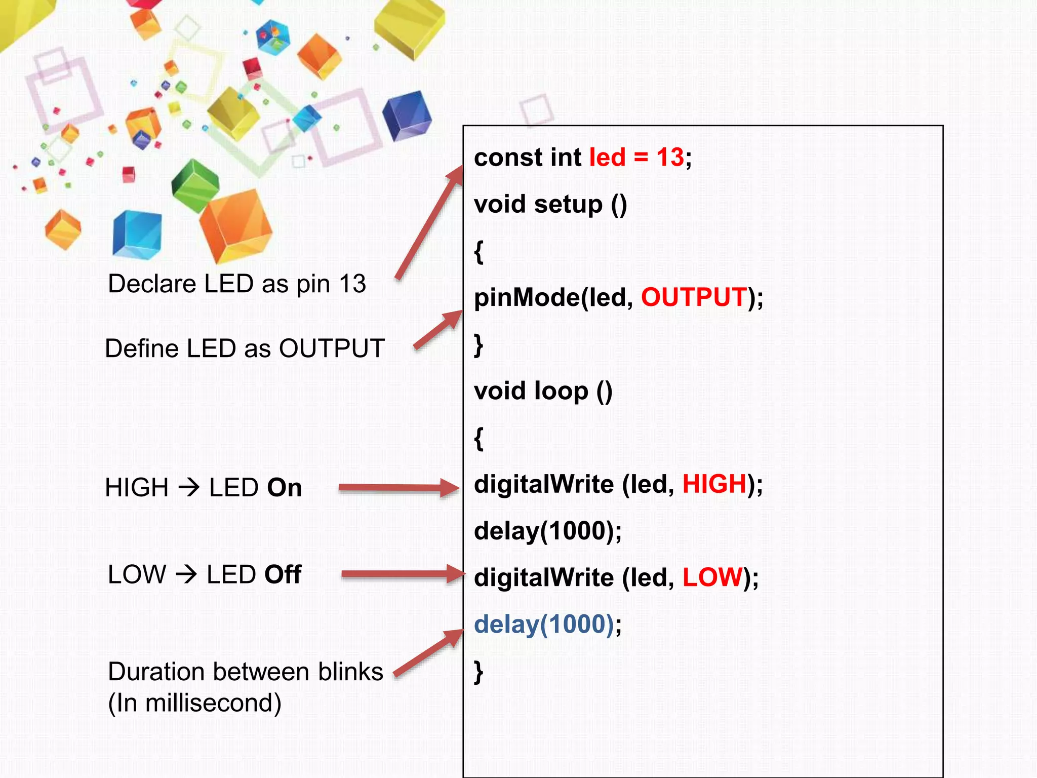

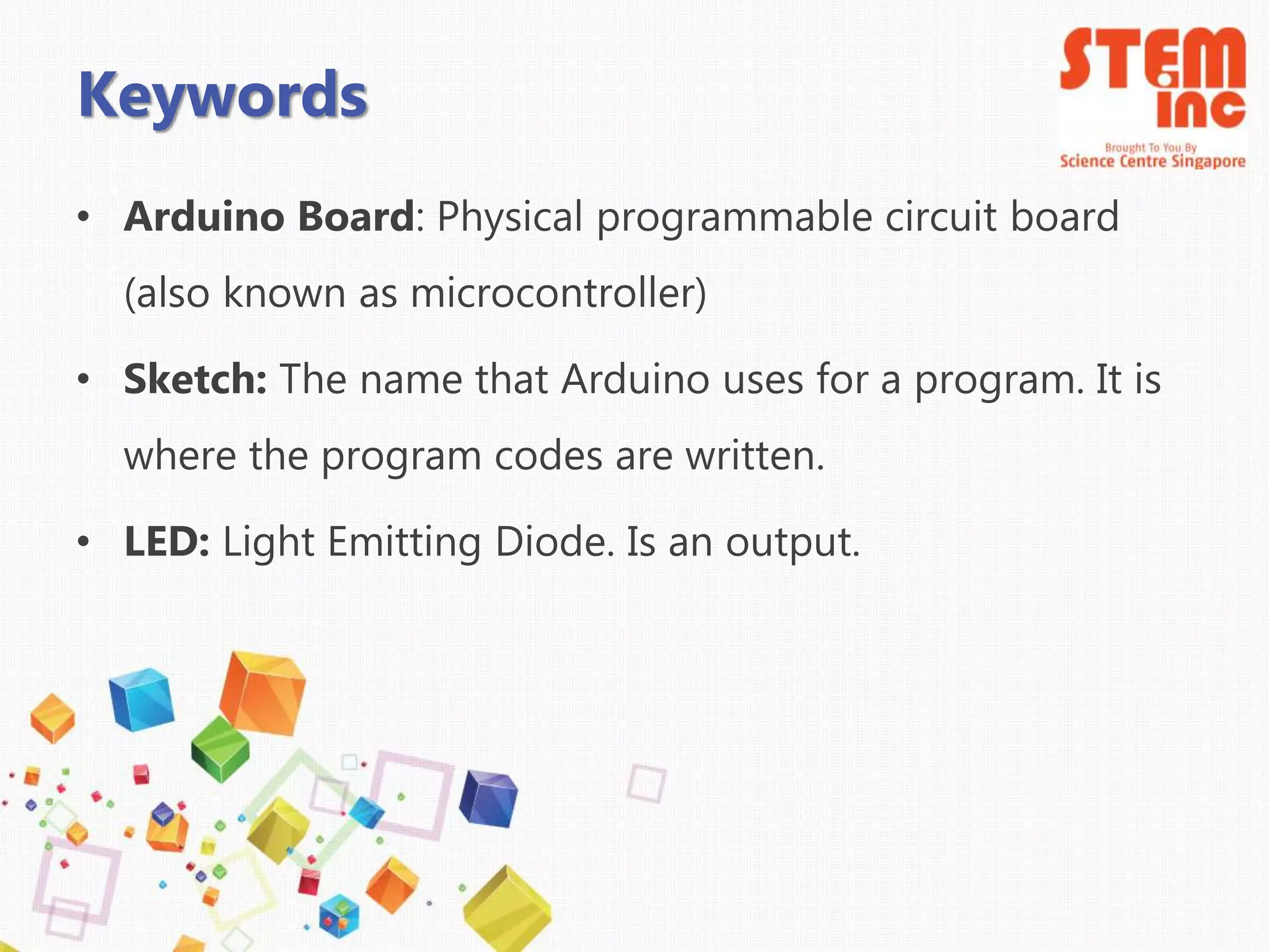

This document introduces Arduino by defining what it is, the parts of an Arduino board, and how to program it. An Arduino is a microcontroller board that can be used to develop interactive objects by taking various inputs (e.g. sensors) and controlling physical outputs (e.g. lights, motors). It explains the basic components of an Arduino board and how Arduino code is uploaded and run. A simple example is provided to blink an LED using Arduino code and by changing the delay times, the blinking speed can be adjusted. Keywords like Arduino board, sketch, and LED are also defined.


![Chapter 6 6_1_running_water_and_groundwater[1][1]](https://cdn.slidesharecdn.com/ss_thumbnails/chapter661runningwaterandgroundwater11-110706160352-phpapp01-thumbnail.jpg?width=640&height=640&fit=bounds)