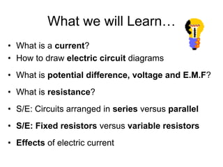
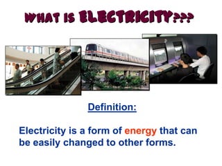
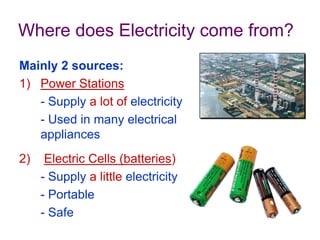
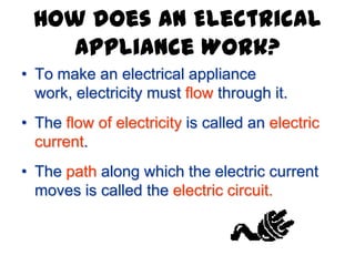
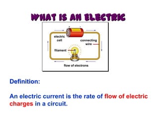
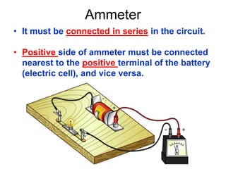
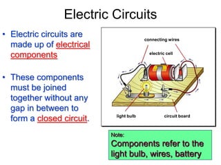
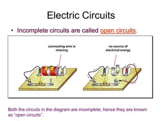
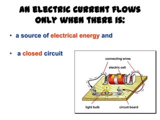
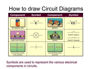
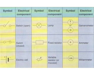
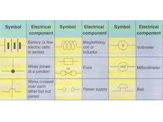
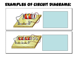
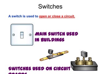
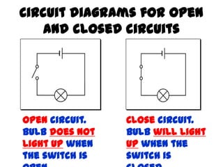
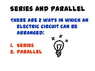
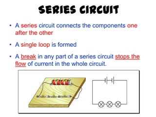
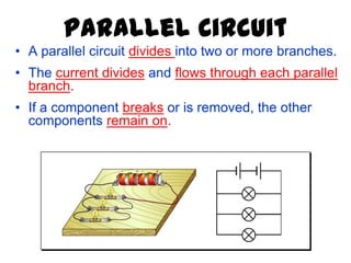
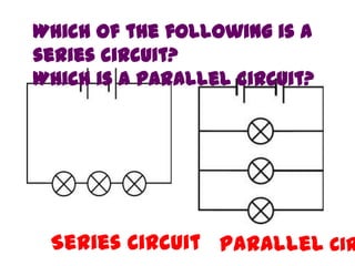
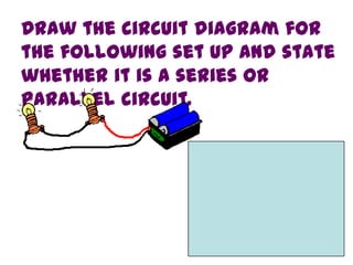
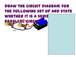
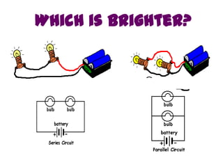
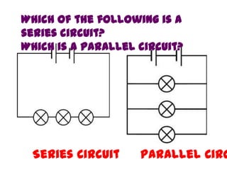
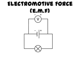
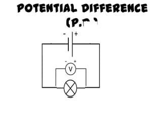
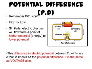
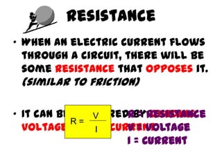
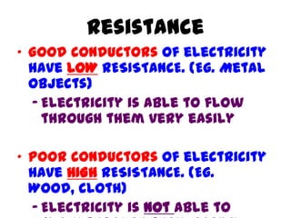
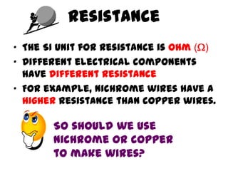
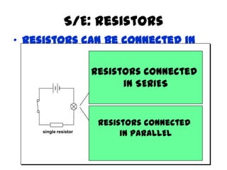
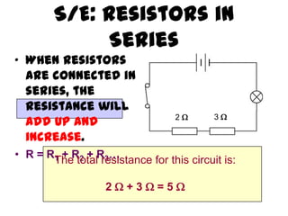
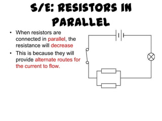
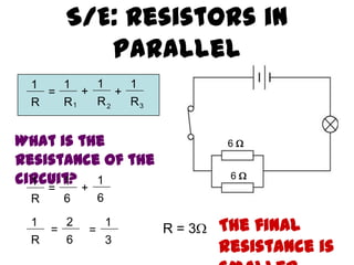
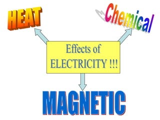
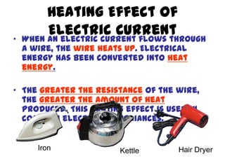
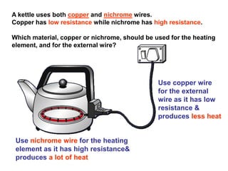
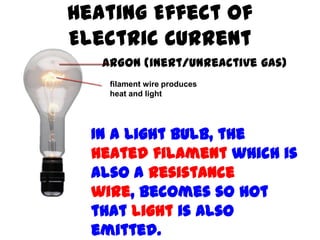
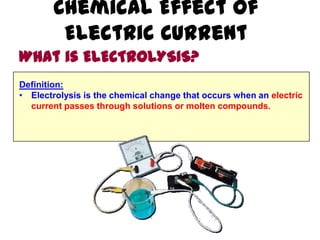
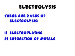
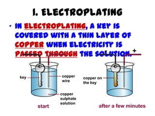
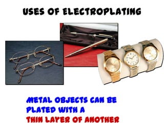
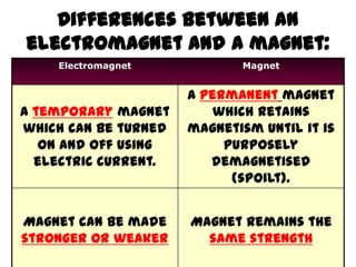
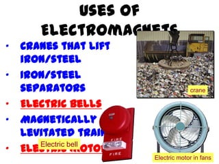
Electricity
Volume B Chapter 18
What we will Learn…
• What is a current?
• How to draw electric circuit diagrams
• What is potential difference, voltage and E.M.F?
• What is resistance?
• S/E: Circuits arranged in series versus parallel
• S/E: Fixed resistors versus variable resistors
• Effects of electric current
Definition:
Electricity is a form of energy that can
be easily changed to other forms.
What is Electricity???
Where does Electricity come from?
Mainly 2 sources:
1) Power Stations
- Supply a lot of electricity
- Used in many electrical
appliances
2) Electric Cells (batteries)
- Supply a little electricity
- Portable
- Safe
How does an Electrical
Appliance Work?
• To make an electrical appliance
work, electricity must flow through it.
• The flow of electricity is called an electric
current.
• The path along which the electric current
moves is called the electric circuit.
What is an Electric
Current???
Definition:
An electric current is the rate of flow of electric
charges in a circuit.
connecting
wire
electric
cell
filament
flow of electrons
Electric Charges
• Electric charges are made up of positive
charges (protons) and negative charges
(electrons).
• When these charges flow in a circuit, a
current is produced.
How does electricity flow?
• The battery in a circuit gives energy to
the electrons and pushes them around
a circuit, from the negative terminal of
the cell, round the circuit and back to
the positive terminal of the cell.
• The SI unit for electric current is ampere (A).
• Smaller currents are measured in
milliamperes (mA).
• Different electrical components and
appliances require different sizes of current
to turn them on.
How to Measure Current?
1 A = 1,000 mA
1 mA = 0.001 A
Instrument to Measure Current
• An ammeter is an instrument used for
measuring electric current.
Ammeter
• It must be connected in series in the circuit.
• Positive side of ammeter must be connected
nearest to the positive terminal of the battery
(electric cell), and vice versa.
Electric Circuits
• Electric circuits are
made up of electrical
components
• These components
must be joined
together without any
gap in between to
form a closed circuit.
connecting wires
electric cell
circuit boardlight bulb
Note:
Components refer to the
light bulb, wires, battery
Electric Circuits
• Incomplete circuits are called open circuits.
connecting wire is
missing
no source of
electrical energy
Both the circuits in the diagram are incomplete, hence they are known
as “open circuits”.
An electric current flows
only when there is:
• a source of electrical energy and
• a closed circuit
connecting wires
electric cell
circuit boardlight bulb
How to draw Circuit Diagrams
Component Symbol Component Symbol
An electric cell Battery
Light bulb (lamp) Switch
Switch (open)
Switch (closed)
Connecting wires
(not joined)
Connecting wires
(joined)
+ +
Symbols are used to represent the various electrical
components in circuits.
Examples of circuit diagrams:
Switches
A switch is used to open or close a circuit.
Main switch used
in buildings
Switches used on circuit
Circuit diagrams for open
and closed circuits
Open circuit.
Bulb does not
light up when
the switch is
Close circuit.
Bulb will light
up when the
switch is
Series and Parallel
There are 2 ways in which an
electric circuit can be
arranged:
1. Series
2. Parallel
Series Circuit
• A series circuit connects the components one
after the other
• A single loop is formed
• A break in any part of a series circuit stops the
flow of current in the whole circuit.
Parallel Circuit
• A parallel circuit divides into two or more branches.
• The current divides and flows through each parallel
branch.
• If a component breaks or is removed, the other
components remain on.
Which of the following is a
series circuit?
Which is a parallel circuit?
Series Circuit Parallel Cir
Draw the circuit diagram for
the following set up and state
whether it is a series or
parallel circuit.
Draw the circuit diagram for
the following set up and state
whether it is a series or
parallel circuit.
Which is brighter?
Which of the following is a
series circuit?
Which is a parallel circuit?
Series Circuit Parallel Circ
Voltage
• An electric cell gives energy to the electrons and
pushes them round a circuit. Voltage is a measure
of how much energy the electrons receive.
• Different voltages are supplied by different cells and
batteries.
12 V Car Battery
1.5 V Dry Cell
9 V Dry Cell
How to Measure
Voltage?
• The SI unit for voltage is volt
(V).
• A voltmeter is an instrument
used for measuring voltages.
Voltmeter
• Voltmeters must be connected
in parallel to the circuit.
• The positive side of voltmeter
is connected to the positive
terminal of the cell, and vice
versa.
Recall: Ammeter!!!
• It must be connected in series in the
circuit.
• Positive side of ammeter must be
connected nearest to the positive
terminal of the battery (electric
cell), and vice versa.
Electromotive Force
(e.m.f)
• Electromotive force is the
same as voltage.
• E.m.f refers to the amount of
energy supplied by the electric
source (eg. battery) to each unit
of electric charge.
Electromotive Force
(e.m.f)
Potential Difference
(P.d.)
Potential Difference
(p.d)• Remember Diffusion?
• High  Low
• Similarly, electric charges
will flow from a point of
higher potential (energy) to
lower potential
connecting
wire
electric
cell
filament
flow of electrons
•This difference in electric potential between 2 points in a
circuit is known as the potential difference. It is the same
as VOLTAGE also.
Resistance
• When an electric current flows
through a circuit, there will be
some resistance that opposes it.
(similar to friction)
• It can be measured by dividing
voltage by the current.
R =
V
I
R = Resistance
V = Voltage
I = Current
Resistance
• Good conductors of electricity
have LOW RESISTANCE. (Eg. Metal
objects)
– Electricity is able to flow
through them very easily
• Poor conductors of electricity
have HIGH RESISTANCE. (Eg.
Wood, cloth)
– Electricity is not able to
• The SI unit for resistance is ohm ()
• Different electrical components
have different resistance
• For example, nichrome wires have a
higher resistance than copper wires.
Resistance
So should we use
nichrome or copper
to make wires?
Example 1
• An electric rice cooker
operates at 240 V and uses a
current of 8 A. What is the
resistance of the rice cooker?Voltage (V)
= 240 V
Current (I)
= 8 A
R =
V
I
R =
240
8
= 30 
Resistors
• An electrical component that is specially made to have a
certain resistance is called a resistor.
• They can be connected in a circuit to resist the current
flow.
Fixed Resistors and
Variable Resistors
• Fixed resistors have only one resistance value
• Variable resistors can be adjusted to change
the resistance.
fixed resistor symbol variable resistor symbol
•Variable
resistors are
useful in light
dimmers and
S/E: Resistors
• Resistors can be connected in
series or parallel
single resistor
extra resistor in
series results in
dimmer bulb
extra resistor in
parallel results
in brighter bulb
Resistors connected
in SERIES
Resistors connected
in PARALLEL
S/E: Resistors in
Series
• When resistors
are connected in
series, the
resistance will
add up and
increase.
• R = R1 + R2 + R3…
2  3 
The total resistance for this circuit is:
2  + 3  = 5 
• When resistors are
connected in parallel, the
resistance will decrease
• This is because they will
provide alternate routes for
the current to flow.
S/E: Resistors in
Parallel
S/E: Resistors in
Parallel
6 
6 
1
R
=
1
R
1
R
1
R
+ +
1 2 3
What is the
resistance of the
circuit?1
R
=
1
6
1
6
+
1
R
=
2
6
1
3
= R = 3 The final
resistance is
What we will Learn…
• What is a current?
• How to draw electric circuit
diagrams
• What is potential difference, voltage
and E.M.F?
• What is resistance?
• S/E: Circuits arranged in series versus
parallel
Heating Effect of
Electric Current• When an electric current flows through
a wire, the wire heats up. Electrical
energy has been converted into heat
energy.
• The greater the resistance of the wire,
the greater the amount of heat
produced. This heating effect is used in
common electrical appliances.
Iron Kettle Hair Dryer
A kettle uses both copper and nichrome wires.
Copper has low resistance while nichrome has high resistance.
Which material, copper or nichrome, should be used for the heating
element, and for the external wire?
Use copper wire
for the external
wire as it has low
resistance &
produces less heat
Use nichrome wire for the heating
element as it has high resistance&
produces a lot of heat
filament wire produces
heat and light
In a light bulb, the
heated filament which is
also a resistance
wire, becomes so hot
that light is also
emitted.
Heating Effect of
Electric Current
ARGON (inert/unreactive gas)
Chemical Effect of
Electric Current
What is ELECTROLYSIS?
Definition:
• Electrolysis is the chemical change that occurs when an electric
current passes through solutions or molten compounds.
Electrolysis
There are 2 uses of
electrolysis:
1) Electroplating
2) Extraction of Metals
1. Electroplating
• In electroplating, a key is
covered with a thin layer of
copper when electricity is
passed through the solution.
key copper
wire
copper
sulphate
solution
start after a few minutes
copper on
the key
- +
Uses of Electroplating
Metal objects can be
plated with a
thin layer of another
2. Extraction of metals
• Some metals (eg. sodium, aluminium) are obtained
by electrolysis.
• To extract the metal
– heat the solid compound of the metal until it melts
– pass an electric current through the molten
compound
Magnetic Effect of a
Current• A straight wire is placed near a
compass. When an electric current
flows through the wire, the
compass needle is deflected. This
shows that an electric current has
a magnetic effect.
compass needle is
deflected
current
in wire
Electromagnet
• An electromagnet is a magnet that
is made by using electricity
• It consist of a wire coiled around a
metal rod (eg. Iron)coil of wire
to battery
iron core
compass needle is strongly
attracted to iron core
Electromagnet
The magnetic effect of the electromagnet can be
increased by:
1. increasing the current (by using more batteries)
2. increasing the number of turns of wire in the coil
3. Using an iron rod
Differences between an
electromagnet and a magnet:
Electromagnet Magnet
A temporary magnet
which can be turned
on and off using
electric current.
A permanent magnet
which retains
magnetism until it is
purposely
demagnetised
(spoilt).
Magnet can be made
stronger or weaker
Magnet remains the
same strength
Uses of
Electromagnets
• Cranes that lift
iron/steel
• Iron/steel
separators
• Electric bells
• Magnetically
levitated trains
• Electric motors
crane
Electric motor in fans
Electric bell
Made by:-
• POWERPOINT CENTRE
GANAUR

Electricity

  • 1.
  • 2.
    What we willLearn… • What is a current? • How to draw electric circuit diagrams • What is potential difference, voltage and E.M.F? • What is resistance? • S/E: Circuits arranged in series versus parallel • S/E: Fixed resistors versus variable resistors • Effects of electric current
  • 3.
    Definition: Electricity is aform of energy that can be easily changed to other forms. What is Electricity???
  • 4.
    Where does Electricitycome from? Mainly 2 sources: 1) Power Stations - Supply a lot of electricity - Used in many electrical appliances 2) Electric Cells (batteries) - Supply a little electricity - Portable - Safe
  • 6.
    How does anElectrical Appliance Work? • To make an electrical appliance work, electricity must flow through it. • The flow of electricity is called an electric current. • The path along which the electric current moves is called the electric circuit.
  • 7.
    What is anElectric Current??? Definition: An electric current is the rate of flow of electric charges in a circuit. connecting wire electric cell filament flow of electrons
  • 8.
    Electric Charges • Electriccharges are made up of positive charges (protons) and negative charges (electrons). • When these charges flow in a circuit, a current is produced.
  • 9.
    How does electricityflow? • The battery in a circuit gives energy to the electrons and pushes them around a circuit, from the negative terminal of the cell, round the circuit and back to the positive terminal of the cell.
  • 10.
    • The SIunit for electric current is ampere (A). • Smaller currents are measured in milliamperes (mA). • Different electrical components and appliances require different sizes of current to turn them on. How to Measure Current? 1 A = 1,000 mA 1 mA = 0.001 A
  • 11.
    Instrument to MeasureCurrent • An ammeter is an instrument used for measuring electric current.
  • 12.
    Ammeter • It mustbe connected in series in the circuit. • Positive side of ammeter must be connected nearest to the positive terminal of the battery (electric cell), and vice versa.
  • 14.
    Electric Circuits • Electriccircuits are made up of electrical components • These components must be joined together without any gap in between to form a closed circuit. connecting wires electric cell circuit boardlight bulb Note: Components refer to the light bulb, wires, battery
  • 15.
    Electric Circuits • Incompletecircuits are called open circuits. connecting wire is missing no source of electrical energy Both the circuits in the diagram are incomplete, hence they are known as “open circuits”.
  • 16.
    An electric currentflows only when there is: • a source of electrical energy and • a closed circuit connecting wires electric cell circuit boardlight bulb
  • 17.
    How to drawCircuit Diagrams Component Symbol Component Symbol An electric cell Battery Light bulb (lamp) Switch Switch (open) Switch (closed) Connecting wires (not joined) Connecting wires (joined) + + Symbols are used to represent the various electrical components in circuits.
  • 20.
  • 21.
    Switches A switch isused to open or close a circuit. Main switch used in buildings Switches used on circuit
  • 22.
    Circuit diagrams foropen and closed circuits Open circuit. Bulb does not light up when the switch is Close circuit. Bulb will light up when the switch is
  • 23.
    Series and Parallel Thereare 2 ways in which an electric circuit can be arranged: 1. Series 2. Parallel
  • 24.
    Series Circuit • Aseries circuit connects the components one after the other • A single loop is formed • A break in any part of a series circuit stops the flow of current in the whole circuit.
  • 25.
    Parallel Circuit • Aparallel circuit divides into two or more branches. • The current divides and flows through each parallel branch. • If a component breaks or is removed, the other components remain on.
  • 26.
    Which of thefollowing is a series circuit? Which is a parallel circuit? Series Circuit Parallel Cir
  • 27.
    Draw the circuitdiagram for the following set up and state whether it is a series or parallel circuit.
  • 28.
    Draw the circuitdiagram for the following set up and state whether it is a series or parallel circuit.
  • 29.
  • 30.
    Which of thefollowing is a series circuit? Which is a parallel circuit? Series Circuit Parallel Circ
  • 32.
    Voltage • An electriccell gives energy to the electrons and pushes them round a circuit. Voltage is a measure of how much energy the electrons receive. • Different voltages are supplied by different cells and batteries. 12 V Car Battery 1.5 V Dry Cell 9 V Dry Cell
  • 33.
    How to Measure Voltage? •The SI unit for voltage is volt (V). • A voltmeter is an instrument used for measuring voltages.
  • 34.
    Voltmeter • Voltmeters mustbe connected in parallel to the circuit. • The positive side of voltmeter is connected to the positive terminal of the cell, and vice versa.
  • 35.
    Recall: Ammeter!!! • Itmust be connected in series in the circuit. • Positive side of ammeter must be connected nearest to the positive terminal of the battery (electric cell), and vice versa.
  • 36.
    Electromotive Force (e.m.f) • Electromotiveforce is the same as voltage. • E.m.f refers to the amount of energy supplied by the electric source (eg. battery) to each unit of electric charge.
  • 37.
  • 38.
  • 39.
    Potential Difference (p.d)• RememberDiffusion? • High  Low • Similarly, electric charges will flow from a point of higher potential (energy) to lower potential connecting wire electric cell filament flow of electrons •This difference in electric potential between 2 points in a circuit is known as the potential difference. It is the same as VOLTAGE also.
  • 41.
    Resistance • When anelectric current flows through a circuit, there will be some resistance that opposes it. (similar to friction) • It can be measured by dividing voltage by the current. R = V I R = Resistance V = Voltage I = Current
  • 42.
    Resistance • Good conductorsof electricity have LOW RESISTANCE. (Eg. Metal objects) – Electricity is able to flow through them very easily • Poor conductors of electricity have HIGH RESISTANCE. (Eg. Wood, cloth) – Electricity is not able to
  • 43.
    • The SIunit for resistance is ohm () • Different electrical components have different resistance • For example, nichrome wires have a higher resistance than copper wires. Resistance So should we use nichrome or copper to make wires?
  • 44.
    Example 1 • Anelectric rice cooker operates at 240 V and uses a current of 8 A. What is the resistance of the rice cooker?Voltage (V) = 240 V Current (I) = 8 A R = V I R = 240 8 = 30 
  • 45.
    Resistors • An electricalcomponent that is specially made to have a certain resistance is called a resistor. • They can be connected in a circuit to resist the current flow.
  • 46.
    Fixed Resistors and VariableResistors • Fixed resistors have only one resistance value • Variable resistors can be adjusted to change the resistance. fixed resistor symbol variable resistor symbol •Variable resistors are useful in light dimmers and
  • 47.
    S/E: Resistors • Resistorscan be connected in series or parallel single resistor extra resistor in series results in dimmer bulb extra resistor in parallel results in brighter bulb Resistors connected in SERIES Resistors connected in PARALLEL
  • 48.
    S/E: Resistors in Series •When resistors are connected in series, the resistance will add up and increase. • R = R1 + R2 + R3… 2  3  The total resistance for this circuit is: 2  + 3  = 5 
  • 49.
    • When resistorsare connected in parallel, the resistance will decrease • This is because they will provide alternate routes for the current to flow. S/E: Resistors in Parallel
  • 50.
    S/E: Resistors in Parallel 6 6  1 R = 1 R 1 R 1 R + + 1 2 3 What is the resistance of the circuit?1 R = 1 6 1 6 + 1 R = 2 6 1 3 = R = 3 The final resistance is
  • 51.
    What we willLearn… • What is a current? • How to draw electric circuit diagrams • What is potential difference, voltage and E.M.F? • What is resistance? • S/E: Circuits arranged in series versus parallel
  • 53.
    Heating Effect of ElectricCurrent• When an electric current flows through a wire, the wire heats up. Electrical energy has been converted into heat energy. • The greater the resistance of the wire, the greater the amount of heat produced. This heating effect is used in common electrical appliances. Iron Kettle Hair Dryer
  • 54.
    A kettle usesboth copper and nichrome wires. Copper has low resistance while nichrome has high resistance. Which material, copper or nichrome, should be used for the heating element, and for the external wire? Use copper wire for the external wire as it has low resistance & produces less heat Use nichrome wire for the heating element as it has high resistance& produces a lot of heat
  • 55.
    filament wire produces heatand light In a light bulb, the heated filament which is also a resistance wire, becomes so hot that light is also emitted. Heating Effect of Electric Current ARGON (inert/unreactive gas)
  • 56.
    Chemical Effect of ElectricCurrent What is ELECTROLYSIS? Definition: • Electrolysis is the chemical change that occurs when an electric current passes through solutions or molten compounds.
  • 57.
    Electrolysis There are 2uses of electrolysis: 1) Electroplating 2) Extraction of Metals
  • 58.
    1. Electroplating • Inelectroplating, a key is covered with a thin layer of copper when electricity is passed through the solution. key copper wire copper sulphate solution start after a few minutes copper on the key - +
  • 59.
    Uses of Electroplating Metalobjects can be plated with a thin layer of another
  • 60.
    2. Extraction ofmetals • Some metals (eg. sodium, aluminium) are obtained by electrolysis. • To extract the metal – heat the solid compound of the metal until it melts – pass an electric current through the molten compound
  • 61.
    Magnetic Effect ofa Current• A straight wire is placed near a compass. When an electric current flows through the wire, the compass needle is deflected. This shows that an electric current has a magnetic effect. compass needle is deflected current in wire
  • 62.
    Electromagnet • An electromagnetis a magnet that is made by using electricity • It consist of a wire coiled around a metal rod (eg. Iron)coil of wire to battery iron core compass needle is strongly attracted to iron core
  • 63.
    Electromagnet The magnetic effectof the electromagnet can be increased by: 1. increasing the current (by using more batteries) 2. increasing the number of turns of wire in the coil 3. Using an iron rod
  • 64.
    Differences between an electromagnetand a magnet: Electromagnet Magnet A temporary magnet which can be turned on and off using electric current. A permanent magnet which retains magnetism until it is purposely demagnetised (spoilt). Magnet can be made stronger or weaker Magnet remains the same strength
  • 65.
    Uses of Electromagnets • Cranesthat lift iron/steel • Iron/steel separators • Electric bells • Magnetically levitated trains • Electric motors crane Electric motor in fans Electric bell
  • 66.