Downloaded 168 times

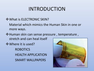
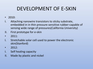
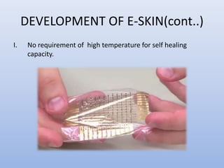
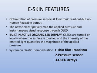
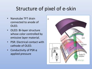
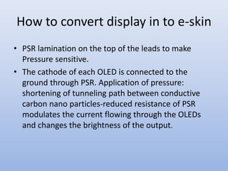


This document describes the development of an electronic skin (e-skin) that can instantly visualize applied pressure. Key points: - E-skin mimics human skin's ability to sense pressure, temperature, and stretch. The developed e-skin uses organic LED displays and pressure sensors on a flexible plastic substrate. - When pressure is applied, the conductivity of the pressure-sensitive rubber increases, modulating the current to the OLED and changing its brightness. This allows the e-skin to spatially map and display applied pressure. - The e-skin has potential applications in robotics, health monitoring devices, and smart surfaces. It represents an advance over previous e-skins by providing an integrated, human