This document summarizes a study on assessing the impact of faults on an induction motor drive operating under indirect field oriented control. The study develops a rotor flux DQ axis model of an induction motor and simulates various faults including voltage, current, speed, torque, and stator flux faults. Simulation results using MATLAB/Simulink show the impact of faults on motor performance indicators like voltage, current, speed, torque, and flux. Both open-loop and closed-loop indirect field oriented control schemes are evaluated. The analysis provides a method for assessing reliability of motor drives by observing their behavior under different fault conditions.
![International Journal of Computational Engineering Research||Vol, 03||Issue, 4||
www.ijceronline.com ||April||2013|| Page 1
Fault Impact Assessment on Indirect Field Oriented Control for
Induction Motor
1,
R.Senthil kumar, 2,
R.M.Sekar, 3,
L.Hubert Tony Raj, 4,
I.Gerald Christopher
Raj
1,
PG scholar, Department of EEE, PSNA College of Engineering & Technology Dindigul – 624 622, Tamilnadu,
India.
2,
Associate Professor, Department of EEE, PSNA College of Engineering & Technology Dindigul – 624 622,
Tamilnadu, India.
3,
PG scholar, Department of EEE, PSNA College of Engineering & Technology Dindigul – 624 622, Tamilnadu,
India.
4,
Associate Professor, Department of EEE, PSNA College of Engineering & Technology Dindigul – 624 622,
Tamilnadu, India.
I. INTRODUCTION
Reliability assessment of motor drives is essential, especially in electric transportation applications.
Safety is a major concern in such applications, and it is tied directly to re-liability. Induction machines, due to
their reliability and low cost, are widely used in industrial applications. However, several electro-mechanical
faults may occur during their life span. In industry, most failures interrupt a process and finally reduce or even
stop the production. Thus, expensive scheduled maintenance is performed in order to prevent sudden failure and
avoid economic damage[1].
The computer simulation for these various modes of operation is conveniently obtained from the
equations which describe the symmetrical induction machine in an arbitrary reference frame [2]. As in Fig. 1[3]
shows entire block diagram of induction motor drive. To control the rotor which creates torque equation is
called as rotor flux DQ model. while faults in supply voltage that is affected on stator voltage. that is not affected
on rotor voltage. Because rotor voltage produced due to electromagnetic induction principle. So rotor flux DQ
model is used. stator and synchronous reference frame is applicable for squirrel cage induction motor[2].
because rotor part in short circuited in squirrel cage induction motor.The rotor reference frame is applicable for
slip ring or
Fig. 1. Typical Induction Motor Drive
ABSTRACT:
This paper presents an induction motor drives operating under indirect field-oriented control
in which rotor flux DQ axis model is used. In this model, various faults are analyzed such as voltage,
current, speed and torque, stator flux. To develop the model, faults are first identified, and then, a
simulation model of the setup is developed. Faults are injected into the model in sequential levels and
the system performance is assessed after each fault. Here rotor flux DQ model of induction motor is
developed and it’s controlled by using indirect field oriented control is studied.Here IFOC with DQ
model was simulated using MATLAB/ SIMULINK software. Also the waveforms of voltage, current,
speed, torque, Q axis and D axis stator flux are obtained. The above faults are analyzed and rectified
which results in the increase of efficiency. This analysis is shown to be simple and useful for assessing
the reliability of motor drives.
Keywords : Fault impact assessment, Induction motor drive, Rotor flux DQ axis model,openloop and
closedloop IFOC](https://image.slidesharecdn.com/a034301010-130511023624-phpapp01/85/A034301010-1-320.jpg)
![International Journal of Computational Engineering Research||Vol, 03||Issue, 4||
www.ijceronline.com ||April||2013|| Page 1
Fault Impact Assessment on Indirect Field Oriented Control for
Induction Motor
1,
R.Senthil kumar, 2,
R.M.Sekar, 3,
L.Hubert Tony Raj, 4,
I.Gerald Christopher
Raj
1,
PG scholar, Department of EEE, PSNA College of Engineering & Technology Dindigul – 624 622, Tamilnadu,
India.
2,
Associate Professor, Department of EEE, PSNA College of Engineering & Technology Dindigul – 624 622,
Tamilnadu, India.
3,
PG scholar, Department of EEE, PSNA College of Engineering & Technology Dindigul – 624 622, Tamilnadu,
India.
4,
Associate Professor, Department of EEE, PSNA College of Engineering & Technology Dindigul – 624 622,
Tamilnadu, India.
I. INTRODUCTION
Reliability assessment of motor drives is essential, especially in electric transportation applications.
Safety is a major concern in such applications, and it is tied directly to re-liability. Induction machines, due to
their reliability and low cost, are widely used in industrial applications. However, several electro-mechanical
faults may occur during their life span. In industry, most failures interrupt a process and finally reduce or even
stop the production. Thus, expensive scheduled maintenance is performed in order to prevent sudden failure and
avoid economic damage[1].
The computer simulation for these various modes of operation is conveniently obtained from the
equations which describe the symmetrical induction machine in an arbitrary reference frame [2]. As in Fig. 1[3]
shows entire block diagram of induction motor drive. To control the rotor which creates torque equation is
called as rotor flux DQ model. while faults in supply voltage that is affected on stator voltage. that is not affected
on rotor voltage. Because rotor voltage produced due to electromagnetic induction principle. So rotor flux DQ
model is used. stator and synchronous reference frame is applicable for squirrel cage induction motor[2].
because rotor part in short circuited in squirrel cage induction motor.The rotor reference frame is applicable for
slip ring or
Fig. 1. Typical Induction Motor Drive
ABSTRACT:
This paper presents an induction motor drives operating under indirect field-oriented control
in which rotor flux DQ axis model is used. In this model, various faults are analyzed such as voltage,
current, speed and torque, stator flux. To develop the model, faults are first identified, and then, a
simulation model of the setup is developed. Faults are injected into the model in sequential levels and
the system performance is assessed after each fault. Here rotor flux DQ model of induction motor is
developed and it’s controlled by using indirect field oriented control is studied.Here IFOC with DQ
model was simulated using MATLAB/ SIMULINK software. Also the waveforms of voltage, current,
speed, torque, Q axis and D axis stator flux are obtained. The above faults are analyzed and rectified
which results in the increase of efficiency. This analysis is shown to be simple and useful for assessing
the reliability of motor drives.
Keywords : Fault impact assessment, Induction motor drive, Rotor flux DQ axis model,openloop and
closedloop IFOC](https://image.slidesharecdn.com/a034301010-130511023624-phpapp01/75/A034301010-1-2048.jpg)
![Fault Impact Assessment On Indirect…
www.ijceronline.com ||April||2013|| Page 2
wound rotor induction motor. Here synchronous reference frame is presented. because while converting
3 phase to 2 phase which all parts considering DC quantity and control method is simple. The d-axis component
is aligned with the rotor flux vector and regarded as the flux-producing current component. On the other hand, the
q-axis current, which is perpendicular to the d-axis, is solely responsible for torque production.Based on the
pioneering work of Blaschke, high performance induction motor drives have been developed in recent decades.
The high dynamic performance is achieved using the field-orientation theory which requires controlling the stator
current vector relative to the rotor flux [4].The indirect field oriented control method is essentially the same as
direct oriented control, except the unit vector signals are generated in feed forward manner [5]. Indirect field
oriented control is very popular in industries IFOC being more commonly used because in closed-loop mode such
drives more easily operate throughout the speed range from zero speed to high-speed field-weakening in DFOC,
flux magnitude and angle feedback signals are directly calculated using so-called voltage or current models.In this
paper, a complete framework for induction motor under indirect field oriented control (IFOC) is presented. Here
cover the faults in voltage, current, speed, torque, Q and D axis stator flux. In this paper change the
voltage and to study can be carried out to motor performance.
II. DYNAMIC MODEL OF INDUCTION MOTOR
The dynamic model model of squirrel cage induction motor[SEIM] in stationary reference frame in α-
β reference frame variables [6].
Fig. 2. Equivalent Circuit of SCIM (a) α axis (b) β axis
Components stator and rotor voltage of the induction motor can be expressed as follows:
(1)
(2)
(3)
(4)
The components of rotor flux linkage in the stationary reference can be written as
+ (5)
+ (6)
Where and are the residual rotor flux linkages in α-β axis, respectively.
Then, with an electrical rotor speed of ,the components of rotating voltage in the stationary reference
frame are as the follows:
(7)
(8)
The expressions for capacitor voltages are,
(9)](https://image.slidesharecdn.com/a034301010-130511023624-phpapp01/85/A034301010-2-320.jpg)
![Fault Impact Assessment On Indirect…
www.ijceronline.com ||April||2013|| Page 3
(10)
Using Fig. 2 equations (1)-(10), for the matrix equations of SCIM at no-load in the stationary reference frame
are given by
=
(11)
From (11), can be written the state equations as follows:
(12)
Where,
A = , B =
,
I. INDUCTION MOTOR MODEL IN DQ0 SYNCHRONOUS REFERENCE FRAMES
Fig. 3. Change of variables 3Φ to 2Φ conversion
Using Fig. 3[7] Synchronous frame induction motor equations are given as eqn 13 to eqn 17.
Stator voltage equations:
(13)
Rotor voltage equations:
(14)
Where,](https://image.slidesharecdn.com/a034301010-130511023624-phpapp01/85/A034301010-3-320.jpg)
![Fault Impact Assessment On Indirect…
www.ijceronline.com ||April||2013|| Page 4
= (15)
Torque Equations:
Nm (16)
III. INDIRECT FIELD ORIENTED CONTROL OF INDUCTION MOTOR
Fig. 4 shows the block diagram of indirect field orientation control strategy with sensor in which speed
regulation is possible using a control loop.
Fig. 4. Indirect Field-Oriented Control for Induction Motor Drives
In IFOC, flux space angle feed forward and flux magnitude signals first measure stator currents and rotor speed
for then deriving flux space angle proper by summing the rotor angle corresponding to the rotor speed and the
calculated reference value of slip angle corresponding to the slip frequency. An induction motor drive under
IFOC requires measurements of the three-phase currents and speeds and has two control inputs for torque, or
speed, androtor flux[8].
p = 0 steady state (17)
= (18)
(19)
(20)
The reference currents of the q-d-o axis ( , ) are converted to the reference phase vlotages ( , ) as
the commanded voltages for the control loop.By using ,which is shown in equation(17) and using actual
rotor speed, the rotor flux position is obtained.
(21)
or
(22)
As shown in Fig. 4., two-phase current feeds the Clarke transformation block. These projection outputs
are indicated as and . These two components of the current provide the inputs to Park’s transformation,
which gives the currents in the excitation reference frame. The and components, which are outputs
of the Park transformation block, are compared to their reference values , the flux reference, and , the
torque reference. The torque command, , comes from the output of the speed controller. The flux command,
, is the output of the flux controller which indicates the right rotor flux command for every speed reference.
Magnetizing current is usually between 40 and 60% of the nominal current. For operating in speeds above
the nominal speed, a field weakening section should be used in the flux controller section. The current regulator
outputs, and are applied to the inverse Park transformation.The outputs of this block are the signals that
drive the inverter.](https://image.slidesharecdn.com/a034301010-130511023624-phpapp01/85/A034301010-4-320.jpg)
![Fault Impact Assessment On Indirect…
www.ijceronline.com ||April||2013|| Page 5
IV. MOTOR DRIVE, FAULTS AND PERFORMANCE
A. System Overview
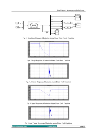
As in Fig. 4 faults can occur in the following six possible subsystems or components:
[1] Faults due to voltage variations
[2] Faults due to current variations
[3] Faults due to speed variations
[4] Faults due to load torque variations
[5] Faults due to Q axis Stator Flux Variations
[6] Faults due to D axis Stator Flux Variations
B. Voltage Variation
In this paper to change the voltage and to study can be carried out to motor performance. To control the
induction motor by using indirect field oriented control method. Many problems are a result of high or low
voltage, unbalanced voltage, ungrounded power systems, or voltage spikes[9].
V. SIMULATION AND EXPERIMENTS
Some of the faults could damage the experimental setup and cannot be tested directly. Also, many
commercial motor drives have built-in protection circuitry and algorithms that take action after a fault by shutting
down or otherwise altering operation. It is not easy (or advisable) to override protection, but fault modes used here
can also integrate protection in several aspects.. Even though the simulations here do not model or cover all
physical dynamics, noise, vibration, power loss, and nonlinearities of material, they provide a useful tool that
can save the cost of rebuilding a motor drive, or most other systems, after severe failures.
A. Simulations
Simulations provide a safe environment to evaluate even the most extreme faults, provided a simulation
has been validated in hardware. Some commercial drives have fault detection and isolation, which would not be
helpful if the target is to observe drive performance under faults, Simulations of the IFOC induction motor
drive shown in Fig. 4 were performed in MATLAB/SIMULINK for a 1.5-hp induction machine. The inverter
involved IGBT–diode pairs from the SimPowerSystems Toolbox in SIMULINK.For the implementation of the
state space equations of a system model, MATLAB/ SIMULINK. has the denominated user defined functions or
s-functions [10]. In these blocks the code that defines the model in state equations can be written. In this code so
much is defined the number of inputs and outputs, like the states and the state space equations of the system.
This s-function will correspond to a block with the inputs, outputs and parameters shown in Fig. 5. The s-
function can be called from a MATLAB/SIMULINK s-function block. In Fig. 5,one is the SIMULINK block
diagram where “VSI-IM model” is the s-function that call’s the defined function. The inputs are multiplexed in
a bus can be demultiplexed, and the same occurs for the outputs.Here rotor flux DQ model of induction motor
is presented in programmed manner by using M-File.and fault analysis also written in the same M-File. While
changing the voltage it will affect current, speed, torque and flux.
TABLE I. MACHINE PARAMETERS
Sl.no Machine Parameters in perunit
1 Stator resistance Rs = 0.01
2 Rotor resistance Rr = 0.02
3 Stator leakage inductance Lsl =0.1
4 Rotor leakage inductance Lrl =0.1
5 Magnetizing inductance Lm = 4.5
6 Load torque Tl = 0.2375
7 Supply voltage Vs =1.0](https://image.slidesharecdn.com/a034301010-130511023624-phpapp01/85/A034301010-5-320.jpg)
![Fault Impact Assessment On Indirect…
www.ijceronline.com ||April||2013|| Page 9
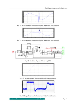
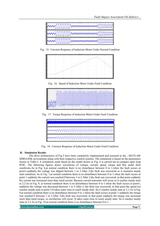
when the fault occurs at point 1 suddenly the Q axis stator flux was reached 0 between 1 to 2.After
2,the fault was recovered, in that point suddenly the flux was increased more than rated flux. so oscillations will
occur. It takes some time to reach normal state. So it reaches steady state at 2.2. As in Fig. 11, at normal
condition there is no disturbance between 0 to 1.when the fault occurs at point 1 suddenly the D axis stator flux
was reached 0 between 1 to 2.After 2,the fault was recovered, in that point suddenly the flux was increased more
than rated flux. so oscillations will occur. It takes some time to reach normal state. So it reaches steady state at
2.2.
C. Experimental Environment
The experimental setup includes all control, power electronics, motor, load, and measurements. The
control and some measurements are available on an eZdspF2812 platform which is based on a Texas
Instruments TMS320F2812 DSP. This control platform is integrated into the Grainger Center Modular Inverter
[11] which also includes an inverter power stage rated at 400V and 100A. A dynamometer is used to set the load
torque. Measurements include speed, torque, currents, voltages, and input and output power. All control and
measurement devices, including the dynamometer, are controlled using MATLAB/ Simulink through the
Simulink Real-Time Workshop. Communication between the software and the DSP occurs through real-time
data exchange (RTDX) via a parallel port. Here fault monitoring kit is also needed to analyze various faults.
There are two factors are considered. The first factor is to avoid injecting faults that could cause severe failures
or trigger the protection circuitry as predicted from simulations. The second factor is to use a tight external
closed-loop torque control in experiments to avoid sudden overload conditions on the dynamometer and the
motor shaft. The experimental setup is shown in Fig. 13,
Fig. 19. Experimental setup for model validation.
VI. CONCLUSION
The Existing methodology for reliability modeling covers essential faults in a drive system, including
the machine, power electronics converters, and sensors. The methodology leads to rotor flux DQ model of an
induction motor drive under open loop IFOC and can be extended to other drives or to more faults in other
components. A model was validated in experiments and used for the complete procedure. The survivor function
of the complete system was found analytically including fault coverage. Simplifications were proposed based on
dominant fault modes, which were found to be faults in the voltage, current, speed, load torque and stator flux.
Further research could apply this methodology to other drive topologies, more components in any topology
(e.g., link capacitors, gate drives, etc.), design of fault tolerance, and actual field failure rates. Even though DQ’s
model might not be accurate since faults generally vary with time, the proposed methodology serves the purpose
of a comprehensive, straightforward, and versatile reliability modeling procedure. Thus the open loop and
closed loop IFOC with DQ model is simulated using MATLAB/ SIMULINK.
REFERENCES
[1] Ali. M. Bazzi, Alejandro Dominguez-Garcia, and Philip T. Krein,“Markov Reliability Modeling for Induction Motor Drives
Under Field-Oriented Control,” IEEE Trans. Power Electron., Vol, No. 2, feb 2012.
[2] P. C Krause and C. H Thomas, ”Simulation of Symmetrical Induction Machinery” IEEE Trans., Power Apparatus and Systems
Vol. PAS-84, No. 11,1965
[3] A. M. Bazzi, A. D. Dominguez-Garcia, and P. T. Krein “A method for impact assessment of faults on the performance of
field oriented control drives: A first step to reliabilty modeling” in Proc. IEEE Appl. power Electron. Conf. Expo., 2010,
pp. 256–263
[4] Zsolt Beres and Peter Vranka, ”Sensor less IFOC of Induction Motor With Current Regulators in Current Reference Frame”
IEEE Trans. Ind. Appl., Vol. 37, No.4.2001.
[5] Alfio consoli, Giuseppe Scarcella and Antonio Testa,”Slip Frequency Detection for Indirect Field Oriented Control Drives”
IEEE Trans. Ind. Appl., Vol, No.1.,2004.](https://image.slidesharecdn.com/a034301010-130511023624-phpapp01/85/A034301010-9-320.jpg)
![Fault Impact Assessment On Indirect…
www.ijceronline.com ||April||2013|| Page 10
[6] G . R .Slemon, “ Modeling of Induction Machines for Electric Drives” IEEE Trans. Ind. Appl., Vol. 25, No.6, pp. 1126-1131,
Nov/Dec 1989.
[7] S. Green, D. J. Atkinson, A. G. Jack, B. C. Mecrow, and A. king, “ Sensor less operation of a Operation of a Fault Tolerant
PM Drive,” IEE Proc. Elect. Power Appl., Vol. 150, No.2,pp.117-125,Mar.2003
[8] Naceri Farid, Belkacem Sebti, Kercha Memberka and Benmokrane Tayed, “Performance Analysis of Field- Oriented Control
and Direct Torque Control for Sensorless Induction Motor Drives” in Proc. 15th
Mediterranean Conf., on Contol & Automation,
July 2007.
[9] W. R. Finley, M. M. Hodowanec, W.G. Holter, “ An Analytical Approach to Solving Motor Vibration Problems” IEEE PCIC
Conf., Sep 1999.
[10] Bin Wu, S. B. Dewan and G. R. Slemon,” PWM CSI Inverter Induction Motor Drives” IEEE Trans. Ind. Appl., Vol.28, No.1.
pp 64-71, 1992
[11] J. Kimball, M. Amerhein, A. Kwansinki, J. Mossoba, B. Nee, Z. Sorchini, W. Weaver, J. Weels and G. Zhang, “Modular
Inverter for Advanced Control Applications” Technical Report CEME-TR-200-01, University of Illinois May 2006.](https://image.slidesharecdn.com/a034301010-130511023624-phpapp01/85/A034301010-10-320.jpg)