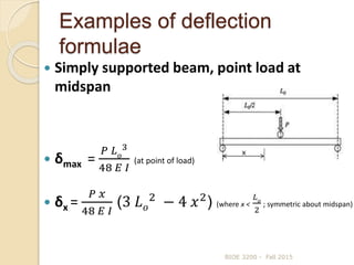
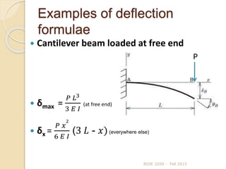
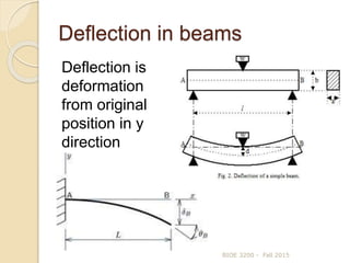
This document discusses beam deflection. It begins by defining beam deflection and the factors that affect it, including bending moment, material properties, and shape properties. It then presents the general formula for calculating beam deflection using double integration of the bending moment equation. Examples are given of using boundary conditions to solve for deflection in simply supported beams, cantilever beams, and beams under various loading types. Common deflection formulas are also presented.
![How to calculate beam deflection
using double integration method
BIOE 3200 - Fall 2015
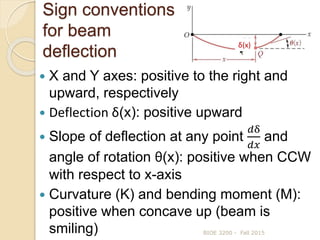
δ(x)
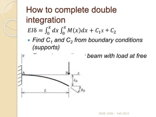
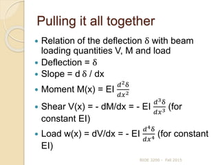
EI = Flexural Rigidity
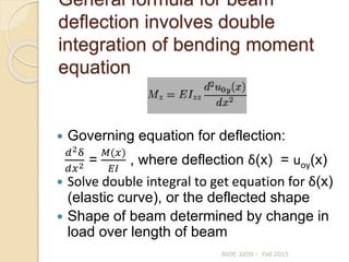
Governing equation:
𝑑2δ
𝑑𝑥2 =
𝑀
𝐸𝐼
𝐸𝐼
𝑑δ
𝑑𝑥
= 0
𝑥
𝑀 𝑥 𝑑𝑥 + 𝐶1 Note:
𝑑δ
𝑑𝑥
= tan θ ≈ θ(x)
𝐸𝐼θ(x) = 0
𝑥
𝑀 𝑥 𝑑𝑥 + 𝐶1
𝐸𝐼δ = 0
𝑥
[ 0
𝑥
𝑀 𝑥 𝑑𝑥 + 𝐶1 ] dx + 𝐶2
𝐸𝐼δ = 0
𝑥
𝑑𝑥 0
𝑥
𝑀 𝑥 𝑑𝑥 + 𝐶1x + 𝐶2 - general formula for
beam deflection](https://image.slidesharecdn.com/8beamdeflection-151017152844-lva1-app6892/85/8-beam-deflection-7-320.jpg)