24 THEORY OF SIMPLE BENDING, ASSUMPTIONS, DERIVATION
OF BENDING EQUATION,
BY
Dr. D.GOVARDHAN
PROFESSOR & HEAD
DEPARTMENT OF AERONAUTICAL ENGINEERING
INSTITUTE OF AERONAUTICAL ENGINEERING
(Autonomous)
DUNDIGAL, HYDERABAD - 500 043
1
MECHANICS OF SOLIDS
Don’t write or
place any image in
this area
2
Course Title MECHANICS OF SOLODS
Course Code AAEB04
Class B.TECH III SEM
Section A & B
Name of the Faculty Dr. D.GOVARDHAN
Lecture hour - Date 07-09-2020
Course Outcome/s Explain the bending stresses and their distribution along the
sections in simple and composite beams for evaluating its
bending strength
Topic Covered Bending Stresses In simple beams
Topic Learning Outcome Discuss the bending stresses at various loading conditions
in simple beams.
MECHANICS OF SOLIDS
3
The bending moments and shearing
forces are set up at all sections of a
beam, when it is loaded with some
external loads.
The bending moment at a section
tends to bend or deflect the beam and
the internal stresses resist its bending,
till the process of bending stops.
The resistance, offered by the internal
stresses, to the bending, is called
bending stress, and the relevant
theory is called the theory of simple
bending.
BENDING STRESSES IN SIMPLE BEAMS
Don’t write or
place any image in
this area
4
The following assumptions are made in the theory of simple bending:
1. The material of the beam is perfectly homogeneous i.e., of the same
kind throughout) and isotropic (i.e., of equal elastic properties in all
directions).
2. The beam material is stressed within its elastic limit and thus, obeys
Hooke’s law.
3. The transverse sections, which were plane before bending, remains
plane after bending also.
4 Each layer of the beam is free to expand or contract, independently, of
the layer above or below it
5 The value of E (Young’s modulus of elasticity) is the same in tension
and compression.
6 The beam is in equilibrium i.e., there is no resultant pull or push in the
beam section.
BENDING STRESSES IN SIMPLE BEAMS
Don’t write or
place any image in
this area
5
Consider a small length of a simply supported beam subjected
to a bending moment as shown in Figure 1 (a).
Now consider two sections AB and CD, which are normal to
the axis of the beam RS.
Due to action of the bending moment, the beam as a whole
will bend as shown in Fig. 1 (b).
Considering a small length of dx of the beam, therefore the
curvature of the beam in this length, is taken to be circular.
A little consideration will show that the top layer of the beam
has suffered compression and reduced to A′C′.
As proceeding towards the lower layers of the beam, the layers
RS, which has suffered no change in its length, though bent
into R′S′.
THEORY OF SIMPLE BENDING
Don’t write or
place any image in
this area
6
On further proceeding towards the lower layers,
the layers have suffered tension, as a result of
which the layers are stretched.
The amount of extension increases as proceeding
lower and the lowermost layer BD which has been
stretched to B′D′ having maximum tension.
It is concluded that layers above have been
compressed and those below RS have been
stretched.
This layer RS, which is neither compressed nor
stretched, is known as neutral plane or neutral
layer.
This theory of bending is called theory of simple
bending.
THEORY OF SIMPLE BENDING
Don’t write or
place any image in
this area
7
Figure1. Simple bending
Consider a small length dx of a beam subjected to a
bending moment as shown in figure 2(a).
As a result of this moment, let this small length of
beam bend into an arc of a circle with O as centre
as shown in figure 2 (b).
Let M = Moment acting at the beam,
θ = Angle subtended at the centre by the arc
R = Radius of curvature of the beam
Now consider a layer PQ at a distance y from RS
the neutral axis of the beam.
Let this layer be compressed to P′ Q′ after bending
as shown in figure 2 (b).
The decrease in length of this layer δl = PQ – P′ Q′
BENDING STRESS
Don’t write or
place any image in
this area
8
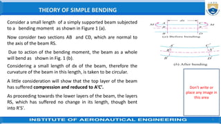
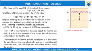
∴ Strain ε = δl/ Original length = [P Q - P′ Q′]/ PQ
Now from the geometry of the curved beam, the
two sections OP′ Q′ and OR′ S′ are similar.
∴ P′ Q′ / R′ S′ = (R− y) / R
or 1 - P′ Q′ / R′ S′ = 1 - (R− y) / R
ε = (R′ S′ - P′ Q′) / R′ S′
= [R- (R−y)]/R =y/R
∴ PQ = R′ S = Neutral axis
It is thus obvious, that the strain (ε) of a layer is
proportional to its distance from the neutral axis.
The bending stress σb = Strain × Elasticity
= ε × E = (y / R) E
= (R/E)y
BENDING STRESS Cont….,
Don’t write or
place any image in
this area
9
∵ Since E and R are constants, therefore
the stress at any point is directly
proportional to y,
i.e., the distance of the point from the
neutral axis.
The above expression may also be written
as, σ b / y = E/ R
NOTE. Since the bending stress is inversely
proportional to the radius (R), therefore
for maximum stress the radius should be
minimum and vice versa
BENDING STRESS
Don’t write or
place any image in
this area
10
Problem 1: A copper wire of 2 mm diameter is required to
be wound around a drum. Find the minimum radius of the
drum, if the stress in the wire is not to exceed 80 MPa. Take
modulus of elasticity for the copper as 100 Gpa.
Problem 1:
BENDING STRESS Cont….,
Don’t write or
place any image in
this area
Solution. Given : Diameter of wire (d) = 2 mm ;
Maximum bending stress σb (max) = 80 Mpa
= 80 N/mm2 and
Modulus of elasticity (E) = 100 Gpa = 100 × 103N/mm2.
The distance between the neutral axis of the wire and its
extreme fibre y = 2/2 = 1 mm
∴ Minimum radius of the drum R = (E / σb (max) ) × y
= 100 × 103 x 1/ 80
= 1.25 × 103 mm = 1.25 m
11
∴ Minimum radius of the drum (R)
= [y/ σ(max)] x E
= [1/ 80] x 100 × 103 N/mm2
= 1.25 × 103 mm = 1.25 m Ans.
BENDING STRESS Cont….,
Don’t write or
place any image in
this area
Problem 2: A steel wire of 5 mm diameter is bent into a
circular shape of 5 m radius. Determine the maximum
stress induced in the wire. Take E = 200 GPa.
SOLUTION. Given : Diameter of steel wire (d) = 5 mm ;
Radius of circular shape (R) = 5 m = 5 × 103 mm and
Modulus of elasticity (E) = 200 GPa
= 200 × 103 N/mm2 .
The distance between the neutral axis of the wire and
its extreme fibre, y = d/2 = 5 /2 = 2.5 mm and
Maximum bending stress induced in the wire
σb (max) = (E / R) × y = 200 × 103 × 2.5 / 5 × 103
= 100 N/mm2 = 100 MPa Ans.
12
∴ Minimum radius of the drum (R)
= [y/ σ(max)] x E
= [1/ 80] x 100 × 103 N/mm2
= 1.25 × 103 mm = 1.25 m Ans.
BENDING STRESS Cont….,
Don’t write or
place any image in
this area
Problem 3: A metallic rod of 10 mm diameter is bent into a
circular form of radius 6 m. If the maximum bending stress
developed in the rod is 125 MPa, find the value of Young’s
modulus for the rod material.
SOLUTION. Given : Diameter of rod (d) = 10 mm ;
Radius (R) = 6 m = 6 × 103 mm and
Maximum bending stress σb(max) = 125 MPa = 125 N/mm2 .
The distance between the neutral axis of the rod and its
extreme fibre, y = 10 /2 = 5
Young’s modulus for the rod material, E = (σb (max) / y) × R
= (125/ 5) × 6 × 103
∵ E = 150 × 103 N/mm2 = 150 GPa Ans.
25 NEUTRAL AXIS, MOMENT OF RESISTANCE, BENDING STRESSES
IN RECTANGULAR AND CIRCULAR SECTIONS (SOLID AND
HOLLOW)
BY
Dr. D.GOVARDHAN
PROFESSOR & HEAD
DEPARTMENT OF AERONAUTICAL ENGINEERING
INSTITUTE OF AERONAUTICAL ENGINEERING
(Autonomous)
DUNDIGAL, HYDERABAD - 500 043
13
MECHANICS OF SOLIDS
Don’t write or
place any image in
this area
14
Consider a small length of a simply supported beam subjected
to a bending moment as shown in Figure 1 (a).
Now consider two sections AB and CD, which are normal to
the axis of the beam RS.
Due to action of the bending moment, the beam as a whole
will bend as shown in Fig. 1 (b).
Considering a small length of dx of the beam, therefore the
curvature of the beam in this length, is taken to be circular.
A little consideration will show that the top layer of the beam
has suffered compression and reduced to A′C′.
As proceeding towards the lower layers of the beam, the layers
RS, which has suffered no change in its length, though bent
into R′S′.
THEORY OF SIMPLE BENDING
Don’t write or
place any image in
this area
15
On further proceeding towards the lower layers,
the layers have suffered tension, as a result of
which the layers are stretched.
The amount of extension increases as proceeding
lower and the lowermost layer BD which has been
stretched to B′D′ having maximum tension.
It is concluded that layers above have been
compressed and those below RS have been
stretched.
This layer RS, which is neither compressed nor
stretched, is known as neutral plane or neutral
layer.
This theory of bending is called theory of simple
bending.
THEORY OF SIMPLE BENDING
Don’t write or
place any image in
this area
16
The line of intersection of the neutral layer, with
any normal cross-section of a beam, is known as
neutral axis of that section.
The one side of the neutral axis there are
compressive stresses, whereas on the other there
are tensile stresses.
At the neutral axis, there is no stress of any kind.
Consider a section of the beam as shown in figure 3. Let
be the neutral axis of the section.
Consider a small layer PQ of the beam section at a
distance from the neutral axis .
Let δA = Area of the layer PQ.
The intensity of stress in the layer PQ
(σ) = y x E/ R
Figure 3: Neutral axis
POSITION OF NEUTRAL AXIS
Don’t write or
place any image in
this area
17
∴ The force on the layer PQ = Intensity of stress × Area
= y x (E/R) × δA and
Total force of the beam section = ∫ y x (E/R) × δA
= ∫ ( E / R) × y × δA = ( E / R) ∫ y × δA
Figure 3: Neutral axis
For pure bending, there is no force on the section of the
beam or the section is in equilibrium, therefore total
force , from top to bottom, must be equal to zero.
∴ (E/R) ∫ y. δA = 0 or ∫ y . δA = 0 (∵E/R are constants)
POSITION OF NEUTRAL AXIS
The y × δA is the moment of the area about the neutral axis
and Σ y × δ a is the moment of the entire area of the cross-
section about the neutral axis.
The moment of the entire area of any section is is zero about
the axis. Hence the neutral axis of a section is coincides with
centroidal axis,. This centroidal axis will be the neutral axis of
the section.
18
It is observed that on one side of the neutral axis there are
compressive stresses and on the other there are tensile stresses.
Due to these stresses, the forces will be acting on the layers. These
forces form a moment about N.A.
The total moment of these forces about the N A for a section is
known as Moment of a resistance of that section..
Consider a section of the beam as shown in figure. 6.
Let NA be the neutral axis of the section Figure 6: moment of resistance
MOMENT OF RESISTANCE
Don’t write or
place any image in
this area
19
Now consider a small layer PQ of the beam section at a
distance y from the neutral axis
Let δA = Area of the layer PQ.
Then force in the layer PQ (σ)= y. E/ R
∴ Total stress in the layer PQ= (E /R) x δA
The moment of this total forces about the neutral axis =
(E /R) x Y. δA. Y
= (E/R) y2.δA
The algebraic sum of all such moments about the
neutral axis must be equal to M. Therefore M = ∫(E/R)
y2.δA
Figure 6: moment of resistance
MOMENT OF RESISTANCE
Don’t write or
place any image in
this area
20
The expression ∫ y2.δA represents the moment of inertia of the
area of the whole section about the neutral axis.
Therefore M = (E/R) × I
(where I = moment of inertia) or
M/I = E/R. but σ/y = E/R
∴ M/I= σ/y = E/R
This equation is known as bending equation
It is the most important equation in the theory of simple
bending, which gives us relation between various
characteristics of a beam.
MOMENT OF RESISTANCE
Don’t write or
place any image in
this area
21
It is observed that there is no stress at the neutral
axis. In a simply supported beam, there is a
compressive stress above the neutral axis and a
tensile stress below it.
It is also noted that the stress at a point is directly
proportional to its distance from the neutral axis.
Hence the stresses in a simply supported beam
section, varied across the section can be
represented as shown in figure 5.
The maximum stress (either compressive or
tensile) takes place at the outermost layer.
Fig 5: Distribution of bending stress
DISTRIBUTION OF BENDING STRESS ACROSS THE SECTION
Don’t write or
place any image in
this area
22
Or in other words, while obtaining maximum bending stress at
a section, the value of y is taken as maximum.
Fig 5: Distribution of bending stress
The relation for finding out the bending stress on the extreme
fibre of a section, i.e.,
M/I= σ/y or M = I x σ/y
From this relation, the stress in a fibre is proportional to its
distance from the cg. If y max is the distance between the CG of
the section and the extreme fibre of the stress,
then M = σ max × I / y max
= σ max × Z where Z = I x ymax
The term ‘Z’ is known as modulus of section or section modulus.
DISTRIBUTION OF BENDING STRESS ACROSS THE SECTION
Don’t write or
place any image in
this area
23
The general practice of writing the above equation is M = σ × Z, where σ denotes the
maximum stress, tensile or compressive in nature.
if the section of a beam to, is symmetrical, its centre of gravity and hence the neutral
axis will lie at the middle of its depth.
The modulus of section of the following sections:
1. Rectangular section. 2. Circular section
1. Rectangular section (IG)= bd3/12,
∴ Modulus of section (Z)= bd2/6 (∵ y = d/2)
2. Circular section: (IG) =(π/64)d4,
∴ Modulus of section
Z = ((π/64)d4 /(d/2) = (π/32)d3
Note : If the given section is hollow, then the
corresponding values for external and internal
dimensions should be taken
MODULUS OF SECTION
Don’t write or
place any image in
this area
24
Note : If the given section is hollow, then the corresponding values for
external and internal dimensions should be taken
It is also termed as flexural strength of a section, which means the moment
of resistance offered by it. The relations M = I x σ/y = σ x z
It is thus obvious that the moment of resistance depends upon moment of
inertia (or section modulus) of the section.
In the case of a beam, subjected to transverse loading, the bending stress at
a point is directly proportional to its distance from the neutral axis.
Don’t write or
place any image in
this area
MODULUS OF SECTION
25
Prob 1: Two beams are simply supported over the same span and have the same flexural strength.
Compare the weights of these two beams, if one of them is solid and the other is hollow circular with
internal diameter half of the external diameter.
Solution. Given : Span of the solid beam = Span of the hollow beam and
Flexural strength of solid beam = Flexural strength of the hollow section.
Let D = Diameter of the solid beam and D1 = Diameter of the hollow beam.
Figure 6 a & b: Solid beam
STRENGTH OF A SECTION
Don’t write or
place any image in
this area
26
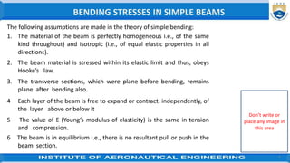
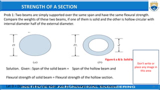
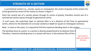
Since both the beams are supported over the same span (l) and have the same flexural strength,
therefore section modulus of both the beams must be equal.
Now equating equations (i) and (ii),
(1/32) π×D3 = (1/32) π× 0.9375D1
3-
or D3 = 0.9375 (D1
)3 ∴ D3 = (0.9375)D1
3 ∴D = 0.98 D1
The weights of two beams are proportional to their respective cross-sectional areas.
The section modulus of the solid section(Z1)= (1/32) π×D3 ---------------(i)
Now consider the hollow beam as shown in figure 6(b).
The section modulus of the hollow section(Z2) = (1/32) π×(D4
1 – d4)/D1
Since D1 = 2xd ∴Z2 = (1/32) π×[(D4
1 – (0.5D1)4]/D1 = (1/32) π× 0.9375D1
3--(ii)
STRENGTH OF A SECTION
Don’t write or
place any image in
this area
27
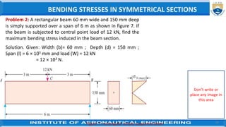
∴ Weight of solid beam /Weight of hollow beam =
Area of solid beam/Area of hollow beam
(1/4) π×D2 / (1/4) π× ( D1
2 –d2) = (1/4) π×D2 /(1/4) π× ( D1
2 –0. D1
2)
= (1/4) π×D2 /(1/4) π× [( D1
2 –(0.5 D1
2)] =1.28
since D = 0.98 D1
The section modulus of the solid section(Z1)= (1/32) π×D3 ---------------(i)
Now consider the hollow beam as shown in figure 6(b).
The section modulus of the hollow section(Z2) = (1/32) π×(D4
1 – d4)/D1
Since D1 = 2xd ∴Z2 = (1/32) π×[(D4
1 – (0.5D1)4]/D1 = (1/32) π× 0.9375D1
3--(ii)
STRENGTH OF A SECTION
Don’t write or
place any image in
this area
28
In a symmetrical section (i.e., circular, square or rectangular), the centre of gravity of the section lies
at the geometrical centre of the section as shown in figure 7.
Since the neutral axis of a section passes through its centre of gravity, therefore neutral axis of a
symmetrical section passes through its geometrical centre.
In such cases, the outermost layer or extreme fibre is at a distance of d/2 from its geometrical
centre, where d is the diameter (in a circular section) or depth (in square or rectangular sections).
Note : In most or the cases, it is required to find the maximum bending stress in the section.
The bending stress at a point, in a section is directly proportional to its distance from the neutral axis.
Therefore, maximum bending stress in a section will occur in the extreme fibre of the section.
STRENGTH OF A SECTION
Don’t write or
place any image in
this area
29
Problem 2: A rectangular beam 60 mm wide and 150 mm deep
is simply supported over a span of 6 m as shown in figure 7. If
the beam is subjected to central point load of 12 kN, find the
maximum bending stress induced in the beam section.
Solution. Given: Width (b)= 60 mm ; Depth (d) = 150 mm ;
Span (l) = 6 × 103 mm and load (W) = 12 kN
= 12 × 103 N.
Figure 7: rectangular simply supported beam
BENDING STRESSES IN SYMMETRICAL SECTIONS
Don’t write or
place any image in
this area
30
The maximum bending moment at the centre of a simply supported
beam subjected to a central point load,
M = Wl /4 = (12 x103) (6 x10³) /4 = 18 × 106 N-mm
Section modulus of the rectangular section (Z) = 60 x (150)2 / 6
= 25 × 103 mm3
∴ Maximum bending stress (σmax) =M/Z= 18×106 / 225×103
= 80 N/mm2 = 80 MPa
Problem 3: A cantilever beam is rectangular shown in figure 8, in section
having 80 mm width and 120mm depth. If the cantilever is subjected to a
point load of 6 kN at the free end and the bending stress is not to exceed 40
MPa, find the span of the cantilever beam.
Solution. Given data: Width (b) = 80 mm; Depth(d) = 120 mm ;
Point load (W) = 6 kN = 6×10³ N and Max. bending stress = 40Mpa= 40
N/mm2
STRENGTH OF A SECTION
Don’t write or
place any image in
this area
31
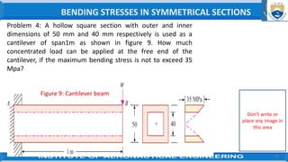
Maximum bending stress (σmax) = 40 MPa = 40 N/mm2 , Let l = Span of the cantilever beam.
The section modulus (Z) = bd2/6 = 80 x 1202/6 = 192 × 103 mm3
The maximum bending moment at the fixed end of the cantilever subjected to a point load at the free
end(M) = Wl = (6 × 10³) × l
∴ Maximum bending stress [σb (max)] = 40 = M/Z = (6×10³)×l / 192×103
l = 40 x 192×103 / (6×10³) = 40 × 32 = 1280 mm = 1.28 m Ans.
Figure 8: A cantilever beam
BENDING STRESSES IN SYMMETRICAL SECTIONS
Don’t write or
place any image in
this area
32
Problem 4: A hollow square section with outer and inner
dimensions of 50 mm and 40 mm respectively is used as a
cantilever of span1m as shown in figure 9. How much
concentrated load can be applied at the free end of the
cantilever, if the maximum bending stress is not to exceed 35
Mpa?
Figure 9: Cantilever beam
BENDING STRESSES IN SYMMETRICAL SECTIONS
Don’t write or
place any image in
this area
33
Let W = Concentrated load that be applied at the free end of the
cantilever.
The moment of inertia of the hollow square section,
I=BD3/12−bd3/12
=50x503/12−40 x403/12 = 307.5 × 103 mm4
∴ Modulus of section, Z = I/ (B/2) = 307.5 103/50
= 12300 mm3 and
Solution. Given :
Outer width (or depth) (B) = 50 mm ;
Inner width (or depth) = (b) = 40 mm;
Span (l) = 1 × 103 mm and
maximum bending stress
σb (max) = 35 MPa = 35 N/mm2
BENDING STRESSES IN SYMMETRICAL SECTIONS
Don’t write or
place any image in
this area
34
Maximum bending moment at the fixed end of the cantilever
subjected to a point load at the free end,M = Wl = W × (1 × 10³) =
1×10³ W
∴ Maximum bending stress (σmax) = 35 = M/Z
= 1×10³ W / 12300
and hence W = 430.5 N Ans.
Problem 5. A hollow steel tube having external and internal
diameter of 100 mm and 75 mm respectively is simply
supported over a span of 5 m as shown in figure 10. The tube
carries a concentrated load of W at a distance of 2 m from one
of the supports. What is the value of W, if the maximum
bending stress is not to exceed 100 Mpa.
BENDING STRESSES IN SYMMETRICAL SECTIONS
Don’t write or
place any image in
this area
35
Given : External diameter (D) = 100 mm, Internal diameter
(d) = 75 mm ;
Span (l) = 5 m = 5 × 103 mm ;
Distance AC (a) = 2m = 2 × 103 mm or
Distance BC (b) = 5-2 = 3m = 3×103 mm
Maximum bending stress (σmax) = 100 MPa = 100 N/mm2.
Figure 10. simply supported
BENDING STRESSES IN SYMMETRICAL SECTIONS
Don’t write or
place any image in
this area
36
The maximum bending moment over a simply supported beam
subjected to an eccentric load (M) = W x a x b / l = W x 2×103 x
3×103 /5×103
= 1.2 x10³ W Nm
The section modulus of a hollow circular section(Z) = π(D4- d4) /
(64 x D/2)
= π(1004- 754) / (64 x 100/2)
= 67.1 × 103 mm3
The maximum bending stress [σb max] = M/Z
or 100 = 1.2 x10³ W / 67.1 × 10³
∴ W = 5.6 × 10³ N = 5.6 kN Ans.
BENDING STRESSES IN SYMMETRICAL SECTIONS
Don’t write or
place any image in
this area
37
There are many types of composite beams that we come across, but
the following are the important.
1. Beams of unsymmetrical sections,
2. Beams of uniform strength and
3. Flitched beams.
1. BEAMS OF UNSYMMETRICAL SECTIONS
In a symmetrical section, it is observed that the
distance of extreme fibre from the CG . of the
section y = d/2.
But this is not the case, in an unsymmetrical
section (L, I, T, etc.), since the neutral axis of such
section does not pass through the geometrical
centre of The section..
BENDING STRESSES IN COMPOSTE SECTIONS
Don’t write or
place any image in
this area
38
In such cases, first the centre of gravity of the
section is to be determined and then determine the
values of y, in the tension and compression sides.
For obtaining the bending stress in a beam, the
bigger value of y (in tension or compression) is
used in the equation.
Problem 6: Two wooden planks 150 mm × 50 mm each are
connected to form a T-section of a beam as shown in figure 11.
If a moment of 6.4 kN-m is applied around the horizontal
neutral axis, inducing tension below the neutral axis, find the
bending stresses at both the extreme fires of the cross- section.
BENDING STRESSES IN COMPOSTE SECTIONS
Don’t write or
place any image in
this area
26 BENDING STRESSES IN I AND T SECTIONS,
BY
Dr. D.GOVARDHAN
PROFESSOR & HEAD
DEPARTMENT OF AERONAUTICAL ENGINEERING
INSTITUTE OF AERONAUTICAL ENGINEERING
(Autonomous)
DUNDIGAL, HYDERABAD - 500 043
39
MECHANICS OF SOLIDS
Don’t write or
place any image in
this area
40
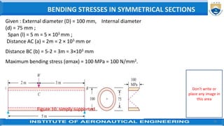
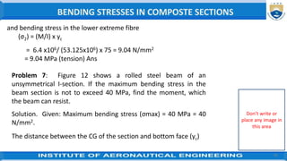
Figure 11 : T-section of a beam
Two planks forming the T-section are shown in figure 1
First find the centre of gravity of the beam section.
The distance between the centre of gravity of the section and its
bottom face (yc)
= [(150 x50) 175+ (150 x 50) 75] / [(150 x 50) + (150 x 50)] =
1875000/15000 =125 mm
Solution. Given: Size of wooden planks = 150
mm × 50 mm and
moment (M) = 6.4 kN-m
= 6.4 × 10⁶ N-mm.
BENDING STRESSES IN COMPOSTE SECTIONS
Don’t write or
place any image in
this area
41
∴ Distance between the centre of gravity of the section and the
upper extreme fibre (yt)
= 200 – 125 = 75 mm
Distance between the centre of gravity of the section and the lower
extreme fibre yc = 125 mm
Moment of inertia of the T section about an axis passing through its
c.g. and parallel to the bottom face (I) =150 x (50)3 /12 + (150 x
50) (175 - 125)2
+ 50 x (150)3 /12 + (150 x 50) (125 - 75)2
= (20.3125 × 10⁶) + (32.8125 × 10⁶) mm4
= 53.125 × 106 mm4
∴ Bending stress in the upper extreme fibre (σ1) = (M/I) x yt = (6.4
x106 / 53.125x10⁶/) × 125
= 15.06 N/mm2 = 15.06 Mpa (Comp)
BENDING STRESSES IN COMPOSTE SECTIONS
Don’t write or
place any image in
this area
42
and bending stress in the lower extreme fibre
(σ2) = (M/I) x yc
= 6.4 x10⁶/ (53.125x106) x 75 = 9.04 N/mm2
= 9.04 MPa (tension) Ans
Problem 7: Figure 12 shows a rolled steel beam of an
unsymmetrical I-section. If the maximum bending stress in the
beam section is not to exceed 40 MPa, find the moment, which
the beam can resist.
Solution. Given: Maximum bending stress (σmax) = 40 MPa = 40
N/mm2.
The distance between the CG of the section and bottom face (yc)
BENDING STRESSES IN COMPOSTE SECTIONS
Don’t write or
place any image in
this area
yc = [(100 x50)275+(200x 50)150+(200x 50)25]/
[(100 x50) +(200 x 50)+(200 50)] = 125 mm
∴ y1 = 300 – 125 = 175 mm and y2 = 125 mm
Thus take the value of y = 175 mm
(i.e. greater of the two values between y1 and y2).
The moment of inertia of the I-section about an axis
passing through its centre of gravity and parallel to the bottom
face,
Figure 12
BENDING STRESSES IN COMPOSTE SECTIONS
Don’t write or
place any image in
this area
I = [100 x (50) 3 /12 + (100 x 50) (275 -125)2 ]+
[50 x(200)3 /12 + (50 x 200) x (150 –
125)2] + [200 x(50)3 /12 + (200 x50)
(125- 50)2]
= 255.2×106 mm4
Section modulus of the I-section(Z) = I/y
= 255.2 106/175
= 1.46 × 106 mm3
∴ Moment, which the beam can resist (M)
= σmax × Z
= 40 × (1.46 × 106)
= 58.4 × 10⁶ N-mm = 58.4 kN-m Ans.
BENDING STRESSES IN COMPOSTE SECTIONS
Don’t write or
place any image in
this area
45
Don’t write or
place any image in
this area
27 BENDING STRESSES IN ANGLE AND CHANNEL SECTIONS,
DESIGN OF SIMPLE BEAM SECTIONS, BEAMS OF UNIFORM
STRENGTH.
BY
Dr. D.GOVARDHAN
PROFESSOR & HEAD
DEPARTMENT OF AERONAUTICAL ENGINEERING
INSTITUTE OF AERONAUTICAL ENGINEERING
(Autonomous)
DUNDIGAL, HYDERABAD - 500 043
46
MECHANICS OF SOLIDS
Don’t write or
place any image in
this area

Modifed Flextural stresses .pptx

  • 1.
    24 THEORY OFSIMPLE BENDING, ASSUMPTIONS, DERIVATION OF BENDING EQUATION, BY Dr. D.GOVARDHAN PROFESSOR & HEAD DEPARTMENT OF AERONAUTICAL ENGINEERING INSTITUTE OF AERONAUTICAL ENGINEERING (Autonomous) DUNDIGAL, HYDERABAD - 500 043 1 MECHANICS OF SOLIDS Don’t write or place any image in this area
  • 2.
    2 Course Title MECHANICSOF SOLODS Course Code AAEB04 Class B.TECH III SEM Section A & B Name of the Faculty Dr. D.GOVARDHAN Lecture hour - Date 07-09-2020 Course Outcome/s Explain the bending stresses and their distribution along the sections in simple and composite beams for evaluating its bending strength Topic Covered Bending Stresses In simple beams Topic Learning Outcome Discuss the bending stresses at various loading conditions in simple beams. MECHANICS OF SOLIDS
  • 3.
    3 The bending momentsand shearing forces are set up at all sections of a beam, when it is loaded with some external loads. The bending moment at a section tends to bend or deflect the beam and the internal stresses resist its bending, till the process of bending stops. The resistance, offered by the internal stresses, to the bending, is called bending stress, and the relevant theory is called the theory of simple bending. BENDING STRESSES IN SIMPLE BEAMS Don’t write or place any image in this area
  • 4.
    4 The following assumptionsare made in the theory of simple bending: 1. The material of the beam is perfectly homogeneous i.e., of the same kind throughout) and isotropic (i.e., of equal elastic properties in all directions). 2. The beam material is stressed within its elastic limit and thus, obeys Hooke’s law. 3. The transverse sections, which were plane before bending, remains plane after bending also. 4 Each layer of the beam is free to expand or contract, independently, of the layer above or below it 5 The value of E (Young’s modulus of elasticity) is the same in tension and compression. 6 The beam is in equilibrium i.e., there is no resultant pull or push in the beam section. BENDING STRESSES IN SIMPLE BEAMS Don’t write or place any image in this area
  • 5.
    5 Consider a smalllength of a simply supported beam subjected to a bending moment as shown in Figure 1 (a). Now consider two sections AB and CD, which are normal to the axis of the beam RS. Due to action of the bending moment, the beam as a whole will bend as shown in Fig. 1 (b). Considering a small length of dx of the beam, therefore the curvature of the beam in this length, is taken to be circular. A little consideration will show that the top layer of the beam has suffered compression and reduced to A′C′. As proceeding towards the lower layers of the beam, the layers RS, which has suffered no change in its length, though bent into R′S′. THEORY OF SIMPLE BENDING Don’t write or place any image in this area
  • 6.
    6 On further proceedingtowards the lower layers, the layers have suffered tension, as a result of which the layers are stretched. The amount of extension increases as proceeding lower and the lowermost layer BD which has been stretched to B′D′ having maximum tension. It is concluded that layers above have been compressed and those below RS have been stretched. This layer RS, which is neither compressed nor stretched, is known as neutral plane or neutral layer. This theory of bending is called theory of simple bending. THEORY OF SIMPLE BENDING Don’t write or place any image in this area
  • 7.
    7 Figure1. Simple bending Considera small length dx of a beam subjected to a bending moment as shown in figure 2(a). As a result of this moment, let this small length of beam bend into an arc of a circle with O as centre as shown in figure 2 (b). Let M = Moment acting at the beam, θ = Angle subtended at the centre by the arc R = Radius of curvature of the beam Now consider a layer PQ at a distance y from RS the neutral axis of the beam. Let this layer be compressed to P′ Q′ after bending as shown in figure 2 (b). The decrease in length of this layer δl = PQ – P′ Q′ BENDING STRESS Don’t write or place any image in this area
  • 8.
    8 ∴ Strain ε= δl/ Original length = [P Q - P′ Q′]/ PQ Now from the geometry of the curved beam, the two sections OP′ Q′ and OR′ S′ are similar. ∴ P′ Q′ / R′ S′ = (R− y) / R or 1 - P′ Q′ / R′ S′ = 1 - (R− y) / R ε = (R′ S′ - P′ Q′) / R′ S′ = [R- (R−y)]/R =y/R ∴ PQ = R′ S = Neutral axis It is thus obvious, that the strain (ε) of a layer is proportional to its distance from the neutral axis. The bending stress σb = Strain × Elasticity = ε × E = (y / R) E = (R/E)y BENDING STRESS Cont…., Don’t write or place any image in this area
  • 9.
    9 ∵ Since Eand R are constants, therefore the stress at any point is directly proportional to y, i.e., the distance of the point from the neutral axis. The above expression may also be written as, σ b / y = E/ R NOTE. Since the bending stress is inversely proportional to the radius (R), therefore for maximum stress the radius should be minimum and vice versa BENDING STRESS Don’t write or place any image in this area
  • 10.
    10 Problem 1: Acopper wire of 2 mm diameter is required to be wound around a drum. Find the minimum radius of the drum, if the stress in the wire is not to exceed 80 MPa. Take modulus of elasticity for the copper as 100 Gpa. Problem 1: BENDING STRESS Cont…., Don’t write or place any image in this area Solution. Given : Diameter of wire (d) = 2 mm ; Maximum bending stress σb (max) = 80 Mpa = 80 N/mm2 and Modulus of elasticity (E) = 100 Gpa = 100 × 103N/mm2. The distance between the neutral axis of the wire and its extreme fibre y = 2/2 = 1 mm ∴ Minimum radius of the drum R = (E / σb (max) ) × y = 100 × 103 x 1/ 80 = 1.25 × 103 mm = 1.25 m
  • 11.
    11 ∴ Minimum radiusof the drum (R) = [y/ σ(max)] x E = [1/ 80] x 100 × 103 N/mm2 = 1.25 × 103 mm = 1.25 m Ans. BENDING STRESS Cont…., Don’t write or place any image in this area Problem 2: A steel wire of 5 mm diameter is bent into a circular shape of 5 m radius. Determine the maximum stress induced in the wire. Take E = 200 GPa. SOLUTION. Given : Diameter of steel wire (d) = 5 mm ; Radius of circular shape (R) = 5 m = 5 × 103 mm and Modulus of elasticity (E) = 200 GPa = 200 × 103 N/mm2 . The distance between the neutral axis of the wire and its extreme fibre, y = d/2 = 5 /2 = 2.5 mm and Maximum bending stress induced in the wire σb (max) = (E / R) × y = 200 × 103 × 2.5 / 5 × 103 = 100 N/mm2 = 100 MPa Ans.
  • 12.
    12 ∴ Minimum radiusof the drum (R) = [y/ σ(max)] x E = [1/ 80] x 100 × 103 N/mm2 = 1.25 × 103 mm = 1.25 m Ans. BENDING STRESS Cont…., Don’t write or place any image in this area Problem 3: A metallic rod of 10 mm diameter is bent into a circular form of radius 6 m. If the maximum bending stress developed in the rod is 125 MPa, find the value of Young’s modulus for the rod material. SOLUTION. Given : Diameter of rod (d) = 10 mm ; Radius (R) = 6 m = 6 × 103 mm and Maximum bending stress σb(max) = 125 MPa = 125 N/mm2 . The distance between the neutral axis of the rod and its extreme fibre, y = 10 /2 = 5 Young’s modulus for the rod material, E = (σb (max) / y) × R = (125/ 5) × 6 × 103 ∵ E = 150 × 103 N/mm2 = 150 GPa Ans.
  • 13.
    25 NEUTRAL AXIS,MOMENT OF RESISTANCE, BENDING STRESSES IN RECTANGULAR AND CIRCULAR SECTIONS (SOLID AND HOLLOW) BY Dr. D.GOVARDHAN PROFESSOR & HEAD DEPARTMENT OF AERONAUTICAL ENGINEERING INSTITUTE OF AERONAUTICAL ENGINEERING (Autonomous) DUNDIGAL, HYDERABAD - 500 043 13 MECHANICS OF SOLIDS Don’t write or place any image in this area
  • 14.
    14 Consider a smalllength of a simply supported beam subjected to a bending moment as shown in Figure 1 (a). Now consider two sections AB and CD, which are normal to the axis of the beam RS. Due to action of the bending moment, the beam as a whole will bend as shown in Fig. 1 (b). Considering a small length of dx of the beam, therefore the curvature of the beam in this length, is taken to be circular. A little consideration will show that the top layer of the beam has suffered compression and reduced to A′C′. As proceeding towards the lower layers of the beam, the layers RS, which has suffered no change in its length, though bent into R′S′. THEORY OF SIMPLE BENDING Don’t write or place any image in this area
  • 15.
    15 On further proceedingtowards the lower layers, the layers have suffered tension, as a result of which the layers are stretched. The amount of extension increases as proceeding lower and the lowermost layer BD which has been stretched to B′D′ having maximum tension. It is concluded that layers above have been compressed and those below RS have been stretched. This layer RS, which is neither compressed nor stretched, is known as neutral plane or neutral layer. This theory of bending is called theory of simple bending. THEORY OF SIMPLE BENDING Don’t write or place any image in this area
  • 16.
    16 The line ofintersection of the neutral layer, with any normal cross-section of a beam, is known as neutral axis of that section. The one side of the neutral axis there are compressive stresses, whereas on the other there are tensile stresses. At the neutral axis, there is no stress of any kind. Consider a section of the beam as shown in figure 3. Let be the neutral axis of the section. Consider a small layer PQ of the beam section at a distance from the neutral axis . Let δA = Area of the layer PQ. The intensity of stress in the layer PQ (σ) = y x E/ R Figure 3: Neutral axis POSITION OF NEUTRAL AXIS Don’t write or place any image in this area
  • 17.
    17 ∴ The forceon the layer PQ = Intensity of stress × Area = y x (E/R) × δA and Total force of the beam section = ∫ y x (E/R) × δA = ∫ ( E / R) × y × δA = ( E / R) ∫ y × δA Figure 3: Neutral axis For pure bending, there is no force on the section of the beam or the section is in equilibrium, therefore total force , from top to bottom, must be equal to zero. ∴ (E/R) ∫ y. δA = 0 or ∫ y . δA = 0 (∵E/R are constants) POSITION OF NEUTRAL AXIS The y × δA is the moment of the area about the neutral axis and Σ y × δ a is the moment of the entire area of the cross- section about the neutral axis. The moment of the entire area of any section is is zero about the axis. Hence the neutral axis of a section is coincides with centroidal axis,. This centroidal axis will be the neutral axis of the section.
  • 18.
    18 It is observedthat on one side of the neutral axis there are compressive stresses and on the other there are tensile stresses. Due to these stresses, the forces will be acting on the layers. These forces form a moment about N.A. The total moment of these forces about the N A for a section is known as Moment of a resistance of that section.. Consider a section of the beam as shown in figure. 6. Let NA be the neutral axis of the section Figure 6: moment of resistance MOMENT OF RESISTANCE Don’t write or place any image in this area
  • 19.
    19 Now consider asmall layer PQ of the beam section at a distance y from the neutral axis Let δA = Area of the layer PQ. Then force in the layer PQ (σ)= y. E/ R ∴ Total stress in the layer PQ= (E /R) x δA The moment of this total forces about the neutral axis = (E /R) x Y. δA. Y = (E/R) y2.δA The algebraic sum of all such moments about the neutral axis must be equal to M. Therefore M = ∫(E/R) y2.δA Figure 6: moment of resistance MOMENT OF RESISTANCE Don’t write or place any image in this area
  • 20.
    20 The expression ∫y2.δA represents the moment of inertia of the area of the whole section about the neutral axis. Therefore M = (E/R) × I (where I = moment of inertia) or M/I = E/R. but σ/y = E/R ∴ M/I= σ/y = E/R This equation is known as bending equation It is the most important equation in the theory of simple bending, which gives us relation between various characteristics of a beam. MOMENT OF RESISTANCE Don’t write or place any image in this area
  • 21.
    21 It is observedthat there is no stress at the neutral axis. In a simply supported beam, there is a compressive stress above the neutral axis and a tensile stress below it. It is also noted that the stress at a point is directly proportional to its distance from the neutral axis. Hence the stresses in a simply supported beam section, varied across the section can be represented as shown in figure 5. The maximum stress (either compressive or tensile) takes place at the outermost layer. Fig 5: Distribution of bending stress DISTRIBUTION OF BENDING STRESS ACROSS THE SECTION Don’t write or place any image in this area
  • 22.
    22 Or in otherwords, while obtaining maximum bending stress at a section, the value of y is taken as maximum. Fig 5: Distribution of bending stress The relation for finding out the bending stress on the extreme fibre of a section, i.e., M/I= σ/y or M = I x σ/y From this relation, the stress in a fibre is proportional to its distance from the cg. If y max is the distance between the CG of the section and the extreme fibre of the stress, then M = σ max × I / y max = σ max × Z where Z = I x ymax The term ‘Z’ is known as modulus of section or section modulus. DISTRIBUTION OF BENDING STRESS ACROSS THE SECTION Don’t write or place any image in this area
  • 23.
    23 The general practiceof writing the above equation is M = σ × Z, where σ denotes the maximum stress, tensile or compressive in nature. if the section of a beam to, is symmetrical, its centre of gravity and hence the neutral axis will lie at the middle of its depth. The modulus of section of the following sections: 1. Rectangular section. 2. Circular section 1. Rectangular section (IG)= bd3/12, ∴ Modulus of section (Z)= bd2/6 (∵ y = d/2) 2. Circular section: (IG) =(π/64)d4, ∴ Modulus of section Z = ((π/64)d4 /(d/2) = (π/32)d3 Note : If the given section is hollow, then the corresponding values for external and internal dimensions should be taken MODULUS OF SECTION Don’t write or place any image in this area
  • 24.
    24 Note : Ifthe given section is hollow, then the corresponding values for external and internal dimensions should be taken It is also termed as flexural strength of a section, which means the moment of resistance offered by it. The relations M = I x σ/y = σ x z It is thus obvious that the moment of resistance depends upon moment of inertia (or section modulus) of the section. In the case of a beam, subjected to transverse loading, the bending stress at a point is directly proportional to its distance from the neutral axis. Don’t write or place any image in this area MODULUS OF SECTION
  • 25.
    25 Prob 1: Twobeams are simply supported over the same span and have the same flexural strength. Compare the weights of these two beams, if one of them is solid and the other is hollow circular with internal diameter half of the external diameter. Solution. Given : Span of the solid beam = Span of the hollow beam and Flexural strength of solid beam = Flexural strength of the hollow section. Let D = Diameter of the solid beam and D1 = Diameter of the hollow beam. Figure 6 a & b: Solid beam STRENGTH OF A SECTION Don’t write or place any image in this area
  • 26.
    26 Since both thebeams are supported over the same span (l) and have the same flexural strength, therefore section modulus of both the beams must be equal. Now equating equations (i) and (ii), (1/32) π×D3 = (1/32) π× 0.9375D1 3- or D3 = 0.9375 (D1 )3 ∴ D3 = (0.9375)D1 3 ∴D = 0.98 D1 The weights of two beams are proportional to their respective cross-sectional areas. The section modulus of the solid section(Z1)= (1/32) π×D3 ---------------(i) Now consider the hollow beam as shown in figure 6(b). The section modulus of the hollow section(Z2) = (1/32) π×(D4 1 – d4)/D1 Since D1 = 2xd ∴Z2 = (1/32) π×[(D4 1 – (0.5D1)4]/D1 = (1/32) π× 0.9375D1 3--(ii) STRENGTH OF A SECTION Don’t write or place any image in this area
  • 27.
    27 ∴ Weight ofsolid beam /Weight of hollow beam = Area of solid beam/Area of hollow beam (1/4) π×D2 / (1/4) π× ( D1 2 –d2) = (1/4) π×D2 /(1/4) π× ( D1 2 –0. D1 2) = (1/4) π×D2 /(1/4) π× [( D1 2 –(0.5 D1 2)] =1.28 since D = 0.98 D1 The section modulus of the solid section(Z1)= (1/32) π×D3 ---------------(i) Now consider the hollow beam as shown in figure 6(b). The section modulus of the hollow section(Z2) = (1/32) π×(D4 1 – d4)/D1 Since D1 = 2xd ∴Z2 = (1/32) π×[(D4 1 – (0.5D1)4]/D1 = (1/32) π× 0.9375D1 3--(ii) STRENGTH OF A SECTION Don’t write or place any image in this area
  • 28.
    28 In a symmetricalsection (i.e., circular, square or rectangular), the centre of gravity of the section lies at the geometrical centre of the section as shown in figure 7. Since the neutral axis of a section passes through its centre of gravity, therefore neutral axis of a symmetrical section passes through its geometrical centre. In such cases, the outermost layer or extreme fibre is at a distance of d/2 from its geometrical centre, where d is the diameter (in a circular section) or depth (in square or rectangular sections). Note : In most or the cases, it is required to find the maximum bending stress in the section. The bending stress at a point, in a section is directly proportional to its distance from the neutral axis. Therefore, maximum bending stress in a section will occur in the extreme fibre of the section. STRENGTH OF A SECTION Don’t write or place any image in this area
  • 29.
    29 Problem 2: Arectangular beam 60 mm wide and 150 mm deep is simply supported over a span of 6 m as shown in figure 7. If the beam is subjected to central point load of 12 kN, find the maximum bending stress induced in the beam section. Solution. Given: Width (b)= 60 mm ; Depth (d) = 150 mm ; Span (l) = 6 × 103 mm and load (W) = 12 kN = 12 × 103 N. Figure 7: rectangular simply supported beam BENDING STRESSES IN SYMMETRICAL SECTIONS Don’t write or place any image in this area
  • 30.
    30 The maximum bendingmoment at the centre of a simply supported beam subjected to a central point load, M = Wl /4 = (12 x103) (6 x10³) /4 = 18 × 106 N-mm Section modulus of the rectangular section (Z) = 60 x (150)2 / 6 = 25 × 103 mm3 ∴ Maximum bending stress (σmax) =M/Z= 18×106 / 225×103 = 80 N/mm2 = 80 MPa Problem 3: A cantilever beam is rectangular shown in figure 8, in section having 80 mm width and 120mm depth. If the cantilever is subjected to a point load of 6 kN at the free end and the bending stress is not to exceed 40 MPa, find the span of the cantilever beam. Solution. Given data: Width (b) = 80 mm; Depth(d) = 120 mm ; Point load (W) = 6 kN = 6×10³ N and Max. bending stress = 40Mpa= 40 N/mm2 STRENGTH OF A SECTION Don’t write or place any image in this area
  • 31.
    31 Maximum bending stress(σmax) = 40 MPa = 40 N/mm2 , Let l = Span of the cantilever beam. The section modulus (Z) = bd2/6 = 80 x 1202/6 = 192 × 103 mm3 The maximum bending moment at the fixed end of the cantilever subjected to a point load at the free end(M) = Wl = (6 × 10³) × l ∴ Maximum bending stress [σb (max)] = 40 = M/Z = (6×10³)×l / 192×103 l = 40 x 192×103 / (6×10³) = 40 × 32 = 1280 mm = 1.28 m Ans. Figure 8: A cantilever beam BENDING STRESSES IN SYMMETRICAL SECTIONS Don’t write or place any image in this area
  • 32.
    32 Problem 4: Ahollow square section with outer and inner dimensions of 50 mm and 40 mm respectively is used as a cantilever of span1m as shown in figure 9. How much concentrated load can be applied at the free end of the cantilever, if the maximum bending stress is not to exceed 35 Mpa? Figure 9: Cantilever beam BENDING STRESSES IN SYMMETRICAL SECTIONS Don’t write or place any image in this area
  • 33.
    33 Let W =Concentrated load that be applied at the free end of the cantilever. The moment of inertia of the hollow square section, I=BD3/12−bd3/12 =50x503/12−40 x403/12 = 307.5 × 103 mm4 ∴ Modulus of section, Z = I/ (B/2) = 307.5 103/50 = 12300 mm3 and Solution. Given : Outer width (or depth) (B) = 50 mm ; Inner width (or depth) = (b) = 40 mm; Span (l) = 1 × 103 mm and maximum bending stress σb (max) = 35 MPa = 35 N/mm2 BENDING STRESSES IN SYMMETRICAL SECTIONS Don’t write or place any image in this area
  • 34.
    34 Maximum bending momentat the fixed end of the cantilever subjected to a point load at the free end,M = Wl = W × (1 × 10³) = 1×10³ W ∴ Maximum bending stress (σmax) = 35 = M/Z = 1×10³ W / 12300 and hence W = 430.5 N Ans. Problem 5. A hollow steel tube having external and internal diameter of 100 mm and 75 mm respectively is simply supported over a span of 5 m as shown in figure 10. The tube carries a concentrated load of W at a distance of 2 m from one of the supports. What is the value of W, if the maximum bending stress is not to exceed 100 Mpa. BENDING STRESSES IN SYMMETRICAL SECTIONS Don’t write or place any image in this area
  • 35.
    35 Given : Externaldiameter (D) = 100 mm, Internal diameter (d) = 75 mm ; Span (l) = 5 m = 5 × 103 mm ; Distance AC (a) = 2m = 2 × 103 mm or Distance BC (b) = 5-2 = 3m = 3×103 mm Maximum bending stress (σmax) = 100 MPa = 100 N/mm2. Figure 10. simply supported BENDING STRESSES IN SYMMETRICAL SECTIONS Don’t write or place any image in this area
  • 36.
    36 The maximum bendingmoment over a simply supported beam subjected to an eccentric load (M) = W x a x b / l = W x 2×103 x 3×103 /5×103 = 1.2 x10³ W Nm The section modulus of a hollow circular section(Z) = π(D4- d4) / (64 x D/2) = π(1004- 754) / (64 x 100/2) = 67.1 × 103 mm3 The maximum bending stress [σb max] = M/Z or 100 = 1.2 x10³ W / 67.1 × 10³ ∴ W = 5.6 × 10³ N = 5.6 kN Ans. BENDING STRESSES IN SYMMETRICAL SECTIONS Don’t write or place any image in this area
  • 37.
    37 There are manytypes of composite beams that we come across, but the following are the important. 1. Beams of unsymmetrical sections, 2. Beams of uniform strength and 3. Flitched beams. 1. BEAMS OF UNSYMMETRICAL SECTIONS In a symmetrical section, it is observed that the distance of extreme fibre from the CG . of the section y = d/2. But this is not the case, in an unsymmetrical section (L, I, T, etc.), since the neutral axis of such section does not pass through the geometrical centre of The section.. BENDING STRESSES IN COMPOSTE SECTIONS Don’t write or place any image in this area
  • 38.
    38 In such cases,first the centre of gravity of the section is to be determined and then determine the values of y, in the tension and compression sides. For obtaining the bending stress in a beam, the bigger value of y (in tension or compression) is used in the equation. Problem 6: Two wooden planks 150 mm × 50 mm each are connected to form a T-section of a beam as shown in figure 11. If a moment of 6.4 kN-m is applied around the horizontal neutral axis, inducing tension below the neutral axis, find the bending stresses at both the extreme fires of the cross- section. BENDING STRESSES IN COMPOSTE SECTIONS Don’t write or place any image in this area
  • 39.
    26 BENDING STRESSESIN I AND T SECTIONS, BY Dr. D.GOVARDHAN PROFESSOR & HEAD DEPARTMENT OF AERONAUTICAL ENGINEERING INSTITUTE OF AERONAUTICAL ENGINEERING (Autonomous) DUNDIGAL, HYDERABAD - 500 043 39 MECHANICS OF SOLIDS Don’t write or place any image in this area
  • 40.
    40 Figure 11 :T-section of a beam Two planks forming the T-section are shown in figure 1 First find the centre of gravity of the beam section. The distance between the centre of gravity of the section and its bottom face (yc) = [(150 x50) 175+ (150 x 50) 75] / [(150 x 50) + (150 x 50)] = 1875000/15000 =125 mm Solution. Given: Size of wooden planks = 150 mm × 50 mm and moment (M) = 6.4 kN-m = 6.4 × 10⁶ N-mm. BENDING STRESSES IN COMPOSTE SECTIONS Don’t write or place any image in this area
  • 41.
    41 ∴ Distance betweenthe centre of gravity of the section and the upper extreme fibre (yt) = 200 – 125 = 75 mm Distance between the centre of gravity of the section and the lower extreme fibre yc = 125 mm Moment of inertia of the T section about an axis passing through its c.g. and parallel to the bottom face (I) =150 x (50)3 /12 + (150 x 50) (175 - 125)2 + 50 x (150)3 /12 + (150 x 50) (125 - 75)2 = (20.3125 × 10⁶) + (32.8125 × 10⁶) mm4 = 53.125 × 106 mm4 ∴ Bending stress in the upper extreme fibre (σ1) = (M/I) x yt = (6.4 x10⁶ / 53.125x10⁶/) × 125 = 15.06 N/mm2 = 15.06 Mpa (Comp) BENDING STRESSES IN COMPOSTE SECTIONS Don’t write or place any image in this area
  • 42.
    42 and bending stressin the lower extreme fibre (σ2) = (M/I) x yc = 6.4 x10⁶/ (53.125x106) x 75 = 9.04 N/mm2 = 9.04 MPa (tension) Ans Problem 7: Figure 12 shows a rolled steel beam of an unsymmetrical I-section. If the maximum bending stress in the beam section is not to exceed 40 MPa, find the moment, which the beam can resist. Solution. Given: Maximum bending stress (σmax) = 40 MPa = 40 N/mm2. The distance between the CG of the section and bottom face (yc) BENDING STRESSES IN COMPOSTE SECTIONS Don’t write or place any image in this area
  • 43.
    yc = [(100x50)275+(200x 50)150+(200x 50)25]/ [(100 x50) +(200 x 50)+(200 50)] = 125 mm ∴ y1 = 300 – 125 = 175 mm and y2 = 125 mm Thus take the value of y = 175 mm (i.e. greater of the two values between y1 and y2). The moment of inertia of the I-section about an axis passing through its centre of gravity and parallel to the bottom face, Figure 12 BENDING STRESSES IN COMPOSTE SECTIONS Don’t write or place any image in this area
  • 44.
    I = [100x (50) 3 /12 + (100 x 50) (275 -125)2 ]+ [50 x(200)3 /12 + (50 x 200) x (150 – 125)2] + [200 x(50)3 /12 + (200 x50) (125- 50)2] = 255.2×106 mm4 Section modulus of the I-section(Z) = I/y = 255.2 106/175 = 1.46 × 106 mm3 ∴ Moment, which the beam can resist (M) = σmax × Z = 40 × (1.46 × 106) = 58.4 × 10⁶ N-mm = 58.4 kN-m Ans. BENDING STRESSES IN COMPOSTE SECTIONS Don’t write or place any image in this area
  • 45.
    45 Don’t write or placeany image in this area
  • 46.
    27 BENDING STRESSESIN ANGLE AND CHANNEL SECTIONS, DESIGN OF SIMPLE BEAM SECTIONS, BEAMS OF UNIFORM STRENGTH. BY Dr. D.GOVARDHAN PROFESSOR & HEAD DEPARTMENT OF AERONAUTICAL ENGINEERING INSTITUTE OF AERONAUTICAL ENGINEERING (Autonomous) DUNDIGAL, HYDERABAD - 500 043 46 MECHANICS OF SOLIDS Don’t write or place any image in this area