Beam Bending and Stress Analysis
•
0 likes•520 views

The document discusses bending and extension of beams. It defines stress resultants as the internal forces and moments acting on a beam cross section due to external loads. The stress resultants are defined as axial force P, shear forces Vy and Vz, and bending moments My and Mz. Linear differential equations are written relating the variation of stress resultants along the beam length to the applied loads. Stresses in the beam due to extension and bending are derived using Bernoulli-Euler beam theory assumptions. Methods to determine modulus weighted section properties of heterogeneous beams are also presented.

Recommended
More Related Content
What's hot
What's hot (17)
Viewers also liked
Similar to Beam Bending and Stress Analysis
Similar to Beam Bending and Stress Analysis (20)
Recently uploaded
Recently uploaded (20)
Beam Bending and Stress Analysis
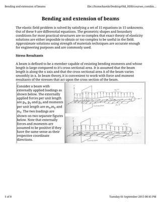
- 1. Bending and extension of beams The elastic field problem is solved by satisfying a set of 15 equations in 15 unknowns. Out of these 9 are differential equations. The geometric shapes and boundary conditions for most practical structures are so complex that exact theory of elasticity solutions are either imposible to obtain or too complex to be useful in the field. Approximate solutions using strength of materials techniques are accurate enough for engineering purposes and are commonly used. Stress Resultants A beam is defined to be a member capable of resisting bending moments and whose length is large compared to it's cross sectional area. It is assumed that the beam length is along the x axis and that the cross sectional area A of the beam varies smoothly in x. In beam theory, it is convenient to work with force and moment resultants of the stresses that act upon the cross section of the beam. Consider a beam with externally applied loadings as shown below. The externally applied forces per unit length are px, py and pz and moments per unit length are mx,my and mz. The two loadings are shown on two separate figures below. Note that externally forces and moments are assumed to be positive if they have the same sense as their respective coordinate directions. Bending and extension of beams file:///home/kamle/Desktop/Old_HDD/courses_combin... 1 of 8 Tuesday 01 September 2015 08:45 PM
- 2. Now suppose that a cutting plane is passed through the beam at a distance x from the origin and a free body diagram is constructed as shown. In general, six internal resultants can be constructed at the intersection of the x axis with the cross section defined by the cutting plane. On element area dA, Force=dF̂ dF̂= σxxdA îx + σxydA îy + σxzdA îz Total force on face = ∫ (σxxdA îx + σxydA îy + σxzdA îz) or, F̂=(P îx+ Vy îy+ Vz îz) Due to element are dA, the moment dM̂ is dM̂= r̂ × dF̂ The total moment on the face is the integral of this value. M̂=(Mx îx+ My îy+ Mz îz) The six stress resultants can now be written as: Axial Force P = ∫ σxxdA Shear Force Vy = ∫ σxydA Shear Force Vz = ∫ σxzdA Torsional Moment Mx = ∫ (yσxz-zσxy)dA Bending Moment My = ∫ zσxxdA Bending Moment Mz = ∫ (-yσxx)dA The face on which these internal resultants act is called a positive face because the x coordinate axis is coming out of it. Internal resultants are defined to be positive when Bending and extension of beams file:///home/kamle/Desktop/Old_HDD/courses_combin... 2 of 8 Tuesday 01 September 2015 08:45 PM
- 3. they act in their respective coordinate axis directions on a positive face. Linear Differential equations of equilibrium For the beam shown in the above figure subjected to externally applied forces per unit length px, py and pz and moments per unit length mx,my and mz, the differential equations of equilibrium can be written as: dP/dx = -px dVy/dx = -py dVz/dx = -pz dMx/dx = -mx dMy/dx = -my + Vz(x) dMz/dx = -mz - Vy(x) The above equations satisfy the equilibrium equations only in an average sense over the cross section. The above equations can be solved if the boundary conditions are known. Stresses due to extension and bending Normal stresses σxx are developed in the x coordinate direction due to the axial loading P and bending moments My and Mz. We will be making the following assumptions (called Bernoulli Euler assumptions): The transverse components of normal stress σyy and σzz are assumed to be negligible compared to the axial stress σxx. Cross sections are assumed to remain planar and normal to the Bending and extension of beams file:///home/kamle/Desktop/Old_HDD/courses_combin... 3 of 8 Tuesday 01 September 2015 08:45 PM
- 4. centroidal axis of deformation. It can be seen that the axial displacement u(x,y,z) is the sum of the contributions due to the axial extension u0=u(x,0,0), rotation due to bending about the z and y axes respectively: u(x,y,z)=u0 - θz(x)y + θy(x)z The axial strain εxx is given by: εxx= ∂u/∂x = du0/dx -y dθz/dx + z dθy/dx Consider a beam whose material properties are hetrogenous. Substitution in linear elastic stress strain equations gives: σxx= E (du0/dx -y dθz/dx + z dθy/dx) Substitution into resultant equations gives: Bending and extension of beams file:///home/kamle/Desktop/Old_HDD/courses_combin... 4 of 8 Tuesday 01 September 2015 08:45 PM
- 5. P = ∫E (du0/dx -y dθz/dx + z dθy/dx) dA My = ∫E (du0/dx -y dθz/dx + z dθy/dx) z dA Mz = - ∫E (du0/dx -y dθz/dx + z dθy/dx) ydA Now define the modulus weighted section properties as follows: A* = dA ȳ* = y dA z̄* = z dA I* yy = z2 dA I* yz = yz dA I* zz = y2 dA In the case of a homogeneous beam, the reference modulus E1 may be chosen to be the same as actual material modulus. In heterogeneous beams, the modulus weighted centroidal axes(x*,y*,z*) should be used. If the modulus weighted centroidal axes are chosen, then ȳ* and z̄* defined above will be identically zero. With such a choice, the equations become: du0/dx = P/ (E1 A*) dθz/dx = (MzI* yy+MyI* yz)/ (E1(I* yyI* zz- I* yz 2)) dθy/dx = (MyI* zz+MzI* yz)/ (E1(I* yyI* zz- I* yz 2)) Substituting these results into the strain equations gives: εxx = P/ (E1 A*) -y (MzI* yy+MyI* yz)/ (E1(I* yyI* zz- I* yz 2)) Bending and extension of beams file:///home/kamle/Desktop/Old_HDD/courses_combin... 5 of 8 Tuesday 01 September 2015 08:45 PM
- 6. +z (MyI* zz+MzI* yz)/ (E1(I* yyI* zz- I* yz 2)) σxx = E P/ (E1 A*) -y E(MzI* yy+MyI* yz)/ (E1(I* yyI* zz- I* yz 2)) +z E(MyI* zz+MzI* yz)/ (E1(I* yyI* zz- I* yz 2)) Determination of modulus weighted section properties Consider a beam composed of n discrete portions of homogeneous make up. In this case the equations for A* etc. reduce to: A* = Ei/E1 dA or, A* = dA or, A*= Ai Also, ȳ* = y dA or, ȳ'* = ȳi'Ai Similarly z̄* = z dA or, z̄'* = z̄i'Ai where ȳi' and z̄i' are the coordinates of the ith portion taken with respect to the arbitrary y' and z' axes. The modulus weighted moments of inertia may be determined about the modulus weighted centroid, or alternatively, we can determine these properties about the arbitrary y' and z' axes and then use the parallel axis theorem. Bending and extension of beams file:///home/kamle/Desktop/Old_HDD/courses_combin... 6 of 8 Tuesday 01 September 2015 08:45 PM
- 7. I* yy = I* y'y' - (z̄'*)2 A* I* yz = I* y'z' - (ȳ'*)(z̄*') A* I* zz = I* z'z' - (ȳ'*)2 A* Example Problem 1 The figure below shows an unsymmetrical beam section composed of four stringers a,b,c,d of equal area 0.1 sq. inch connected by a thin web. Determine stress and total load on each stringer if the moments applied on the section are My=10,000 lb-in and Mz=5000 lb-in. Example Problem 2 An airfoil is idealized as prismatic with average cross section shown below. All stringers are made of structural steel (E= 30 X 106 psi) with dimensions shown below. All skins are Aluminum(E=10 X 106 psi). determine the modulus weighted section properties assuming E1= 10 X 106 psi. Bending and extension of beams file:///home/kamle/Desktop/Old_HDD/courses_combin... 7 of 8 Tuesday 01 September 2015 08:45 PM
- 8. Example Problem 3 The idealized airfoil described in the previous example is subjected to the loading shown. Determine the stresses in the stringers at x=0. Deformations due to bending and extension It is possible to determine u(x,y,z), v(x,y,z) and w(x,y,z) at various points in the beam. It is of practical importance to determine the three displacement components along the centroidal axes i.e. u(x,0,0),v(x,0,0) and w(x,0,0).The axial component u0= u(x,0,0) can be ontained as: du0/dx = P/(E1 A*) To obtain v0 and w0, we use the relations : dθz/dx = d2v0/dx2 dθy/dx = d2w0/dx2 The above equations containing the variables u0,v0,w0 can be solved by integrating directly after applying displacement boundary conditions to account for integration constants. Bending and extension of beams file:///home/kamle/Desktop/Old_HDD/courses_combin... 8 of 8 Tuesday 01 September 2015 08:45 PM