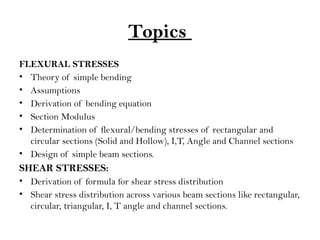
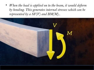
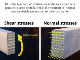
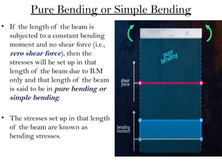
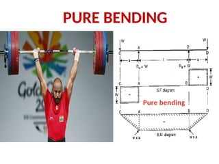
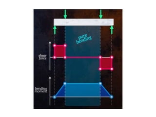
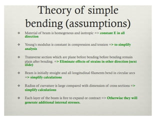
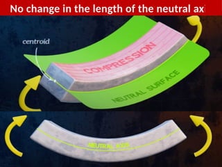
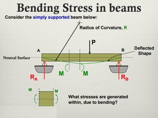
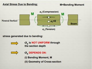
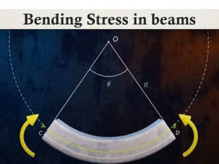
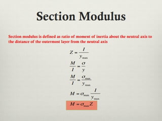
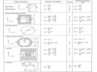
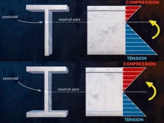
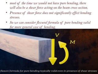
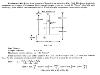
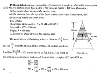
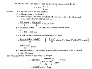
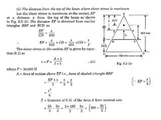
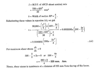
FLEXURAL STRESSES
&
SHEAR STRESSES
UNIT - II
Topics
FLEXURAL STRESSES
• Theory of simple bending
• Assumptions
• Derivation of bending equation
• Section Modulus
• Determination of flexural/bending stresses of rectangular and
circular sections (Solid and Hollow), I,T, Angle and Channel sections
• Design of simple beam sections.
SHEAR STRESSES:
• Derivation of formula for shear stress distribution
• Shear stress distribution across various beam sections like rectangular,
circular, triangular, I, T angle and channel sections.
• When the load is applied on to the beam, it would deform
by bending. This generates internal stresses which can be
represented by a SF(V) and BM(M)..
SF is the resultant of vertical shear stresses which acts
parallel to cross section. BM is the resultant of normal
stresses which acts normal to the cross section
Shear stresses Normal stresses
Pure Bending or Simple Bending
• If the length of the beam is
subjected to a constant bending
moment and no shear force (i.e.,
zero shear force), then the
stresses will be set up in that
length of the beam due to B.M
only and that length of the beam
is said to be in pure bending or
simple bending.
• The stresses set up in that length
of the beam are known as
bending stresses.
Pure bending
PURE BENDING
No change in the length of the neutral axis
• ∫y X dA represents the moment of entire area of the section
about NA. But we know that moment of any area about an
axis passing through its centroid, is equal to zero. Hence NA
coincides with the centroidal axis. Thus the centroidal
axis of a section gives the position of neutral axis.
Moment of Resistance
• Due to pure bending, the layers above NA are
subjected to compressive stresses and the layers
below are subjected to tensile stresses.
• Due to these stresses, forces will be acting on
the layers. These forces will have moment about
the NA. Total moment of these forces about the
NA for a section is known as Moment of
Resistance.
• The force on the layer at a distance y from NA is
• = (E/R) X y X dA
• Moment of this force about NA
• = force on layer X y
• = (E/R) X y X dA X y
• (E/R) X y2
X dA
Moment of
Resistance
• Total moment of forces on the section of the
beam,
• = ∫(E/R) X y2
X dA
• = (E/R) ∫ y2
X dA
Let M = external moment applied on the
beam section.
• For equilibrium the moment of resistance offered
by the section should be equal to the external
bending moment.
M = (E/R) ∫ y2
X dA
• But ∫y2
X dA represents the moment of
inertia of the area of the section about NA.
let this MOI be I.
• M = (E/R) I or I
M
R
E

• = My/I
σ Flexure formula
• It says that bending stress varies linearly as
the B.M in the distance increase and it
decreases as the area moment of inertia
increases.
• The maximum bending stress occurs on the
fibers those are farthest from the neutral axis.
i.e., y.
σmax = Mymax/I
I/Ymax depends on geometry of the section and
is called section modulus.
• most of the time we would not have pure bending, there
will also be a shear force acting on the beam cross section.
• Presence of shear force does not significantly effect bending
stresses.
• So we can consider flexural formula of pure bending valid
for more general case of bending.
• The shear force V is the resultant of shear stresses which are vertically
parallel to the cross section.
• we denote shear stresses using τ.
• To maintain equilibrium , these vertical shear stresses have complementary
horizontal shear stresses which act between horizontal layers of the beam as
shown in figure.
Consider a beam made of several planks. When the load is
applied , there is a tendency to the planks to slide relative to
one another
Now if the glue is applied between the planks and made it into a
single beam and load is applied. Now the planks will not slide and
this leads to the generation of horizontal stresses between them.
If instead of vertical force if we apply moment then
sliding of the planks will not occur and this case
would become pure bending condition. No
horizontal stresses would exist.
LOAD
Presence of
these horizontal
shear stresses
explains why
wooden beams
some times fail
longitudinally.
HORIZONTAL SHEAR FAILURE
shear stress is distributed uniformly across the cross section of
the beam. Shear stresses has to be zero at top and bottom free
surfaces of the beam. So the average shear stress isn’t very
useful
Shear stress at a section
• Simply supported beam with udl.
• For udl SF and BM will vary along the length of the beam
• Consider two sections AB and CD as shown.
• Let it is required to find the shear stress on the section AB at a distance y1
from the NA.
• On the cross section of the beam let EF be the line at a distance y1 from the
NA.
• Part of the beam above EF and between AB and CD.
• This part of beam may be taken to consist of infinite number of elemental
cylinders each of area dA and length dx. Consider one such cylinder y from
NA.
dA = area of elemental cylinder
dx = length of elemental cylinder
y = distance of elemental cylinder from NA
= intensity of bending stress on the end of the elemental
σ
cylinder on the section AB.
+ d = intensity of bending stress on the end of the
σ σ
elemental cylinder on the section CD.
Let at the section CD,
F + dF = Shear Force
M + dM = Bending Moment
Let at the section AB,
F = Shear Force
M = Bending Moment
• Bending stress on section AB,
= My/I
σ
• Bending stress on section CD,
+ d = (M + dM)y/I
σ σ
• Force on AB = X dA
σ
= (My/I) X dA
• Force on CD similarly
= ((M + dM)y/I) X dA
• Forces on the ends of elemental cylinder are different. Hence there will
be unbalanced force on the elemental cylinder.
∴ net unbalanced force on the elemental cylinder
= ((M + dM)y/I) X dA - (My/I) X dA
= (dM/I) X y X dA
∴ total unbalanced force above EF = ∫ (dM/I) X y X dA
= (dM/I) ∫ y X dA
= (dM/I) X A X y
̅
A = area of section above the level EF i.e., EFGH
= distance of the C.G of the area A from the NA.
y
̅
• Due the total unbalanced force above EF, the beam may fail due
to shear. In order the above part may not fail, the horizontal
section of the beam at level EF must offer a shear resistance.
• This shear resistance at least must be equal to total unbalanced
force to avoid failure due to shear.
•
Shear resistance at level EF = Total unbalanced force
Shear force = τ X b X dx
= intensity of horizontal shear at the level EF
τ
b = width of beam at level EF
τ X b X dx = (dM/I) X A X y
̅
τ = (dM/dx).A /Ib
y
̅
τ = F. (A /Ib)
y
̅ since (dM/dx) = shear force =
F.
• The shear stress given by above equation is the horizontal shear
stress at the distance y1 from the neutral axis. But by the principal
of complementary shear, the horizontal shear stress is accompanied
by a vertical shear stress τ of the same quantity
Shear stress distribution for different sections
Rectangular section:
= F. (A /Ib)
τ y
̅
A = ((d/2)-y) X b
= y + (1/2)((d/2) – y)
y
̅
Substituting above values,
= F/2I((d
τ 2
/4) – y2
)
At top edge, y = d/2, =0;
τ
At neutral axis, y = 0,
=Fd
τ 2
/8I or 1.5F/bd
τavg = F/bd
τmax = 1.5 τavg
Shear stress distribution for different sections
Circular section:
= F. (A /Ib)
τ y
̅
dA = b X dy = EF X dy
= 2 X EB X dy
= 2 X √ (R2
– y2
) X dy
Moment of this area
about NA = y X dA
= 2y √ (R2
– y2
) dy
Moment of whole shaded
area about NA is obtained
by integrating above equation
between y and R.
We get,
Ay̅ = 2/3(R2
– y2
) 3/2
Substituting above value, we get
= F/3I (R
τ 2
– y2
)
At neutral axis, y = 0, =FR
τ 2
/3I or 4F/3∏R2
τavg = F/ ∏R2
τmax = 4/3 τavg
Shear stress distribution for an I - Section
i. Shear stress distribution
in the flange:
= F/2I((d
τ 2
/4) – y2
)
a. For upper edge of flange
y = d/2, = 0;
τ
b. For the lower edge of flange
y = d/2, = F/8I(D
τ 2
– d2
)
i. Shear stress distribution
in the web:
At neutral axis, y = 0, shear stress
is maximum.
At the junction of top of the
web and bottom of flange,
y=d/2
• The shear stress at the junction of flange and web
changes abruptly from equations
= F/8I(D
τ 2
– d2
)
to
= FB/8bI(D
τ 2
– d2
)
THANK YOU!

Flexural STRENGTH unit-200715014624.pptx

  • 1.
  • 2.
    Topics FLEXURAL STRESSES • Theoryof simple bending • Assumptions • Derivation of bending equation • Section Modulus • Determination of flexural/bending stresses of rectangular and circular sections (Solid and Hollow), I,T, Angle and Channel sections • Design of simple beam sections. SHEAR STRESSES: • Derivation of formula for shear stress distribution • Shear stress distribution across various beam sections like rectangular, circular, triangular, I, T angle and channel sections.
  • 3.
    • When theload is applied on to the beam, it would deform by bending. This generates internal stresses which can be represented by a SF(V) and BM(M)..
  • 4.
    SF is theresultant of vertical shear stresses which acts parallel to cross section. BM is the resultant of normal stresses which acts normal to the cross section Shear stresses Normal stresses
  • 6.
    Pure Bending orSimple Bending • If the length of the beam is subjected to a constant bending moment and no shear force (i.e., zero shear force), then the stresses will be set up in that length of the beam due to B.M only and that length of the beam is said to be in pure bending or simple bending. • The stresses set up in that length of the beam are known as bending stresses.
  • 7.
  • 10.
    No change inthe length of the neutral axis
  • 16.
    • ∫y XdA represents the moment of entire area of the section about NA. But we know that moment of any area about an axis passing through its centroid, is equal to zero. Hence NA coincides with the centroidal axis. Thus the centroidal axis of a section gives the position of neutral axis.
  • 17.
    Moment of Resistance •Due to pure bending, the layers above NA are subjected to compressive stresses and the layers below are subjected to tensile stresses. • Due to these stresses, forces will be acting on the layers. These forces will have moment about the NA. Total moment of these forces about the NA for a section is known as Moment of Resistance. • The force on the layer at a distance y from NA is • = (E/R) X y X dA • Moment of this force about NA • = force on layer X y • = (E/R) X y X dA X y • (E/R) X y2 X dA
  • 18.
  • 19.
    • Total momentof forces on the section of the beam, • = ∫(E/R) X y2 X dA • = (E/R) ∫ y2 X dA Let M = external moment applied on the beam section. • For equilibrium the moment of resistance offered by the section should be equal to the external bending moment. M = (E/R) ∫ y2 X dA • But ∫y2 X dA represents the moment of inertia of the area of the section about NA. let this MOI be I. • M = (E/R) I or I M R E 
  • 21.
    • = My/I σFlexure formula • It says that bending stress varies linearly as the B.M in the distance increase and it decreases as the area moment of inertia increases. • The maximum bending stress occurs on the fibers those are farthest from the neutral axis. i.e., y. σmax = Mymax/I I/Ymax depends on geometry of the section and is called section modulus.
  • 25.
    • most ofthe time we would not have pure bending, there will also be a shear force acting on the beam cross section. • Presence of shear force does not significantly effect bending stresses. • So we can consider flexural formula of pure bending valid for more general case of bending.
  • 36.
    • The shearforce V is the resultant of shear stresses which are vertically parallel to the cross section. • we denote shear stresses using τ. • To maintain equilibrium , these vertical shear stresses have complementary horizontal shear stresses which act between horizontal layers of the beam as shown in figure.
  • 38.
    Consider a beammade of several planks. When the load is applied , there is a tendency to the planks to slide relative to one another
  • 39.
    Now if theglue is applied between the planks and made it into a single beam and load is applied. Now the planks will not slide and this leads to the generation of horizontal stresses between them.
  • 42.
    If instead ofvertical force if we apply moment then sliding of the planks will not occur and this case would become pure bending condition. No horizontal stresses would exist.
  • 43.
    LOAD Presence of these horizontal shearstresses explains why wooden beams some times fail longitudinally. HORIZONTAL SHEAR FAILURE
  • 44.
    shear stress isdistributed uniformly across the cross section of the beam. Shear stresses has to be zero at top and bottom free surfaces of the beam. So the average shear stress isn’t very useful
  • 45.
    Shear stress ata section • Simply supported beam with udl. • For udl SF and BM will vary along the length of the beam • Consider two sections AB and CD as shown.
  • 46.
    • Let itis required to find the shear stress on the section AB at a distance y1 from the NA. • On the cross section of the beam let EF be the line at a distance y1 from the NA. • Part of the beam above EF and between AB and CD. • This part of beam may be taken to consist of infinite number of elemental cylinders each of area dA and length dx. Consider one such cylinder y from NA. dA = area of elemental cylinder dx = length of elemental cylinder y = distance of elemental cylinder from NA = intensity of bending stress on the end of the elemental σ cylinder on the section AB. + d = intensity of bending stress on the end of the σ σ elemental cylinder on the section CD. Let at the section CD, F + dF = Shear Force M + dM = Bending Moment Let at the section AB, F = Shear Force M = Bending Moment
  • 47.
    • Bending stresson section AB, = My/I σ • Bending stress on section CD, + d = (M + dM)y/I σ σ • Force on AB = X dA σ = (My/I) X dA • Force on CD similarly = ((M + dM)y/I) X dA • Forces on the ends of elemental cylinder are different. Hence there will be unbalanced force on the elemental cylinder. ∴ net unbalanced force on the elemental cylinder = ((M + dM)y/I) X dA - (My/I) X dA = (dM/I) X y X dA ∴ total unbalanced force above EF = ∫ (dM/I) X y X dA = (dM/I) ∫ y X dA = (dM/I) X A X y ̅ A = area of section above the level EF i.e., EFGH = distance of the C.G of the area A from the NA. y ̅
  • 48.
    • Due thetotal unbalanced force above EF, the beam may fail due to shear. In order the above part may not fail, the horizontal section of the beam at level EF must offer a shear resistance. • This shear resistance at least must be equal to total unbalanced force to avoid failure due to shear. •
  • 49.
    Shear resistance atlevel EF = Total unbalanced force Shear force = τ X b X dx = intensity of horizontal shear at the level EF τ b = width of beam at level EF τ X b X dx = (dM/I) X A X y ̅ τ = (dM/dx).A /Ib y ̅ τ = F. (A /Ib) y ̅ since (dM/dx) = shear force = F. • The shear stress given by above equation is the horizontal shear stress at the distance y1 from the neutral axis. But by the principal of complementary shear, the horizontal shear stress is accompanied by a vertical shear stress τ of the same quantity
  • 57.
    Shear stress distributionfor different sections Rectangular section: = F. (A /Ib) τ y ̅ A = ((d/2)-y) X b = y + (1/2)((d/2) – y) y ̅ Substituting above values, = F/2I((d τ 2 /4) – y2 ) At top edge, y = d/2, =0; τ At neutral axis, y = 0, =Fd τ 2 /8I or 1.5F/bd τavg = F/bd τmax = 1.5 τavg
  • 58.
    Shear stress distributionfor different sections Circular section: = F. (A /Ib) τ y ̅ dA = b X dy = EF X dy = 2 X EB X dy = 2 X √ (R2 – y2 ) X dy Moment of this area about NA = y X dA = 2y √ (R2 – y2 ) dy Moment of whole shaded area about NA is obtained by integrating above equation between y and R. We get, Ay̅ = 2/3(R2 – y2 ) 3/2 Substituting above value, we get = F/3I (R τ 2 – y2 ) At neutral axis, y = 0, =FR τ 2 /3I or 4F/3∏R2 τavg = F/ ∏R2 τmax = 4/3 τavg
  • 59.
    Shear stress distributionfor an I - Section
  • 60.
    i. Shear stressdistribution in the flange: = F/2I((d τ 2 /4) – y2 ) a. For upper edge of flange y = d/2, = 0; τ b. For the lower edge of flange y = d/2, = F/8I(D τ 2 – d2 )
  • 61.
    i. Shear stressdistribution in the web: At neutral axis, y = 0, shear stress is maximum. At the junction of top of the web and bottom of flange, y=d/2
  • 62.
    • The shearstress at the junction of flange and web changes abruptly from equations = F/8I(D τ 2 – d2 ) to = FB/8bI(D τ 2 – d2 )
  • 66.