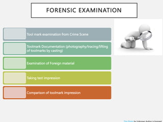
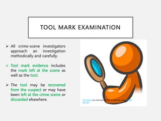
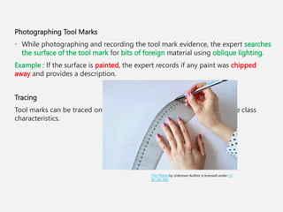
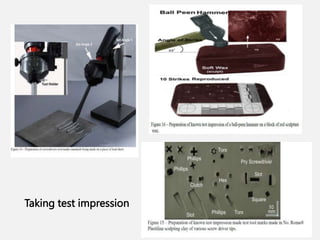
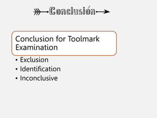
TOOLMARK IMPRESSIONS
TOOL MARKS IMPRESSIONS
This Photo by Unknown Author is licensed under CC BY-SA
 Tool
 Toolmark
TOOL SURFACE
CHARACTERISTICS
Class characteristics
Subclass
characteristics
Individual
characteristics
FORENSIC SIGNIFICANCE OF TOOL MARKS
TYPES OF TOOL MARKS
Compression type marks/Indentation marks
Striated marks/Abrasion marks
Cutting marks
Combination of compression and striated marks
Source: RG Nichols 2000
Cutting marks
Source: RG Nichols 2000
Combination of compression
and striated marks
FORENSIC EXAMINATION
Tool mark examination from Crime Scene
Toolmark Documentation (photography/tracing/lifting
of toolmarks by casting)
Examination of Foreign material
Taking test impression
Comparison of toolmark impression
TOOL SURFACE
CHARACTERISTICS
• Tools have unique characteristics
resulting from manufacturing processes
and from use over time.
• Nicks, ridge marks, and blemishes may
develop on the striking surface of the
tool.
• These unique characteristics from
natural wear and tear can affect
impressions made by the tools, making
them unique as well.
• Other factors are oxidation or rusting of
tools and uneven sharpening.
TOOL MARK EXAMINATION
 All crime-scene investigators
approach an investigation
methodically and carefully.
 Tool mark evidence includes
the mark left at the scene as
well as the tool.
 The tool may be recovered
from the suspect or may have
been left at the crime scene or
discarded elsewhere. This Photo by Unknown Author is licensed under CC BY-
NC-ND
DOCUMENTING THE EVIDENCE
• The best way to document tools and tool mark
evidence is to use photography.
• All evidence is photographed with a measuring
device to show the appropriate scale for
reference.
Photographing Tools
• When photographing a tool, experts focus on
any scratches or gouges on the surface.
• Oblique lighting is preferred to direct lighting
because it casts shadows and highlights details
that are not easily visible under direct lighting.
• Magnesium smoking is often used on dark-
colored tools.
In this method, magnesium ribbon is burned, which
produces a white, powdery film of magnesium
oxide that coats the surface of the tool. Coating the
tool highlights the detail during photography.
Photographing Tool Marks
• While photographing and recording the tool mark evidence, the expert searches
the surface of the tool mark for bits of foreign material using oblique lighting.
Example : If the surface is painted, the expert records if any paint was chipped
away and provides a description.
Tracing
Tool marks can be traced on a tracing paper. This helps in comparing the class
characteristics.
This Photo by Unknown Author is licensed under CC
BY-NC-ND
CASTING IMPRESSIONS
 The crime scene investigator may actually
cut a part from the door or door jamb
that contains tool mark evidence.
 If this is not possible, casting is a
commonly used method of preserving
impressions of the tool marks.
 The cast impression will retain the unique
indentation marks made by a specific tool.
 Plastic/rubber, plaster of Paris, dental
cast, metal casting, cellulose acetate
 dusted for fingerprints (magnetic
dusting powder and silicone material )
 the size of the impression
This Photo by Unknown Author is licensed under CC BY-
SA
Taking test impression
 The material for test impression must be soft
soft enough so that the tool edge will not be
altered (modeling wax )
 When the original mark is in wood, paint or
soft metal, hard metal such as steel or brass
the standard should be made with a similar
material.
 In cases involving wire cutters the test tool
marks can be cable made from copper or
aluminum.
 Several test impressions should be made at
various angles with the tool.
Taking test impression
Comparison of tool marks
 A tool mark must be compared with tool mark, mould with mould and photograph wit
photograph having same magnification.
 The comparison is best done by using comparison microscope and with oblique
illumination.
 Magnification of test and crime sample should be identical.
This Photo by Unknown Author is licensed under CC BY
Source: RG Nichols 2000
Comparison of tool marks
Source: RG Nichols 2000
Comparison of tool marks
Conclusion for Toolmark
Examination
• Exclusion
• Identification
• Inconclusive
F O RENSIC S CI ENCE UG
S E M ESTER V
FORENSIC PHYSICS AND
BALLISTICS
This Photo by Unknown Author is licensed under CC BY-SA
COLLECTING AND PRESERVING
A SAMPLE
• All evidence is carefully transported to the forensic laboratory to protect it
from damage.
• When tools are found, they are collected and packaged separately in
containers or boxes and then taken to a laboratory for analysis.
• The object containing the tool mark or the actual impression cast is also
packaged in a container or box and taken to the laboratory.
• Small objects may be wrapped with clean paper and placed in small
containers or plastic bags, while larger objects can be packed in cartons or
boxes.
• All evidence must also be correctly labelled and processed.
Photo 1-2 Pipe with tool marks. The spacing between tool
marks on the pipe is 4 mm apart.
Case 1 - Pipe and Vise
Grip Arson
Investigation
Evidence Submitted:
Evidence collected at
the scene of a possible
arson investigation.
One vise grip
Request: Could the vise
grip obtained from the
suspect’s auto been
recently used to loosen
the two
sections of gas pipe
found at the scene of a
suspected arson?
Spacing between teeth
tool marks on the pipe
are 4 mm apart.
Case 2 – Gas Explosion Homicide Investigation
A landlord had been unsuccessfully trying to evict an old woman from her rent
controlled apart for years. A gas explosion occurred at the location and the old woman
was killed. The arson investigator suspected foul play, obtained two search warrants,
and searches the building’s basement and the landlord’s home.
Evidence Submitted: Two sections of gas pipes (building’s basement where the
explosion ) and (landlord’s basement)of gas pipes with apparent tool marks .
Request: Determine if the tool marks on the known gas pipe (K-2a) were consistent
with the tool marks present on the questioned gas pipe (Q-1a).
Photo 5-1 Two gas pipes, one (Q-1a) from the scene of a homicide and gas explosion investigation,
and one gas pipe with known tool marks made with a wrench from the landlord’s basement (pipe
marked K-2a).
Photo:
Comparison microscope
photomicrograph showing
one tooth mark on the K-2a
pipe overlapped with
one tooth mark on the Q-1a
pipe (accidental striation)
Photo :
comparison of the
linear and angular
dimensions
(Steriomicrope
Observations)
This Photo by Unknown Author is licensed under CC BY-SA

Unit2_Toolmark impressions.pptx

  • 1.
  • 2.
    TOOL MARKS IMPRESSIONS ThisPhoto by Unknown Author is licensed under CC BY-SA  Tool  Toolmark
  • 3.
  • 4.
  • 6.
    TYPES OF TOOLMARKS Compression type marks/Indentation marks Striated marks/Abrasion marks Cutting marks Combination of compression and striated marks
  • 7.
    Source: RG Nichols2000 Source: RG Nichols 2000 Cutting marks
  • 8.
    Source: RG Nichols2000 Combination of compression and striated marks
  • 9.
    FORENSIC EXAMINATION Tool markexamination from Crime Scene Toolmark Documentation (photography/tracing/lifting of toolmarks by casting) Examination of Foreign material Taking test impression Comparison of toolmark impression
  • 10.
    TOOL SURFACE CHARACTERISTICS • Toolshave unique characteristics resulting from manufacturing processes and from use over time. • Nicks, ridge marks, and blemishes may develop on the striking surface of the tool. • These unique characteristics from natural wear and tear can affect impressions made by the tools, making them unique as well. • Other factors are oxidation or rusting of tools and uneven sharpening.
  • 11.
    TOOL MARK EXAMINATION All crime-scene investigators approach an investigation methodically and carefully.  Tool mark evidence includes the mark left at the scene as well as the tool.  The tool may be recovered from the suspect or may have been left at the crime scene or discarded elsewhere. This Photo by Unknown Author is licensed under CC BY- NC-ND
  • 12.
    DOCUMENTING THE EVIDENCE •The best way to document tools and tool mark evidence is to use photography. • All evidence is photographed with a measuring device to show the appropriate scale for reference. Photographing Tools • When photographing a tool, experts focus on any scratches or gouges on the surface. • Oblique lighting is preferred to direct lighting because it casts shadows and highlights details that are not easily visible under direct lighting. • Magnesium smoking is often used on dark- colored tools. In this method, magnesium ribbon is burned, which produces a white, powdery film of magnesium oxide that coats the surface of the tool. Coating the tool highlights the detail during photography.
  • 13.
    Photographing Tool Marks •While photographing and recording the tool mark evidence, the expert searches the surface of the tool mark for bits of foreign material using oblique lighting. Example : If the surface is painted, the expert records if any paint was chipped away and provides a description. Tracing Tool marks can be traced on a tracing paper. This helps in comparing the class characteristics. This Photo by Unknown Author is licensed under CC BY-NC-ND
  • 14.
    CASTING IMPRESSIONS  Thecrime scene investigator may actually cut a part from the door or door jamb that contains tool mark evidence.  If this is not possible, casting is a commonly used method of preserving impressions of the tool marks.  The cast impression will retain the unique indentation marks made by a specific tool.  Plastic/rubber, plaster of Paris, dental cast, metal casting, cellulose acetate  dusted for fingerprints (magnetic dusting powder and silicone material )  the size of the impression This Photo by Unknown Author is licensed under CC BY- SA
  • 15.
    Taking test impression The material for test impression must be soft soft enough so that the tool edge will not be altered (modeling wax )  When the original mark is in wood, paint or soft metal, hard metal such as steel or brass the standard should be made with a similar material.  In cases involving wire cutters the test tool marks can be cable made from copper or aluminum.  Several test impressions should be made at various angles with the tool.
  • 16.
  • 17.
    Comparison of toolmarks  A tool mark must be compared with tool mark, mould with mould and photograph wit photograph having same magnification.  The comparison is best done by using comparison microscope and with oblique illumination.  Magnification of test and crime sample should be identical. This Photo by Unknown Author is licensed under CC BY
  • 18.
    Source: RG Nichols2000 Source: RG Nichols 2000 Comparison of tool marks
  • 19.
    Source: RG Nichols2000 Source: RG Nichols 2000 Comparison of tool marks
  • 20.
    Conclusion for Toolmark Examination •Exclusion • Identification • Inconclusive
  • 21.
    F O RENSICS CI ENCE UG S E M ESTER V FORENSIC PHYSICS AND BALLISTICS
  • 22.
    This Photo byUnknown Author is licensed under CC BY-SA
  • 23.
    COLLECTING AND PRESERVING ASAMPLE • All evidence is carefully transported to the forensic laboratory to protect it from damage. • When tools are found, they are collected and packaged separately in containers or boxes and then taken to a laboratory for analysis. • The object containing the tool mark or the actual impression cast is also packaged in a container or box and taken to the laboratory. • Small objects may be wrapped with clean paper and placed in small containers or plastic bags, while larger objects can be packed in cartons or boxes. • All evidence must also be correctly labelled and processed.
  • 24.
    Photo 1-2 Pipewith tool marks. The spacing between tool marks on the pipe is 4 mm apart. Case 1 - Pipe and Vise Grip Arson Investigation Evidence Submitted: Evidence collected at the scene of a possible arson investigation. One vise grip Request: Could the vise grip obtained from the suspect’s auto been recently used to loosen the two sections of gas pipe found at the scene of a suspected arson?
  • 25.
    Spacing between teeth toolmarks on the pipe are 4 mm apart.
  • 26.
    Case 2 –Gas Explosion Homicide Investigation A landlord had been unsuccessfully trying to evict an old woman from her rent controlled apart for years. A gas explosion occurred at the location and the old woman was killed. The arson investigator suspected foul play, obtained two search warrants, and searches the building’s basement and the landlord’s home. Evidence Submitted: Two sections of gas pipes (building’s basement where the explosion ) and (landlord’s basement)of gas pipes with apparent tool marks . Request: Determine if the tool marks on the known gas pipe (K-2a) were consistent with the tool marks present on the questioned gas pipe (Q-1a).
  • 27.
    Photo 5-1 Twogas pipes, one (Q-1a) from the scene of a homicide and gas explosion investigation, and one gas pipe with known tool marks made with a wrench from the landlord’s basement (pipe marked K-2a).
  • 28.
    Photo: Comparison microscope photomicrograph showing onetooth mark on the K-2a pipe overlapped with one tooth mark on the Q-1a pipe (accidental striation) Photo : comparison of the linear and angular dimensions (Steriomicrope Observations)
  • 29.
    This Photo byUnknown Author is licensed under CC BY-SA

Editor's Notes

  • #3 A tool is defined as an instrument that is designed to gain a mechanical advantage. It is also commonly thought of as being the harder of two objects that, when brought into forcible contact, will produce a mark on the softer object. Toolmark is Defined as a mark produced by a tool when that tool is brought into forcible contact with a surface against which the harder tool is used. Class characteristics: Measurable features of a tool that indicate a restricted group source. They are design features of a tool and are therefore determined before manufacture. Such features include size, the profile of the tool, the type of mark to be expected using the tool, and, sometimes, the direction of travel. Specific examples of class characteristics include the width of a screwdriver blade, the jaw width along with the number and spacing of serrated teeth on the jaws of a pipe wrench, and whether a cut is produced by two blades passing over each other such as the case with scissors or two blades cutting and pinching an object such as when bolt cutters are used.   Individual characteristics Those features are produced by the random imperfections and irregularities of tool surfaces against an object. These imperfections and irregularities are produced incidental to manufacture and are not intended by the manufacturer. They can be microscopic or large, such as when a portion of the tool surface breaks.