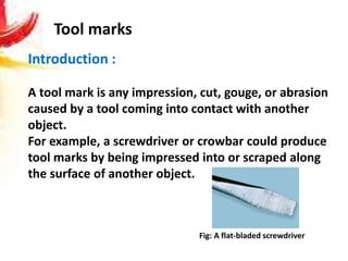
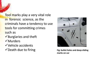
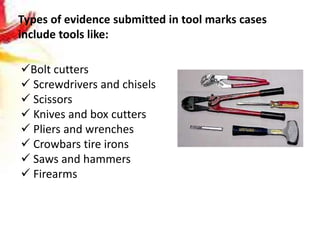
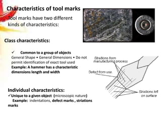
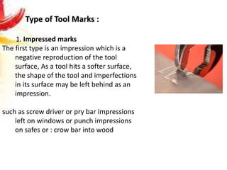
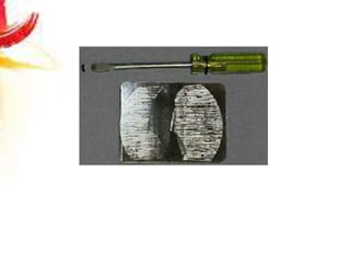
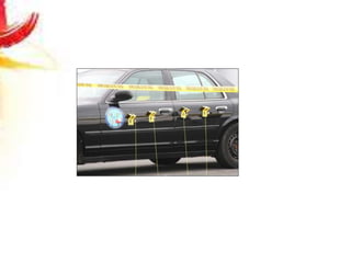
Tool Marks Examination and
Evaluation
Suryakant Mishra
Asst. Professor
Department of Zoology
& Forensic Science
Kurukshetra University, Kurukshetra
Introduction :
A tool mark is any impression, cut, gouge, or abrasion
caused by a tool coming into contact with another
object.
For example, a screwdriver or crowbar could produce
tool marks by being impressed into or scraped along
the surface of another object.
Tool marks
Fig: A flat-bladed screwdriver
Tool marks play a very vital role
in forensic science, as the
criminals have a tendency to use
tools for committing crimes
such as
Burglaries and theft
Murders
Vehicle accidents
Death due to firing Fig: bullet holes and deep sliding
marks on car
Types of evidence submitted in tool marks cases
include tools like:
Bolt cutters
 Screwdrivers and chisels
 Scissors
 Knives and box cutters
 Pliers and wrenches
 Crowbars tire irons
 Saws and hammers
 Firearms
Basis of tool marks identification:
Law of individuality
Locard’s exchange principle
Permanency
Tool marks have two different
kinds of characteristics:
Characteristics of tool marks
Class characteristics:
 Common to a group of objects
General Shape • General Dimensions • Do not
permit identification of exact tool used
Example: A hammer has a characteristic
dimensions length and width
Individual characteristics:
Unique to a given object (microscopic nature)
Example: indentations, defect marks , striations
marks
Type of Tool Marks :
1. Impressed marks
The first type is an impression which is a
negative reproduction of the tool
surface, As a tool hits a softer surface,
the shape of the tool and imperfections
in its surface may be left behind as an
impression.
such as screw driver or pry bar impressions
left on windows or punch impressions
on safes or : crow bar into wood
2. Abrasions/ scraps or striations marks:
Caused when a tool slides or scratches across another surface
which produces striated areas on the marked surface.
Occasionally impressions made by tools with striated surfaces
may resemble in appearance abrasion or
friction marks
Example: sliding a screw driver along the side of a car surface
3. Cutting (“crushed”) marks:
 Caused by pressure being
applied to both sides of an
object
Examples: pliers or wire
cutters
4. Repetitive cut marks
 Caused by repetitive actions
Example: a saw marks
5. Drill holes
Fig: repetitive cut
marks (saw marks)
Collection of Tool Mark Evidence
Step 1: Collection and recording
of tool marks form crime
scene :
a. Photography:
b. Casting methods of tool marks
collection
 Plaster of Paris
 Plasticine
 Latex and plastic solution
 Dental stone
 Wood metal
 Adhesive tape
Two types of photographs are needed for courtroom
identification.
• An over-all photo depicting the entire object which bears
the toolmark.
• A close-up photo showing the detail of the toolmark. This
close-up is for identification and orientation only and
cannot be used for actual comparisons.
• Photograph of tool marks should be taken with scale
Sharps packaging
The operating surfaces of suspect tools should
be protected and preserved.
The tool should be individually packaged and
identified with a string tag bearing the
information required by agency crime scene
search protocols.
If a tool is a sharp, especially a potentially
body fluid-contaminated sharp, it should be
packaged in a leak proof, puncture-resistant,
sealed container.
Source:
https://projects.nfstc.org/firearms/module06/fir_m06
_t06_05_f.htm
Plastic containers are generally useful for packaging evidence because
they can be sealed closed and permit observation of the contents.
However, they must not be used for packaging of biological evidence.
Biological evidence, such as blood-stained clothing or vegetation
suspected to be cannabis, should be packaged in paper containers
that allow airflow around the material.
Plastic is not recommended for packaging firearms evidence since any
moisture present could promote rusting of the item.
Step 2: Make test marks with the suspected
tool for comparison purpose:
 Similar surface material where tool mark was present
preferably used for collection of standards
 or Make a cast of the marks, usually with silicone rubber.
Comparison process:
1. Comparison of class characteristics- such as dimensions,
shape, length and width, depth.
2. Comparison of individual characteristics.
Examination and matching of tool marks:
1. Mechanical fit
2. Comparison microscope
3. Stereomicroscope
4. Striagraphy
5. Superimposition
Fig: Comparison microscope Fig: stereomicroscope
Comparison and matching of tool marks:
1. Physical match: mechanical fit
2. Side by side match
3. composite match
4. Superimposition
Fig: Side by side matching of fired
cartridges base marks
A comparison microscope is
used to perform the
comparison process.
 The unknown tool mark is
placed on the left side of the
microscope and the known
mark on the right side.
 If individual characteristics of
both tool marks match, the
common origin between the
unknown tool mark and the
tool is established.
Figure: composite match of striations marks on fired
bullets
Comparison photomicrograph of test sledge
hammer mark on lead (left) and hammer
mark on burglarized safe dial (right).
Forensic analysis of tool marks

Forensic analysis of tool marks

  • 1.
    Tool Marks Examinationand Evaluation Suryakant Mishra Asst. Professor Department of Zoology & Forensic Science Kurukshetra University, Kurukshetra
  • 2.
    Introduction : A toolmark is any impression, cut, gouge, or abrasion caused by a tool coming into contact with another object. For example, a screwdriver or crowbar could produce tool marks by being impressed into or scraped along the surface of another object. Tool marks Fig: A flat-bladed screwdriver
  • 3.
    Tool marks playa very vital role in forensic science, as the criminals have a tendency to use tools for committing crimes such as Burglaries and theft Murders Vehicle accidents Death due to firing Fig: bullet holes and deep sliding marks on car
  • 4.
    Types of evidencesubmitted in tool marks cases include tools like: Bolt cutters  Screwdrivers and chisels  Scissors  Knives and box cutters  Pliers and wrenches  Crowbars tire irons  Saws and hammers  Firearms
  • 5.
    Basis of toolmarks identification: Law of individuality Locard’s exchange principle Permanency
  • 6.
    Tool marks havetwo different kinds of characteristics: Characteristics of tool marks Class characteristics:  Common to a group of objects General Shape • General Dimensions • Do not permit identification of exact tool used Example: A hammer has a characteristic dimensions length and width Individual characteristics: Unique to a given object (microscopic nature) Example: indentations, defect marks , striations marks
  • 7.
    Type of ToolMarks : 1. Impressed marks The first type is an impression which is a negative reproduction of the tool surface, As a tool hits a softer surface, the shape of the tool and imperfections in its surface may be left behind as an impression. such as screw driver or pry bar impressions left on windows or punch impressions on safes or : crow bar into wood
  • 8.
    2. Abrasions/ scrapsor striations marks: Caused when a tool slides or scratches across another surface which produces striated areas on the marked surface. Occasionally impressions made by tools with striated surfaces may resemble in appearance abrasion or friction marks Example: sliding a screw driver along the side of a car surface
  • 9.
    3. Cutting (“crushed”)marks:  Caused by pressure being applied to both sides of an object Examples: pliers or wire cutters 4. Repetitive cut marks  Caused by repetitive actions Example: a saw marks 5. Drill holes Fig: repetitive cut marks (saw marks)
  • 10.
    Collection of ToolMark Evidence Step 1: Collection and recording of tool marks form crime scene : a. Photography: b. Casting methods of tool marks collection  Plaster of Paris  Plasticine  Latex and plastic solution  Dental stone  Wood metal  Adhesive tape
  • 11.
    Two types ofphotographs are needed for courtroom identification. • An over-all photo depicting the entire object which bears the toolmark. • A close-up photo showing the detail of the toolmark. This close-up is for identification and orientation only and cannot be used for actual comparisons. • Photograph of tool marks should be taken with scale
  • 12.
    Sharps packaging The operatingsurfaces of suspect tools should be protected and preserved. The tool should be individually packaged and identified with a string tag bearing the information required by agency crime scene search protocols. If a tool is a sharp, especially a potentially body fluid-contaminated sharp, it should be packaged in a leak proof, puncture-resistant, sealed container. Source: https://projects.nfstc.org/firearms/module06/fir_m06 _t06_05_f.htm
  • 13.
    Plastic containers aregenerally useful for packaging evidence because they can be sealed closed and permit observation of the contents. However, they must not be used for packaging of biological evidence. Biological evidence, such as blood-stained clothing or vegetation suspected to be cannabis, should be packaged in paper containers that allow airflow around the material. Plastic is not recommended for packaging firearms evidence since any moisture present could promote rusting of the item.
  • 14.
    Step 2: Maketest marks with the suspected tool for comparison purpose:  Similar surface material where tool mark was present preferably used for collection of standards  or Make a cast of the marks, usually with silicone rubber. Comparison process: 1. Comparison of class characteristics- such as dimensions, shape, length and width, depth. 2. Comparison of individual characteristics.
  • 15.
    Examination and matchingof tool marks: 1. Mechanical fit 2. Comparison microscope 3. Stereomicroscope 4. Striagraphy 5. Superimposition
  • 16.
    Fig: Comparison microscopeFig: stereomicroscope
  • 17.
    Comparison and matchingof tool marks: 1. Physical match: mechanical fit 2. Side by side match 3. composite match 4. Superimposition
  • 18.
    Fig: Side byside matching of fired cartridges base marks A comparison microscope is used to perform the comparison process.  The unknown tool mark is placed on the left side of the microscope and the known mark on the right side.  If individual characteristics of both tool marks match, the common origin between the unknown tool mark and the tool is established.
  • 19.
    Figure: composite matchof striations marks on fired bullets
  • 20.
    Comparison photomicrograph oftest sledge hammer mark on lead (left) and hammer mark on burglarized safe dial (right).