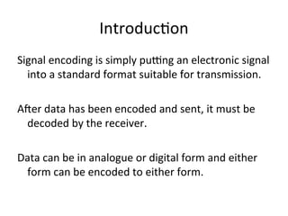
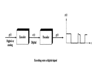
Introduction
Signal encoding issimply putting an electronic signal
into a standard format suitable for transmission.
After data has been encoded and sent, it must be
decoded by the receiver.
Data can be in analogue or digital form and either
form can be encoded to either form.
4.
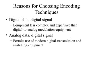
Reasons for ChoosingEncoding
Techniques
• Digital data, digital signal
– Equipment less complex and expensive than
digital-to-analog modulation equipment
• Analog data, digital signal
– Permits use of modern digital transmission and
switching equipment
5.
Reasons for ChoosingEncoding
Techniques
• Digital data, analog signal
– Some transmission media will only propagate
analog signals
– E.g., optical fiber and unguided media
• Analog data, analog signal
– Analog data in electrical form can be transmitted
easily and cheaply
– Done with voice transmission over voice-grade
lines
6.
Signal Encoding Criteria
•What determines how successful a receiver will be in
interpreting an incoming signal?
– Signal-to-noise ratio
– Data rate
– Bandwidth
• An increase in data rate increases bit error rate
• An increase in SNR decreases bit error rate
• An increase in bandwidth allows an increase in data
rate
7.
Factors Used toCompare
Encoding Schemes
• Signal spectrum
– With lack of high-frequency components, less bandwidth
required
– With no dc component, ac coupling via transformer
possible
– Transfer function of a channel is worse near band edges
• Clocking
– Ease of determining beginning and end of each bit position
8.
Factors Used toCompare
Encoding Schemes
• Signal interference and noise immunity
– Performance in the presence of noise
• Cost and complexity
– The higher the signal rate to achieve a given data rate, the
greater the cost
9.
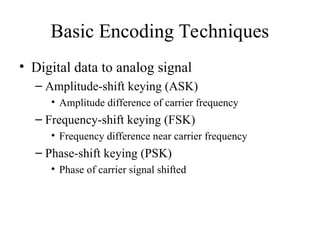
Basic Encoding Techniques
•Digital data to analog signal
– Amplitude-shift keying (ASK)
• Amplitude difference of carrier frequency
– Frequency-shift keying (FSK)
• Frequency difference near carrier frequency
– Phase-shift keying (PSK)
• Phase of carrier signal shifted
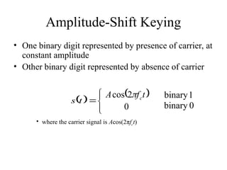
Amplitude-Shift Keying
• Onebinary digit represented by presence of carrier, at
constant amplitude
• Other binary digit represented by absence of carrier
• where the carrier signal is Acos(2πfct)
t
s
t
f
A c
2
cos
0
1
binary
0
binary
12.
Amplitude-Shift Keying
• Susceptibleto sudden gain changes
• Inefficient modulation technique
• On voice-grade lines, used up to 1200 bps
• Used to transmit digital data over optical fiber
13.
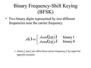
Binary Frequency-Shift Keying
(BFSK)
•Two binary digits represented by two different
frequencies near the carrier frequency
• where f1 and f2 are offset from carrier frequency fc by equal but
opposite amounts
t
s
t
f
A 1
2
cos
t
f
A 2
2
cos
1
binary
0
binary
14.
Binary Frequency-Shift Keying
(BFSK)
•Less susceptible to error than ASK
• On voice-grade lines, used up to 1200bps
• Used for high-frequency (3 to 30 MHz) radio
transmission
• Can be used at higher frequencies on LANs
that use coaxial cable
15.
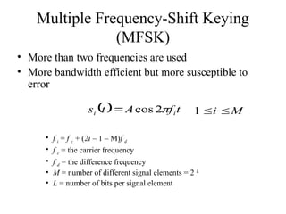
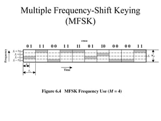
Multiple Frequency-Shift Keying
(MFSK)
•More than two frequencies are used
• More bandwidth efficient but more susceptible to
error
• f i = f c + (2i – 1 – M)f d
• f c = the carrier frequency
• f d = the difference frequency
• M = number of different signal elements = 2 L
• L = number of bits per signal element
t
f
A
t
s i
i
2
cos
M
i
1
16.
Multiple Frequency-Shift Keying
(MFSK)
•To match data rate of input bit stream, each
output signal element is held for:
Ts=LT seconds
• where T is the bit period (data rate = 1/T)
• So, one signal element encodes L bits
17.
Multiple Frequency-Shift Keying
(MFSK)
•Total bandwidth required
2Mfd
• Minimum frequency separation required
2fd=1/Ts
• Therefore, modulator requires a bandwidth of
Wd=2L
/LT=M/Ts
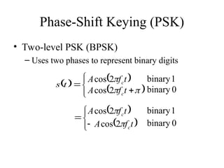
Phase-Shift Keying (PSK)
•Two-level PSK (BPSK)
– Uses two phases to represent binary digits
t
s
t
f
A c
2
cos
t
f
A c
2
cos
1
binary
0
binary
t
f
A c
2
cos
t
f
A c
2
cos
1
binary
0
binary
20.
Phase-Shift Keying (PSK)
•Differential PSK (DPSK)
– Phase shift with reference to previous bit
• Binary 0 – signal burst of same phase as previous signal
burst
• Binary 1 – signal burst of opposite phase to previous
signal burst
21.
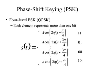
Phase-Shift Keying (PSK)
•Four-level PSK (QPSK)
– Each element represents more than one bit
t
s
4
2
cos
t
f
A c 11
4
3
2
cos
t
f
A c
4
3
2
cos
t
f
A c
4
2
cos
t
f
A c
01
00
10
22.
Phase-Shift Keying (PSK)
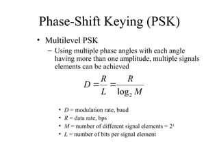
•Multilevel PSK
– Using multiple phase angles with each angle
having more than one amplitude, multiple signals
elements can be achieved
• D = modulation rate, baud
• R = data rate, bps
• M = number of different signal elements = 2L
• L = number of bits per signal element
M
R
L
R
D
2
log
23.
Performance
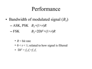
• Bandwidth ofmodulated signal (BT)
– ASK, PSK BT=(1+r)R
– FSK BT=2DF+(1+r)R
• R = bit rate
• 0 < r < 1; related to how signal is filtered
• DF = f2-fc=fc-f1
24.
Performance
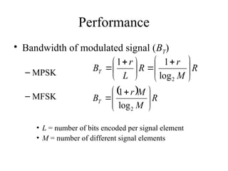
• Bandwidth ofmodulated signal (BT)
– MPSK
– MFSK
• L = number of bits encoded per signal element
• M = number of different signal elements
R
M
r
R
L
r
BT
2
log
1
1
R
M
M
r
BT
2
log
1
25.
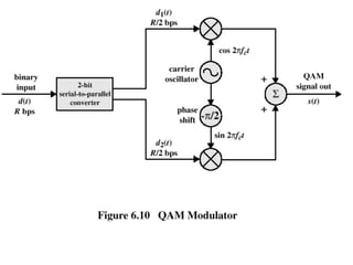
Quadrature Amplitude Modulation
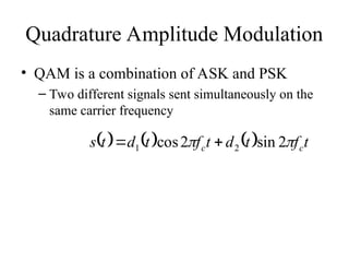
•QAM is a combination of ASK and PSK
– Two different signals sent simultaneously on the
same carrier frequency
t
f
t
d
t
f
t
d
t
s c
c
2
sin
2
cos 2
1
Reasons for AnalogModulation
• Modulation of digital signals
– When only analog transmission facilities are
available, digital to analog conversion required
• Modulation of analog signals
– A higher frequency may be needed for effective
transmission
– Modulation permits frequency division
multiplexing
28.
Basic Encoding Techniques
•Analog data to analog signal
– Amplitude modulation (AM)
– Angle modulation
• Frequency modulation (FM)
• Phase modulation (PM)
29.
Amplitude Modulation
t
f
t
x
n
t
s c
a
2
cos
1
• Amplitude Modulation
• cos2fct = carrier
• x(t) = input signal
• na = modulation index
– Ratio of amplitude of input signal to carrier
– a.k.a double sideband transmitted carrier
(DSBTC)
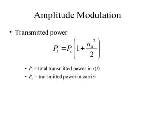
Amplitude Modulation
• Transmittedpower
• Pt = total transmitted power in s(t)
• Pc = transmitted power in carrier
2
1
2
a
c
t
n
P
P
32.
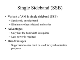
Single Sideband (SSB)
•Variant of AM is single sideband (SSB)
– Sends only one sideband
– Eliminates other sideband and carrier
• Advantages
– Only half the bandwidth is required
– Less power is required
• Disadvantages
– Suppressed carrier can’t be used for synchronization
purposes
33.
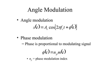
Angle Modulation
• Anglemodulation
• Phase modulation
– Phase is proportional to modulating signal
• np = phase modulation index
t
t
f
A
t
s c
c
2
cos
t
m
n
t p
34.
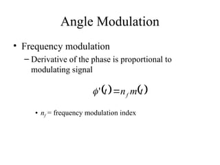
Angle Modulation
• Frequencymodulation
– Derivative of the phase is proportional to
modulating signal
• nf = frequency modulation index
t
m
n
t f
'
35.
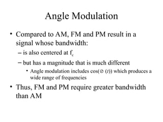
Angle Modulation
• Comparedto AM, FM and PM result in a
signal whose bandwidth:
– is also centered at fc
– but has a magnitude that is much different
• Angle modulation includes cos( (t)) which produces a
wide range of frequencies
• Thus, FM and PM require greater bandwidth
than AM
36.
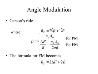
Angle Modulation
• Carson’srule
where
• The formula for FM becomes
B
BT 1
2
B
F
BT 2
2
FM
for
PM
for
2
B
A
n
B
F
A
n
m
f
m
p
37.
Basic Encoding Techniques
•Analog data to digital signal
– Pulse code modulation (PCM)
– Delta modulation (DM)
38.
Analog Data toDigital Signal
• Once analog data have been converted to
digital signals, the digital data:
– can be transmitted using NRZ-L
– can be encoded as a digital signal using a code
other than NRZ-L
– can be converted to an analog signal, using
previously discussed techniques
39.
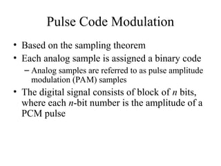
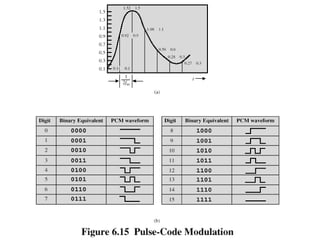
Pulse Code Modulation
•Based on the sampling theorem
• Each analog sample is assigned a binary code
– Analog samples are referred to as pulse amplitude
modulation (PAM) samples
• The digital signal consists of block of n bits,
where each n-bit number is the amplitude of a
PCM pulse
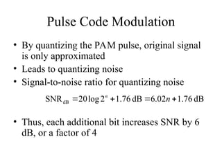
Pulse Code Modulation
•By quantizing the PAM pulse, original signal
is only approximated
• Leads to quantizing noise
• Signal-to-noise ratio for quantizing noise
• Thus, each additional bit increases SNR by 6
dB, or a factor of 4
dB
76
.
1
02
.
6
dB
76
.
1
2
log
20
SNRdB
n
n
42.
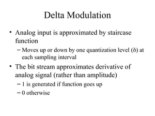
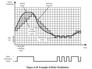
Delta Modulation
• Analoginput is approximated by staircase
function
– Moves up or down by one quantization level () at
each sampling interval
• The bit stream approximates derivative of
analog signal (rather than amplitude)
– 1 is generated if function goes up
– 0 otherwise
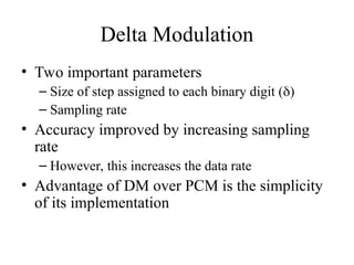
Delta Modulation
• Twoimportant parameters
– Size of step assigned to each binary digit ()
– Sampling rate
• Accuracy improved by increasing sampling
rate
– However, this increases the data rate
• Advantage of DM over PCM is the simplicity
of its implementation
45.
Reasons for Growthof Digital
Techniques
• Growth in popularity of digital techniques for
sending analog data
– Repeaters are used instead of amplifiers
• No additive noise
– TDM is used instead of FDM
• No intermodulation noise
– Conversion to digital signaling allows use of more
efficient digital switching techniques


![[DSC Europe 25] Josip Saban - Career building for data professionals.pptx](https://cdn.slidesharecdn.com/ss_thumbnails/zroflcttkm1vmli0txea-josip-saban-career-building-for-data-professionals-260123083019-587cdb8c-thumbnail.jpg?width=640&height=640&fit=bounds)
![[DSC Europe 25] Gordana Milutinovic Dumbelovic - From Insight to Oversight: A...](https://cdn.slidesharecdn.com/ss_thumbnails/t7dkjsfxqwwzceropjv4-gordana-milutinovicdumbelovic-from-insight-to-oversight-ai-driven-power-bi-moni-260119121559-9e0bf11b-thumbnail.jpg?width=640&height=640&fit=bounds)
![[DSC Europe 25] Bojan Djuricic - Predictive Design Process.pdf](https://cdn.slidesharecdn.com/ss_thumbnails/5awdrbedqdek3gqu2ezy-4-the-predictive-design-bojan-djuricic-260120105856-6c399e9b-thumbnail.jpg?width=640&height=640&fit=bounds)
![[DSC Europe 25] Harshvardhan Jain - From Pre-Trained to Purpose-Built: Fine-T...](https://cdn.slidesharecdn.com/ss_thumbnails/zru4zmiseku5tgvu2dgw-harshvardhan-jain-from-pre-trained-to-purpose-built-fine-tuning-llms-for-high-i-260119101520-8335585f-thumbnail.jpg?width=640&height=640&fit=bounds)


![[DSC Europe 25] Paula Garcia Esteban -Building the Future: The Role of Data S...](https://cdn.slidesharecdn.com/ss_thumbnails/9ld1r1bsqpwve8qfvphy-paula-garcia-esteban-building-the-future-260122103838-4171f5cb-thumbnail.jpg?width=640&height=640&fit=bounds)

![[DSC Europe 25] Milos Belcevic - Product Professional's Journey to Full-Stack...](https://cdn.slidesharecdn.com/ss_thumbnails/1zovd6fgsycdg4wvgvls-milos-belcevic-product-professionals-journey-to-full-stack-product-developer-260123083019-d993120d-thumbnail.jpg?width=640&height=640&fit=bounds)
![[DSC Europe 25] Dubravko Culibrk - Deep Learning for Mammography.pptx](https://cdn.slidesharecdn.com/ss_thumbnails/yiscimuktacgqoiu4dkp-deep-learning-for-mammography-260119121559-aad59182-thumbnail.jpg?width=640&height=640&fit=bounds)
