Downloaded 455 times


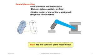
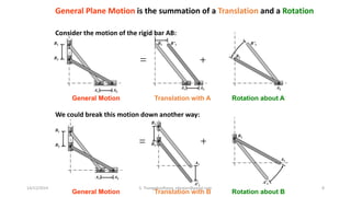
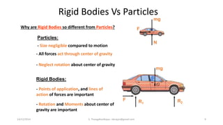
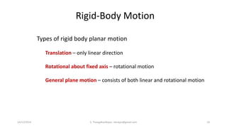


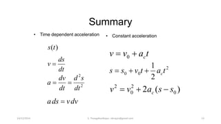


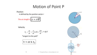
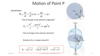
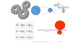


The document presents an overview of rigid body dynamics, focusing on various types of motion including translation, rotation, and general plane motion. It discusses the principles of motion in rigid bodies, differentiating them from particle motion, and includes relevant equations for angular velocity and acceleration. Additionally, it provides example problems related to angular motion and mechanisms such as the slider crank mechanism.


![Attack surfaces and attack tress[inform]](https://cdn.slidesharecdn.com/ss_thumbnails/lecture03-260108015941-a4dee53b-thumbnail.jpg?width=640&height=640&fit=bounds)


