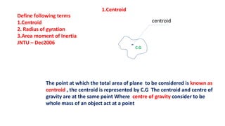
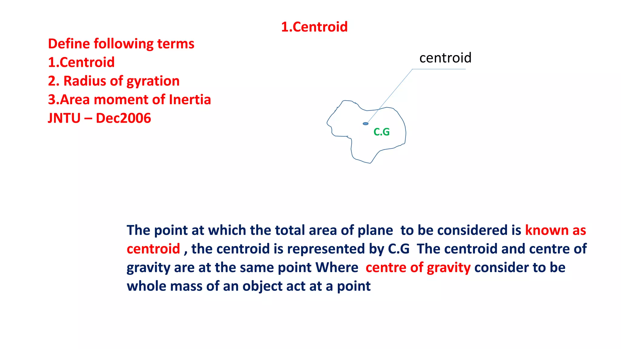
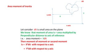
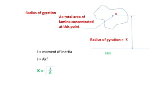
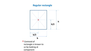
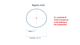
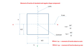
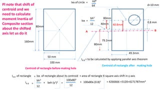
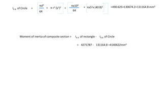
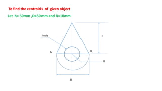
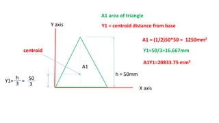
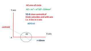
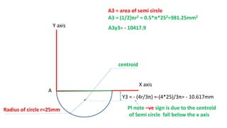
The document defines several terms:
1. Centroid - The point at which the total area of a plane is concentrated. It is where the average position of the total weight of the plane would balance.
2. Radius of gyration - The distance from the axis of rotation to the centroid. It is calculated as the square root of the moment of inertia divided by the total area.
3. Area moment of inertia - The product of the plane area and the square of the perpendicular distance to the axis of reference. It is a measure of the resistance offered by a plane figure to bending or twisting about an axis.
Torsion or twisting is a common concept in mechanical engineering systems. This section looks at the basic theory associated with torsion and examines some typical examples by calculating the main parameters. Further examples include determination of the torque and power requirements of torsional systems.
Lecture slides on the calculation of the bending stress in case of unsymmetrical bending. The Mohr's circle is used to determine the principal second moments of area.
In engineering, deflection is the degree to which a structural element is displaced under a load. It may refer to an angle or a distance.
The deflection distance of a member under a load is directly related to the slope of the deflected shape of the member under that load, and can be calculated by integrating the function that mathematically describes the slope of the member under that load. Deflection can be calculated by standard formula (will only give the deflection of common beam configurations and load cases at discrete locations), or by methods such as virtual work, direct integration, Castigliano's method, Macaulay's method or the direct stiffness method, amongst others. The deflection of beam elements is usually calculated on the basis of the Euler–Bernoulli beam equation while that of a plate or shell element is calculated using plate or shell theory.
This document gives the class notes of Unit 6: Bending and shear Stresses in beams. Subject: Mechanics of materials.
Syllabus contest is as per VTU, Belagavi, India.
Notes Compiled By: Hareesha N Gowda, Assistant Professor, DSCE, Bengaluru-78.
single degree of freedom systems forced vibrations KESHAV
SDOF, Forced vibration
includes following content
Forced vibrations of longitudinal and torsional systems,
Frequency Response to harmonic excitation,
excitation due to rotating and reciprocating unbalance,
base excitation, magnification factor,
Force and Motion transmissibility,
Quality Factor.
Half power bandwidth method,
Critical speed of shaft having single rotor of undamped systems.
Bending Stresses are important in the design of beams from strength point of view. The present source gives an idea on theory and problems in bending stresses.
Prof. V. V. Nalawade, Notes CGMI with practice numericalVrushali Nalawade
Centre of gravity is a point where the whole weight of the body is assumed to act. i.e., it is a point where entire distribution of gravitational force is supposed to be concentrated
It is generally denoted “G” for all three dimensional rigid bodies.
e.g. Sphere, table , vehicle, dam, human etc
Centroid is a point where the whole area of a plane lamina is assumed to act.
It is a point where the entire length, area & volume is supposed to be concentrated.
It is a geometrical centre of a figure.
It is used for two dimensional figures.
e.g. rectangle, circle, triangle, semicircle
Centroid is a point where the whole area of a plane lamina is assumed to act.
It is a point where the entire length, area & volume is supposed to be concentrated.
It is a geometrical centre of a figure.
It is used for two dimensional figures.
e.g. rectangle, circle, triangle, semicircle
Centroid is a point where the whole area of a plane lamina is assumed to act.
It is a point where the entire length, area & volume is supposed to be concentrated.
It is a geometrical centre of a figure.
It is used for two dimensional figures.
e.g. rectangle, circle, triangle, semicircle
The process of finding area of some plane region is called Quadrature. In this chapter we shall find the area bounded by some simple plane curves with the help of definite integral. For solving
(i) The area bounded by a cartesian curve y = f(x), x-axis and ordinates x = a and x = b is given by,
the problems on quadrature easily, if possible first draw the rough sketch of the required area.
b
Area = y dx
a
b
= f(x) dx
a
In chapter function, we have seen graphs of some simple elementary curves. Here we introduce some essential steps for curve tracing which will enable us to determine the required area.
(i) Symmetry
The curve f(x, y) = 0 is symmetrical
about x-axis if all terms of y contain even powers.
about y-axis if all terms of x contain even
powers.
about the origin if f (– x, – y) = f (x, y).
Examples
based on
Area Bounded by A Curve
For example, y2 = 4ax is symmetrical about x-axis, and x2 = 4ay is symmetrical about y- axis and the curve y = x3 is symmetrical about the origin.
(ii) Origin
Ex.1 Find the area bounded by the curve y = x3, x-axis and ordinates x = 1 and x = 2.
2
Sol. Required Area = ydx
1
If the equation of the curve contains no constant
2
= x3 dx =
Lx4 O2 15
MN PQ=
Ans.
term then it passes through the origin.
For example x2 + y2 + 2ax = 0 passes through origin.
(iii) Points of intersection with the axes
If we get real values of x on putting y = 0 in the equation of the curve, then real values of x and y = 0 give those points where the curve cuts the x-axis. Similarly by putting x = 0, we can get the points of intersection of the curve and y-axis.
1 4 1 4
Ex.2 Find the area bounded by the curve y = sec2x,
x-axis and the line x = 4
/4
Sol. Required Area = ydx
x0
For example, the curve x2/a2 + y2 /b2 = 1 intersects the axes at points (± a, 0) and (0, ± b) .
(iv) Region
/4
= sec2
0
xdx = tan x /4 = 1 Ans.
Write the given equation as y = f(x) , and find minimum and maximum values of x which determine the region of the curve.
For example for the curve xy2 = a2 (a – x)
Ex.3 Find the area bounded by the curve y = mx, x-axis and ordinates x = 1 and x = 2
2
Sol. Required area = y dx .
1
y = a
a x
x
2
= mxdx =
LMmx2 2
Now y is real, if 0 < x a , so its region lies between the lines x = 0 and x = a.
1 MN2
= m ( 4 – 1) =
2
PQ1
FGH3 JKm Ans.
Ex.4 Find the area bounded by the curve y = x (1– x)2 and x-axis.
Sol. Clearly the given curve meets the x-axis at (0,0) and (1,0) and for x = 0 to 1, y is positive
Ex.7 Find the area bounded between the curve y2 = 2y – x and y-axis.
Sol. The area between the given curve x = 2y – y2 and y-axis will be as shown in diagram.
so required area- Y
= xb1 xg2 dx
0
1
= ex 2x2 x3 jdx
0
O (0,0) (1,0) X
Lx2
2x3
x4 O1
1 2 1 1
= M P=
– + =
MN2 3 4 PQ0
2 3 4 12
Ans.
Required Area =
e2y y2 jdy
(i
1. Define following terms
1.Centroid
2. Radius of gyration
3.Area moment of Inertia
JNTU – Dec2006
1.Centroid
centroid
The point at which the total area of plane to be considered is known as
centroid , the centroid is represented by C.G The centroid and centre of
gravity are at the same point Where centre of gravity consider to be
whole mass of an object act at a point
C.G
2. x axis
Y
y axis
X
Let consider dA is small area on the plane
We know that moment of area is = area multiplied by
Perpendicular distance to axis of reference
i.e. - area moment = XdA
Then moment of moment or second moment
is = X2dA with respect to x axis
Area moment of Inertia
dA
= Y2dA with respect to y axis
3. Area moment of Inertia
x axis
Y
y axis
centroid
C.G
X
Ixx = Moment of Inertia about x axis
Iyy = Moment of Inertia about y axis
𝑿 𝟐 dAIxx =
𝒀 𝟐 dAIyy =
The area moment about a point is
the product of the plane area and
the normal distance of the point
from the reference line area. If this
is multiplied by the perpendicular
distance is called second moment
of area Let consider dA is small area on the plane
4. Radius of gyration
K
A= total area of
lamina concentrated
at this point
A
Radius of gyration =
axis
I = Ak2
I = moment of inertia
K = I
A
5. Parallel axis Theorem
X X
h
X axis
A B
Plane
centroid
Moment of Inertia about AB axis IAB = IXX + Ah2
Area of plane
Moment Inertia about
centroid
Moment of Inertia about AB axis IAB = moment of Inertia
about centroid + area Multiplied by square
of distance between
centroid and
axis parallel to centroid
7. Radius = r
Diameter = D = 2r
O O = centroid of
circle is known to
us by looking at
the component
Regular circle
8. A hole on a rectangle
whose diameter = 10mm
80mm
160mm
120mm
100mm
Non Regular component of hole on a rectangle
Centroid of the component to be calculated
17. R= 2m
Consider semi circle by splitting the composite section and mark
the centroid with respect to axis drawn considering + and –
(positive and negative with respect to axis)
- 4r/3π = (4x2)/3π = - 0.849
Area = A1= π22 /2= 6.28 m2
X1= - 0.849
Y1= 2.0
Y1= 2.0
- Ve sign is with respect to axis
Centroid of semi circle
22. Moment of Inertia of standard and regular shape component
h/2
h
b/2
b
xx
y
y
X axis
y axis
Centroid
I xx =
bh3
12
I yy =
hb3
12
Where I xx = moment of Inertia about xx axis
Where I yy = moment of Inertia about yy axis
23. x
X axis
x
Y
Y
Y1
BA
Moment of Inertia of
rectangle about the axis AB
parallel to axis xx is equal
to
IAB= Ixx + A(Y1) 2
Where Ixx moment of Inertia about xx axis
A area of rectangle and Y1 is distance
between the axis AB and x axis Pl note that
AB axis is parallel to x axis
IAB =
bh3
12
+{( b X h) (Y1)2
b
h
}
24. XX
Y
Y
X axis
Y axis
d = Diameter of circle
Circle Ixx =
πd4
64
centroid
Circle Iyy =
πd4
64
Plolar moment of Inertia Izz = Ixx+Iyy =
πd4
64
+
πd4
64
=
πd4
32
25. centroid
Radius = rRadius = r
4r/3π
Radius = r
For semicircle note centroid distance
Moment of Inertia of semicircle
For circle moment of Inertia about this
axis is known that is πd4/64 and for semi
circle it is( πd4/64)X ½ = πd4/128 pl note
that we do not have moment f Inertia of
semi circle about centroid axis which is to
be calculated applying parallel axis
theorem
x x
BA
moment of Inertia
for semi circle it is
( πd4/64)X ½ = πd4/128
Now IAB= Ixx +(AY1)2
Y1 =
Ixx =0.0068598d4
Ixx =0.0068598d4
Where IAB= πd4/128
A=πr2 or πd4/4
Ixx = IAB - (AY1)2
Y1
4r/3πY1 =
26. Let us know the moment of inertia of Triangle
A
B
moment of inertia of
Triangle about this axis
or base of triangle
is=
b
Y1=h/3
Ixx= moment of Inertia
Of triangle about
Centroid of triangle is
moment of inertia of Triangle about centroid= Ixx =IAB-A(y1)2 =
h
A = area of triangle
IAB = moment of inertia triangle about centroid
bh3
12
bh3
36
bh3
36
Applying parallel axis theorem
27. A hole on a rectangle
whose diameter = 10mm
80mm
160mm
120mm
100mm
Non Regular component of hole on a rectangle
Centroid of the component to be calculated
31. A hole on a rectangle
whose diameter = 10mm
80mm
160mm
120mm
100mm
Non Regular component of hole on a rectangle
Centroid of the component to be calculated
35. 50 mm
80mm
49.3mm
79.2mm
Centroid of rectangle before making hole
Centroid of rectangle after making hole
Pl note that shift of
centroid and we
need to calculate
moment Inertia of
Composite section
about the shifted
axis let us do it
Ixx =
bh3
12
Ixx of circle = πd4
64 d=10 mm
0.8 mm
A B
IA B = to be calculated by applying parallel axis theorem
IA B of rectangle Ixx of rectangle about its centroid + area of rectangle X square axis shift in y axis
160mm
100 mm
=
IA B =
bh3
12
+ bxh (y1)2
=
100x803
12
+ 100x80x (0.8)2 = 4266666 +5120=4271787mm4
40.8mm
80mm
80mm
40mm
36. IA B of Circle =
πd4
64
+ π r2 (y1)2
=
πx104
64
+ πx52x (40.8)2 =490.625+130674.2=131164.8 mm4
Moment of Inertia of composite section = IA B of rectangle - IA B of Circle
4271787 -= 131164.8 =4140622mm4
37. To find the centroids of given object
Let h= 50mm ,D=50mm and R=10mm
h
D
R
A B
Hole
38. A1 = (1/2)50*50 = 1250mm2
Y1=50/3=16.667mm
A1Y1=20833.75 mm3
A1
Y1= =
h = 50mm
A1 area of triangle
centroid
Y1 = centroid distance from base
h
3
50
3
X axis
Y axis
39. r=10mm
A2
Y2=0 since centroid of
Circle coincides and with axis
i.e. it lies in x axis
A2 = πr2 = π*102= 314mm2
A2Y2=0
centroid
A2 area of circle
Y axis
X axis
A
40. X axis
Y axis
Y3 = - (4r/3π) =-(4*25)/3π= - 10.617mm
Pl note –ve sign is due to the centroid
of Semi circle fall below the x axis
centroid
Radius of circle r=25mm
A3y3= - 10417.9
A3 = (1/2)πr2 = 0.5*π*252=981.25mm2
A3 = area of semi circle
A
43. Finding moment of inertia of object about the axis AB
h=50
D=b=50mm
R=D/2=25mm
r=d/2= 10mm
A B
44. Moment of inertia of Triangle about AB=(1/12)bh3 =
h=50 mm
B
50 mm
A
1
12
50 x 503
=520833 mm4
Axis about which moment
of inertia
To be taken
45. r=d/2= 10mm
A B
Moment of inertia of circle about AB=(πd4)/64 =
π 204
64
Centroid
=7850mm4
Axis about which moment
of inertia
To be taken
46. Moment of inertia of semi circle about AB=(1/128)*(πD4) =
π 504
128
D=b=50mm
A B
Centroid
=153320mm4
Axis about which moment
of inertia
To be taken
47. Moment of inertia of object about AB =
Moment of inertia of Triangle about AB
+
Moment of inertia of semi circle about AB(
-
Moment of inertia of circle about AB{(πd4)/64}
1
12
50 x 503= +
π 504
128
-
π 204
64
=x 520833 + 153320 - 7850 = 666303mm4
h=50
D=b=50mm
R=D/2=25mm
r=d/2= 10mm
A B
π 504
128
(1/12)bh3
(
48. To find the moment of Inertia about centroids of given object
Let h= 50mm ,D=50mm and R=10mm
h
D
R
A B
Hole
50. Moment of inertia of object about AB =
Moment of inertia of Triangle about AB
+
Moment of inertia of semi circle about AB(
-
Moment of inertia of circle about AB{(πd4)/64}
1
12
50 x 503= +
π 504
128
-
π 204
64
=x 520833 + 153320 - 7850 = 666303mm4
h=50
D=b=50mm
R=D/2=25mm
r=d/2= 10mm
A B
π 504
128
(1/12)bh3
(
51. To find the moment of Inertia about centroid of given object
Let h= 50mm ,D=50mm and R=10mm
h
D
R
A B
Hole
5.4327mm
Centroid of composite section
Calculated
Moment of inertia of
object about AB = 666303mm4
moment of Inertia
about centroid is to be
calculated
52. Moment of Inertia about centroid calculation
IAB = IXX+ Ah2 Moment of Inertia about an axis= IAB= 666303mm4
Moment of Inertia about centroid to be calculated
A = Triangle area + semicircle area with radius 25mm – circle area with radius 10mm
h = distance between axis to centroid = 5.4327mm
1250= + 981.25 – 314 =1917.25mm2
IXX = IAB Ah2
= 1917.25 x666303 –
–
5.43272 = 610395.99mm4