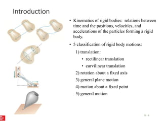
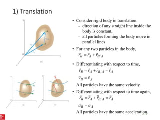
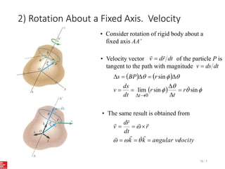
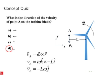
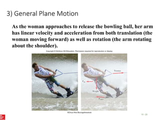
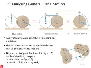
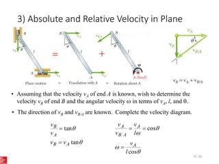
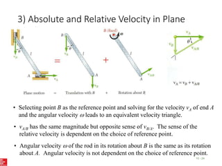
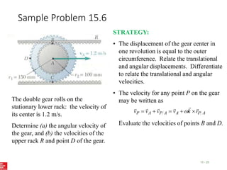
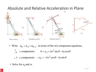
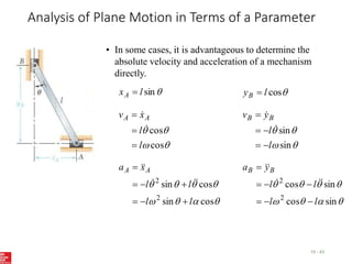
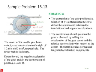
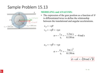
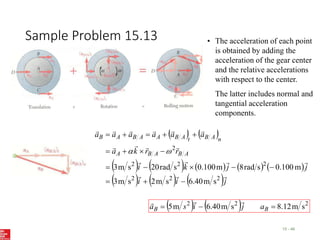
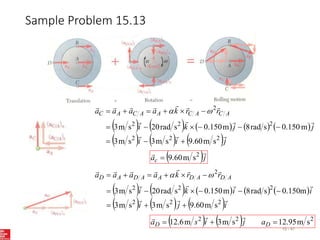
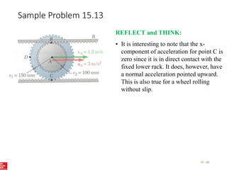
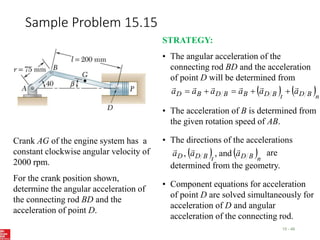
2. Contents
15 - 2
Introduction
Translation
Rotation About a Fixed Axis: Velocity
Rotation About a Fixed Axis: Acceleration
Rotation About a Fixed Axis:
Representative Slab
Equations Defining the Rotation of a Rigid
Body About a Fixed Axis
Sample Problem 15.3
Analyzing General Plane Motion
Absolute and Relative Velocity in Plane
Motion
Sample Problem 15.6
Sample Problem 15.7
Instantaneous Center of Rotation
Sample Problem 15.9
Sample Problem 15.10
Absolute and Relative Acceleration in Plane
Motion
Analysis of Plane Motion in Terms of a
Parameter
Sample Problem 15.13
Sample Problem 15.15
Sample Problem 15.16
Rate of Change With Respect to a Rotating
Frame
Plane Motion Relative to a Rotating Frame
Sample Problem 15.19
Sample Problem 15.20
Motion About a Fixed Point
General Motion
Sample Problem 15.21
Three Dimensional Motion Relative to a
Rotating Frame
Frame of Reference in General Motion
Sample Problem 15.25
3. Applications
15 - 3
The linkage between train wheels is an example of curvilinear
translation – the link stays horizontal as it swings through its
motion.
4. Applications
15 - 4
Planetary gear systems are used to get high reduction ratios
with minimum weight and space. How can we design the
correct gear ratios?
5. Introduction
15 - 5
• Kinematics of rigid bodies: relations between
time and the positions, velocities, and
accelerations of the particles forming a rigid
body.
• 5 classification of rigid body motions:
5) general motion
4) motion about a fixed point
3) general plane motion
2) rotation about a fixed axis
• curvilinear translation
• rectilinear translation
1) translation:
6. 1) Translation
15 - 6
• Consider rigid body in translation:
- direction of any straight line inside the
body is constant,
- all particles forming the body move in
parallel lines.
• For any two particles in the body,
A
B
A
B r
r
r
• Differentiating with respect to time,
A
B
A
A
B
A
B
v
v
r
r
r
r
All particles have the same velocity.
A
B
A
A
B
A
B
a
a
r
r
r
r
• Differentiating with respect to time again,
All particles have the same acceleration.
7. 2) Rotation About a Fixed Axis. Velocity
15 - 7
• Consider rotation of rigid body about a
fixed axis AA’
• Velocity vector of the particle P is
tangent to the path with magnitude
dt
r
d
v
dt
ds
v
sin
sin
lim
sin
0
r
t
r
dt
ds
v
r
BP
s
t
locity
angular ve
k
k
r
dt
r
d
v
• The same result is obtained from
8. Concept Quiz
15 - 8
What is the direction of the velocity
of point A on the turbine blade?
A
a) →
b) ←
c) ↑
d) ↓
A
v r
x
y
ˆ ˆ
A
v k Li
ˆ
A
v L j
L
9. 2) Rotation About a Fixed Axis. Acceleration
15 - 9
• Differentiating to determine the acceleration,
v
r
dt
d
dt
r
d
r
dt
d
r
dt
d
dt
v
d
a
•
k
k
k
celeration
angular ac
dt
d
component
on
accelerati
radial
component
on
accelerati
l
tangentia
r
r
r
r
a
• Acceleration of P is combination of two
vectors,
10. 2) Rotation About a Fixed Axis. Representative Slab
15 - 10
• Consider the motion of a representative slab in
a plane perpendicular to the axis of rotation.
• Velocity of any point P of the slab,
r
v
r
k
r
v
• Acceleration of any point P of the slab,
r
r
k
r
r
a
2
• Resolving the acceleration into tangential and
normal components,
2
2
r
a
r
a
r
a
r
k
a
n
n
t
t
11. Concept Quiz
15 - 11
What is the direction of the normal
acceleration of point A on the turbine
blade?
a) →
b) ←
c) ↑
d) ↓
2
n
a r
x
y
2 ˆ
( )
n
a Li
2ˆ
n
a L i
A
L
12. Equations Defining the Rotation of a Rigid Body About a Fixed Axis
15 - 12
• Motion of a rigid body rotating around a fixed axis is
often specified by the type of angular acceleration.
d
d
dt
d
dt
d
d
dt
dt
d
2
2
or
• Recall
• Uniform Rotation, = 0:
t
0
• Uniformly Accelerated Rotation, = constant:
0
2
0
2
2
2
1
0
0
0
2
t
t
t
13. Sample Problem 15.3
15 - 13
Cable C has a constant acceleration of
225 mm/s2 and an initial velocity of
300 mm/s, both directed to the right.
Determine (a) the number of revolutions
of the pulley in 2 s, (b) the velocity and
change in position of the load B after 2 s,
and (c) the acceleration of the point D on
the rim of the inner pulley at t = 0.
STRATEGY:
• Due to the action of the cable, the
tangential velocity and acceleration of
D are equal to the velocity and
acceleration of C. Calculate the initial
angular velocity and acceleration.
• Apply the relations for uniformly
accelerated rotation to determine the
velocity and angular position of the
pulley after 2 s.
• Evaluate the initial tangential and
normal acceleration components of D.
14. Sample Problem 15.3
15 - 14
MODELING and ANALYSIS:
• The tangential velocity and acceleration of D are equal to the
velocity and acceleration of C.
• Apply the relations for uniformly accelerated rotation to
determine velocity and angular position of pulley after 2 s.
rad
14
s
2
s
rad
3
s
2
s
rad
4 2
2
2
1
2
2
1
0
t
t
revs
of
number
rad
2
rev
1
rad
14
N rev
23
.
2
N
15. Sample Problem 15.3
15 - 15
• Evaluate the initial tangential and normal acceleration
components of D.
Magnitude and direction of the total acceleration,
( ) ( )
( ) ( )
2 2
2 2 2
225 1200 1221mm s
D D D
t n
a a a
= +
= + = 2
1.221m s
=
D
a
4
.
79
16. Sample Problem 15.3
15 - 16
REFLECT and THINK:
• A double pulley acts similarly to a system of
gears; for every 75 mm that point C moves to
the right, point B moves 125 mm upward.
This is also similar to the rear tire of your
bicycle. As you apply tension to the chain, the
rear sprocket rotates a small amount, causing
the rear wheel to rotate through a much larger
angle.
17. Group Problem Solving
15 - 17
A series of small machine components
being moved by a conveyor belt pass over
a 120 mm-radius idler pulley. At the instant
shown, the velocity of point A is
300 mm/s to the left and its acceleration is
180 mm/s2 to the right. Determine (a) the
angular velocity and angular acceleration
of the idler pulley, (b) the total acceleration
of the machine
component at B.
STRATEGY:
• Using the linear velocity and
accelerations, calculate the angular
velocity and acceleration.
• Using the angular velocity,
determine the normal acceleration.
• Determine the total acceleration
using the tangential and normal
acceleration components of B.
18. Group Problem Solving
15 - 18
v= 300 mm/s at= 180 mm/s2
Find the angular velocity of the idler
pulley using the linear velocity at B.
300 mm/s (120 mm)
v r
2.50 rad/s
2
180 mm/s (120 mm)
a r
2
1.500 rad/s
B
Find the angular velocity of the idler
pulley using the linear velocity at B.
Find the normal acceleration of point B.
2
2
(120 mm)(2.5 rad/s)
n
a r
2
750 mm/s
n
a
What is the direction of
the normal acceleration
of point B?
Downwards, towards
the center
MODELING and ANALYSIS:
19. Group Problem Solving
15 - 19
an= 750 mm/s2
Find the total acceleration of the
machine component at point B.
at= 180 mm/s2
2
750 mm/s
n
a
2
771 mm/s
B
a 76.5
at= 180 mm/s2
an= 750 mm/s2
B
a
2
180 mm/s
t
a
B
2 2 2
180 750 771.3 mm/s
a
Calculate the magnitude
Calculate the angle from
the horizontal
o
750
arctan 76.5
180
Combine for a final answer
20. 3) General Plane Motion
15 - 20
As the woman approaches to release the bowling ball, her arm
has linear velocity and acceleration from both translation (the
woman moving forward) as well as rotation (the arm rotating
about the shoulder).
21. 3) Analyzing General Plane Motion
15 - 21
• General plane motion is neither a translation nor
a rotation.
• General plane motion can be considered as the
sum of a translation and rotation.
• Displacement of particles A and B to A2 and B2
can be divided into two parts:
- translation to A2 and
- rotation of about A2 to B2
1
B
1
B
22. 3) Absolute and Relative Velocity in Plane Motion
15 - 22
• Any plane motion can be replaced by a translation of an
arbitrary reference point A and a simultaneous rotation
about A.
A
B
A
B v
v
v
r
v
r
k
v A
B
A
B
A
B
A
B
A
B r
k
v
v
23. 3) Absolute and Relative Velocity in Plane
Motion
15 - 23
• Assuming that the velocity vA of end A is known, wish to determine the
velocity vB of end B and the angular velocity in terms of vA, l, and .
• The direction of vB and vB/A are known. Complete the velocity diagram.
tan
tan
A
B
A
B
v
v
v
v
cos
cos
l
v
l
v
v
v
A
A
A
B
A
24. 3) Absolute and Relative Velocity in Plane
Motion
15 - 24
• Selecting point B as the reference point and solving for the velocity vA of end A
and the angular velocity leads to an equivalent velocity triangle.
• vA/B has the same magnitude but opposite sense of vB/A. The sense of the
relative velocity is dependent on the choice of reference point.
• Angular velocity of the rod in its rotation about B is the same as its rotation
about A. Angular velocity is not dependent on the choice of reference point.
25. Sample Problem 15.6
15 - 25
The double gear rolls on the
stationary lower rack: the velocity of
its center is 1.2 m/s.
Determine (a) the angular velocity of
the gear, and (b) the velocities of the
upper rack R and point D of the gear.
STRATEGY:
• The displacement of the gear center in
one revolution is equal to the outer
circumference. Relate the translational
and angular displacements. Differentiate
to relate the translational and angular
velocities.
• The velocity for any point P on the gear
may be written as
Evaluate the velocities of points B and D.
A
P
A
A
P
A
P r
k
v
v
v
v
26. Sample Problem 15.6
15 - 26
x
y
MODELING and ANALYSIS
• The displacement of the gear center in one revolution is
equal to the outer circumference.
For xA > 0 (moves to right), < 0 (rotates clockwise).
1
2
2
r
x
r
x
A
A
Differentiate to relate the translational and angular
velocities.
m
0.150
s
m
2
.
1
1
1
r
v
r
v
A
A
k
k
s
rad
8
27. Sample Problem 15.6
15 - 27
• For any point P on the gear, A
P
A
A
P
A
P r
k
v
v
v
v
Velocity of the upper rack is equal to
velocity of point B:
i
i
j
k
i
r
k
v
v
v A
B
A
B
R
s
m
8
.
0
s
m
2
.
1
m
10
.
0
s
rad
8
s
m
2
.
1
i
vR
s
m
2
Velocity of the point D:
i
k
i
r
k
v
v A
D
A
D
m
150
.
0
s
rad
8
s
m
2
.
1
s
m
697
.
1
s
m
2
.
1
s
m
2
.
1
D
D
v
j
i
v
28. Sample Problem 15.6
15 - 28
REFLECT and THINK:
• Note that point A was free to translate,
and Point C, since it is in contact with
the fixed lower rack, has a velocity of
zero. Every point along diameter CAB
has a velocity vector directed to the right
and the magnitude of the velocity
increases linearly as the distance from
point C increases.
29. Sample Problem 15.7
15 - 29
The crank AB has a constant clockwise
angular velocity of 2000 rpm.
For the crank position indicated,
determine (a) the angular velocity of
the connecting rod BD, and (b) the
velocity of the piston P.
STRATEGY:
• Will determine the absolute velocity of
point D with
B
D
B
D v
v
v
• The velocity is obtained from the
given crank rotation data.
B
v
• The directions of the absolute velocity
and the relative velocity are
determined from the problem geometry.
D
v
B
D
v
• The unknowns in the vector expression
are the velocity magnitudes
which may be determined from the
corresponding vector triangle.
B
D
D v
v and
• The angular velocity of the connecting
rod is calculated from .
B
D
v
30. Sample Problem 15.7
15 - 30
MODELING and ANALYSIS:
• Will determine the absolute velocity of point D with
B
D
B
D v
v
v
• The velocity is obtained from the crank rotation data.
B
v
( ) ( )( )
rev min 2 rad
2000 209.4 rad s
min 60s rev
75mm 209.4 rad s 15,705mm s
æ ö
æ ö æ ö
= =
ç ÷ ç ÷
ç ÷
è ø è ø
è ø
= = =
AB
B AB
v AB
p
w
w
The velocity direction is as shown.
• The direction of the absolute velocity is horizontal.
The direction of the relative velocity is
perpendicular to BD. Compute the angle between the
horizontal and the connecting rod from the law of sines.
D
v
B
D
v
sin40 sin
13.95
200mm 75mm
°
= = °
b
b
31. Sample Problem 15.7
15 - 31
• Determine the velocity magnitudes
from the vector triangle.
B
D
D v
v and
B
D
B
D v
v
v
15,705mm s
sin53.95 sin50 sin76.05
= =
° ° °
D B
D
v
v
13,083mm s 13.08m s
12,400mm s 12.4m s
= =
= =
D
D B
v
v
13.08m s
= =
P D
v v
k
BD
s
rad
0
.
62
32. Sample Problem 15.7
15 - 32
REFLECT and THINK:
Note that as the crank continues to move
clockwise below the center line, the piston
changes direction and starts to move to the
left.
Can you see what happens to the motion of
the connecting rod at that point?
33. Instantaneous Center of Rotation
15 - 33
• Plane motion of all particles in a slab can always be
replaced by the translation of an arbitrary point A and a
rotation about A with an angular velocity that is
independent of the choice of A.
• The same translational and rotational velocities at A are
obtained by allowing the slab to rotate with the same
angular velocity about the point C on a perpendicular to
the velocity at A.
• The velocity of all other particles in the slab are the same
as originally defined since the angular velocity and
translational velocity at A are equivalent.
• As far as the velocities are concerned, the slab seems to
rotate about the instantaneous center of rotation C.
34. Instantaneous Center of Rotation
15 - 34
• If the velocity at two points A and B are known, the
instantaneous center of rotation lies at the intersection
of the perpendiculars to the velocity vectors through A
and B .
• If the velocity vectors at A and B are perpendicular to
the line AB, the instantaneous center of rotation lies at
the intersection of the line AB with the line joining the
extremities of the velocity vectors at A and B.
• If the velocity vectors are parallel, the instantaneous
center of rotation is at infinity and the angular velocity
is zero.
• If the velocity magnitudes are equal, the instantaneous
center of rotation is at infinity and the angular velocity
is zero.
35. Instantaneous Center of Rotation
15 - 35
• The instantaneous center of rotation lies at the intersection of
the perpendiculars to the velocity vectors through A and B .
cos
l
v
AC
v A
A
tan
cos
sin
A
A
B
v
l
v
l
BC
v
• The velocities of all particles on the rod are as if they were
rotated about C.
• The particle at the center of rotation has zero velocity.
• The particle coinciding with the center of rotation changes
with time and the acceleration of the particle at the
instantaneous center of rotation is not zero.
• The acceleration of the particles in the slab cannot be
determined as if the slab were simply rotating about C.
• The trace of the locus of the center of rotation on the body
is the body centrode and in space is the space centrode.
36. Instantaneous Center of Rotation
15 - 36
At the instant shown, what is the
approximate direction of the velocity
of point G, the center of bar AB?
a)
b)
c)
d)
G
37. Sample Problem 15.9
15 - 37
The double gear rolls on the
stationary lower rack: the velocity
of its center is 1.2 m/s.
Determine (a) the angular velocity
of the gear, and (b) the velocities of
the upper rack R and point D of the
gear.
STRATEGY:
• The point C is in contact with the stationary
lower rack and, instantaneously, has zero
velocity. It must be the location of the
instantaneous center of rotation.
• Determine the angular velocity about C
based on the given velocity at A.
• Evaluate the velocities at B and D based on
their rotation about C.
38. Sample Problem 15.9
15 - 38
MODELING and ANALYSIS:
• The point C is in contact with the stationary lower rack
and, instantaneously, has zero velocity. It must be the
location of the instantaneous center of rotation.
• Determine the angular velocity about C based on the
given velocity at A.
s
rad
8
m
0.15
s
m
2
.
1
A
A
A
A
r
v
r
v
• Evaluate the velocities at B and D based on their rotation
about C.
s
rad
8
m
25
.
0
B
B
R r
v
v
i
vR
s
m
2
s
rad
8
m
2121
.
0
m
2121
.
0
2
m
15
.
0
D
D
D
r
v
r
s
m
2
.
1
2
.
1
s
m
697
.
1
j
i
v
v
D
D
REFLECT and THINK:
The results are the same as in
Sample Prob. 15.6, as
you would expect, but it took
much less computation to get
them.
39. Absolute and Relative Acceleration in Plane Motion
15 - 39
As the HPV bicycle accelerates, a point on the top of the
wheel will have acceleration due to the acceleration from the
axle (the overall linear acceleration of the bike), the
tangential acceleration of the wheel from the angular
acceleration, and the normal acceleration due to the angular
velocity.
40. Absolute and Relative Acceleration in Plane
Motion
15 - 40
• Absolute acceleration of a particle of the slab,
A
B
A
B a
a
a
• Relative acceleration associated with rotation about A includes
tangential and normal components,
A
B
a
A
B
n
A
B
A
B
t
A
B
r
a
r
k
a
2
2
r
a
r
a
n
A
B
t
A
B
41. Absolute and Relative Acceleration in Plane
Motion
15 - 41
• Given
determine
,
and A
A v
a
.
and
B
a
t
A
B
n
A
B
A
A
B
A
B
a
a
a
a
a
a
• Vector result depends on sense of and the
relative magnitudes of n
A
B
A a
a and
A
a
• Must also know angular velocity .
42. Absolute and Relative Acceleration in Plane
Motion
15 - 42
x components:
cos
sin
0 2
l
l
aA
y components:
sin
cos
2
l
l
aB
• Solve for aB and .
• Write in terms of the two component equations,
A
B
A
B a
a
a
43. Analysis of Plane Motion in Terms of a Parameter
15 - 43
• In some cases, it is advantageous to determine the
absolute velocity and acceleration of a mechanism
directly.
sin
l
xA
cos
l
yB
cos
cos
l
l
x
v A
A
sin
sin
l
l
y
v B
B
cos
sin
cos
sin
2
2
l
l
l
l
x
a A
A
sin
cos
sin
cos
2
2
l
l
l
l
y
a B
B
44. Sample Problem 15.13
15 - 44
The center of the double gear has a
velocity and acceleration to the right of
1.2 m/s and 3 m/s2, respectively. The
lower rack is stationary.
Determine (a) the angular acceleration
of the gear, and (b) the acceleration of
points B, C, and D.
STRATEGY:
• The expression of the gear position as a
function of is differentiated twice to
define the relationship between the
translational and angular accelerations.
• The acceleration of each point on the
gear is obtained by adding the
acceleration of the gear center and the
relative accelerations with respect to the
center. The latter includes normal and
tangential acceleration components.
45. Sample Problem 15.13
15 - 45
MODELING and ANALYSIS:
• The expression of the gear position as a function of
is differentiated twice to define the relationship
between the translational and angular accelerations.
1
1
1
r
r
v
r
x
A
A
s
rad
8
m
0.150
s
m
2
.
1
1
r
vA
1
1 r
r
aA
m
150
.
0
s
m
3 2
1
r
aA
k
k
2
s
rad
20
46. Sample Problem 15.13
15 - 46
j
i
i
j
j
k
i
r
r
k
a
a
a
a
a
a
a
A
B
A
B
A
n
A
B
t
A
B
A
A
B
A
B
2
2
2
2
2
2
2
s
m
40
.
6
s
m
2
s
m
3
m
100
.
0
s
rad
8
m
100
.
0
s
rad
20
s
m
3
2
2
2
s
m
12
.
8
s
m
40
.
6
m
5
B
B a
j
i
s
a
• The acceleration of each point
is obtained by adding the
acceleration of the gear center
and the relative accelerations
with respect to the center.
The latter includes normal and
tangential acceleration
components.
47. Sample Problem 15.13
15 - 47
j
i
i
j
j
k
i
r
r
k
a
a
a
a A
C
A
C
A
A
C
A
C
2
2
2
2
2
2
2
s
m
60
.
9
s
m
3
s
m
3
m
150
.
0
s
rad
8
m
150
.
0
s
rad
20
s
m
3
j
ac
2
s
m
60
.
9
i
j
i
i
i
k
i
r
r
k
a
a
a
a A
D
A
D
A
A
D
A
D
2
2
2
2
2
2
2
s
m
60
.
9
s
m
3
s
m
3
m
150
.
0
s
rad
8
m
150
.
0
s
rad
20
s
m
3
2
2
2
s
m
95
.
12
s
m
3
m
6
.
12
D
D a
j
i
s
a
48. Sample Problem 15.13
15 - 48
REFLECT and THINK:
• It is interesting to note that the x-
component of acceleration for point C is
zero since it is in direct contact with the
fixed lower rack. It does, however, have
a normal acceleration pointed upward.
This is also true for a wheel rolling
without slip.
49. Sample Problem 15.15
15 - 49
Crank AG of the engine system has a
constant clockwise angular velocity of
2000 rpm.
For the crank position shown,
determine the angular acceleration of
the connecting rod BD and the
acceleration of point D.
STRATEGY:
• The angular acceleration of the
connecting rod BD and the acceleration
of point D will be determined from
n
B
D
t
B
D
B
B
D
B
D a
a
a
a
a
a
• The acceleration of B is determined from
the given rotation speed of AB.
• The directions of the accelerations
are
determined from the geometry.
n
B
D
t
B
D
D a
a
a
and
,
,
• Component equations for acceleration
of point D are solved simultaneously for
acceleration of D and angular
acceleration of the connecting rod.
50. Sample Problem 15.15
15 - 50
• The acceleration of B is determined from the given rotation
speed of AB.
MODELING and ANALYSIS:
• The angular acceleration of the connecting rod BD and
the acceleration of point D will be determined from
n
B
D
t
B
D
B
B
D
B
D a
a
a
a
a
a
51. Sample Problem 15.15
15 - 51
• The directions of the accelerations are
determined from the geometry.
n
B
D
t
B
D
D a
a
a
and
,
,
From Sample Problem 15.3, BD = 62.0 rad/s, b = 13.95o.
The direction of (aD/B)t is known but the sense is not known,
i
a
a D
D
52. Sample Problem 15.15
15 - 52
n
B
D
t
B
D
B
B
D
B
D a
a
a
a
a
a
• Component equations for acceleration of point D are solved
simultaneously.
x components:
y components:
53. Sample Problem 15.15
15 - 53
REFLECT and THINK:
• In this solution, you looked at the
magnitude and direction of each term
(𝑎𝐵 and 𝑎𝐷 𝐵 ) and then found the x and
y components.
• Alternatively, you could have assumed
that 𝑎𝐷 was to the left, 𝛼𝐵𝐷 was
positive, and then substituted in the
vector quantities to get:
𝑎𝐷 = 𝑎𝐵 + 𝛼𝑘 × 𝑟𝐷 𝐵 − 𝜔2𝑟𝐷 𝐵
• These produce These identical
expressions for the i and j components
compared to the previous equations if
you substitute in the numbers.
54. 4) Motion About a Fixed Point
15 - 54
• The most general displacement of a rigid body with a
fixed point O is equivalent to a rotation of the body
about an axis through O.
• With the instantaneous axis of rotation and angular
velocity the velocity of a particle P of the body is
,
r
dt
r
d
v
and the acceleration of the particle P is
.
dt
d
r
r
a
• Angular velocities have magnitude and direction and
obey parallelogram law of addition. They are vectors.
• As the vector moves within the body and in space,
it generates a body cone and space cone which are
tangent along the instantaneous axis of rotation.
• The angular acceleration represents the velocity of
the tip of .
55. 5) General Motion
15 - 55
• For particles A and B of a rigid body,
A
B
A
B v
v
v
• Particle A is fixed within the body and motion of
the body relative to AX’Y’Z’ is the motion of a
body with a fixed point
A
B
A
B r
v
v
• Similarly, the acceleration of the particle P is
A
B
A
B
A
A
B
A
B
r
r
a
a
a
a
• Most general motion of a rigid body is equivalent to:
- a translation in which all particles have the same
velocity and acceleration of a reference particle A, and
- of a motion in which particle A is assumed fixed.
Suggestions: First explain the direction of tangential velocity from a conceptual standpoint, then show the cross product. Can also discuss the velocity of other points on the blade. Ask students to set up the cross product, get the –j or downward direction.