Download as PDF, PPTX

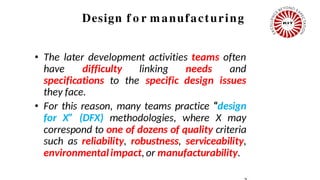
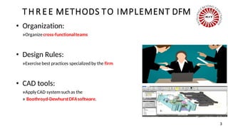

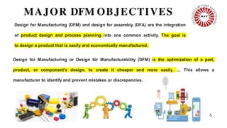


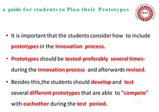


1. The document discusses various aspects of designing products for manufacturing including design for manufacturing (DFM) and design for assembly (DFA). It outlines three methods to implement DFM: organizing cross-functional teams, using design rules, and applying CAD tools. 2. Major objectives of DFM include reducing component costs, assembly costs, and production support costs. Methods to reduce costs include standardizing parts, choosing appropriate production scales, and integrating parts. 3. Prototyping principles outlined in the document are that analytical prototypes are more flexible than physical ones, physical prototypes are needed to detect unanticipated issues, and prototypes can reduce risks and expedite the development process.


![AGRICULTURAL WASTE MANAGEMENT Unit 1 introduction [autosaved]](https://cdn.slidesharecdn.com/ss_thumbnails/unit1introductionautosaved-210916033213-thumbnail.jpg?width=640&height=640&fit=bounds)


