The document discusses design for manufacturing and assembly (DFMA). It describes how Boothroyd and Dewhurst pioneered work on DFMA in the 1970s by analyzing existing product designs and developing guidelines to improve designs based on manufacturing and assembly ease. Their methods evaluate assembly efficiency and identify opportunities to reduce part count, simplify assembly operations, and make designs more amenable to different assembly methods like manual, robotic, or high-speed automated assembly. The document provides examples of applying DFMA principles and guidelines to redesign products for improved assembly efficiency.
DESIGN FOR MANUFACTURING AND ASSEMBLY.A really good insight of DFA and DFM. Also includes a very precise and appealing caste study on aimplemention of DFMA on a motor drive assembly.
Engineering Design is an iterative decision-making process used to devise a component, product, process, or system to meet the needs and functions desired by the user in a sustainable manner.
This report is a research on how to use DFM (Design For Manufacturing) engineering method to reduce the cost and time of manufacturing. Additionally it is describing (how to choose/which is the best) production(manufacturing) technology.
This project deals with the modeling of cooler tank parametric model as per the client requirement. Finding the best manufacturing process preparing mould base for the same, analyzing different manufacturing process by doing CNC program by changing milling parameters (feed, speed, cutters….).So that optimum parameters for manufacturing will be suggested which is useful to reduce the costs and efforts. Plastic flow analysis will be conducted to check the material flow and filling. So that reduction in the pre-machining cost will be done by rectifying the problem. FEM Based analysis will be conducted on mould structure to reduce weight of the mould. And thermal analysis will be conducted to suggest optimized cooling channel design. Modeling, mould base preparation, manufacturing, cnc programming will be done
In machining fixtures, minimizing workpiece deformation due to clamping and cutting forces is essential
to maintain the machining accuracy. The various methodology used for clamping operation used in different application
by various authors are reviewed in this paper. Fixture is required in various industries according to their application. This can be
achieved by selecting the optimal location of fixturing elements such as locators and clamps. The fixture set up for component is done
manually. For that more cycle time required for loading and unloading the material. So, there is need to develop system which can
help in improving productivity and time. Fixtures reduce operation time and increases productivity and high quality of operation is
possible.
Demystifying Designing for ‘X’ by ProTek Medical ProtekMedical
http://www.protek.ie/
Annette Carty-Mole B.Eng (Hons)
Design Engineer, ProTek Medical
When a company is given the task of designing a
new product or redesigning an existing product, it
is important to keep in mind the three main goals
of cost, quality and speed. These goals can be
further split into more quantitative criteria which
are relevant throughout the product’s life cycle.
Designing for manufacture and assembly are typical
examples of two criteria which will have a large
impact on the cost, quality and speed at which the
product is developed. The methodology of design
that meets an all-encompassing range of criteria is
known as designing for ‘X’.
A Review on Design of a Fixture for Rear Coverijsrd.com
In fixtures which are used for machining process, minimizing work piece deformation due to clamping and cutting forces is necessary due to which machining accuracy can be maintained. The different methodologies used for clamping operation in different application by various authors are discussed in this paper. Fixtures are required in different industries according to specific application. Rear Cover is important part in agriculture tractor. The fixture set up for Rear Cover is done manually, which leads to machining defects, poor quality, increase in rejection rate, more cycle time and more hectic to operator. So, there is need to develop system which can help in achieve quality, increase productivity, elimination of human error, reduction in cycle time.
Engineering Design is a decision making process (often iterative or recursive) in which the sciences are applied to modify/create something to meet predefined objectives (specifications). Basic stages of the design process include establishment of objectives and criteria, analysis, synthesis, definition of actual manufacturing techniques and routes as well as the modes of usage, maintenance and disposal.
Design and Engineering Module 3: Prototype to ProductNaseel Ibnu Azeez
As per KTU Syllabus Design and Engineering
Prototyping- rapid prototyping; testing and evaluation of design; Design modifications; Freezing the design; Cost analysis. Engineering the design – From prototype to product.
Planning; Scheduling; Supply chains; inventory; handling; manufacturing/construction operations; storage; packaging; shipping; marketing; feed-back on design.
The team of ten members was tasked with designing a plant to manufacture and assemble hair dryers for use in regional peripheral warehouses, shopping malls, and shops. A well-equipped assembly area, a raw materials warehouse (RMW), a finished product warehouse (FPW), a semi-finished storage area, and service areas have all been available at the plant. Geometric and volumetric sizing, lines and/or cells and/or work departments, shelving, reception areas, shipping areas, picking areas, packaging areas, and finished product containment buildings were all the responsibility of each project team.
Development of new products is extremely essential for the success and smooth running of every industry. Companies have to constantly inject innovations and design efforts to make the design processes easy and to attract consumers in a constantly in a evolving and highly competitive market with best quality . Keeping ahead of the competition by bringing new and exciting products to market fast, and at the necessary level of quality, presents a major engineering challenge. A new casting bracket in place of old stamping brackets in snowmobile chassis development process is described, which introduces advanced FEM and Optimization technology into the concept development phase. Detailed predictions of interacting parts in a mechanism assembly are made possible through use of value engineering based process and material selection and advanced simulation technology. Design optimization is then employed using the modeling as a virtual testing ground for design variants. The approach provides clear design direction and helps to improve performance and reduce the unnecessary welding efforts of bracket manufacturing. Design is an intelligent activity that begins with design requirements and ends with a product description. Using Altair Optistruct was able to significantly reduce design time by sub modeling with structural optimization. The resultant casting bracket design showed superior performance characteristics. And finely the manufacturer had to put less efforts in stamping and part welding , which reduced the manufacturing time and cost also.
Water scarcity is the lack of fresh water resources to meet the standard water demand. There are two type of water scarcity. One is physical. The other is economic water scarcity.
More Related Content
Similar to Difference between DFM, DFA, DFMA with good explanation
Demystifying Designing for ‘X’ by ProTek Medical ProtekMedical
http://www.protek.ie/
Annette Carty-Mole B.Eng (Hons)
Design Engineer, ProTek Medical
When a company is given the task of designing a
new product or redesigning an existing product, it
is important to keep in mind the three main goals
of cost, quality and speed. These goals can be
further split into more quantitative criteria which
are relevant throughout the product’s life cycle.
Designing for manufacture and assembly are typical
examples of two criteria which will have a large
impact on the cost, quality and speed at which the
product is developed. The methodology of design
that meets an all-encompassing range of criteria is
known as designing for ‘X’.
A Review on Design of a Fixture for Rear Coverijsrd.com
In fixtures which are used for machining process, minimizing work piece deformation due to clamping and cutting forces is necessary due to which machining accuracy can be maintained. The different methodologies used for clamping operation in different application by various authors are discussed in this paper. Fixtures are required in different industries according to specific application. Rear Cover is important part in agriculture tractor. The fixture set up for Rear Cover is done manually, which leads to machining defects, poor quality, increase in rejection rate, more cycle time and more hectic to operator. So, there is need to develop system which can help in achieve quality, increase productivity, elimination of human error, reduction in cycle time.
Engineering Design is a decision making process (often iterative or recursive) in which the sciences are applied to modify/create something to meet predefined objectives (specifications). Basic stages of the design process include establishment of objectives and criteria, analysis, synthesis, definition of actual manufacturing techniques and routes as well as the modes of usage, maintenance and disposal.
Design and Engineering Module 3: Prototype to ProductNaseel Ibnu Azeez
As per KTU Syllabus Design and Engineering
Prototyping- rapid prototyping; testing and evaluation of design; Design modifications; Freezing the design; Cost analysis. Engineering the design – From prototype to product.
Planning; Scheduling; Supply chains; inventory; handling; manufacturing/construction operations; storage; packaging; shipping; marketing; feed-back on design.
The team of ten members was tasked with designing a plant to manufacture and assemble hair dryers for use in regional peripheral warehouses, shopping malls, and shops. A well-equipped assembly area, a raw materials warehouse (RMW), a finished product warehouse (FPW), a semi-finished storage area, and service areas have all been available at the plant. Geometric and volumetric sizing, lines and/or cells and/or work departments, shelving, reception areas, shipping areas, picking areas, packaging areas, and finished product containment buildings were all the responsibility of each project team.
Development of new products is extremely essential for the success and smooth running of every industry. Companies have to constantly inject innovations and design efforts to make the design processes easy and to attract consumers in a constantly in a evolving and highly competitive market with best quality . Keeping ahead of the competition by bringing new and exciting products to market fast, and at the necessary level of quality, presents a major engineering challenge. A new casting bracket in place of old stamping brackets in snowmobile chassis development process is described, which introduces advanced FEM and Optimization technology into the concept development phase. Detailed predictions of interacting parts in a mechanism assembly are made possible through use of value engineering based process and material selection and advanced simulation technology. Design optimization is then employed using the modeling as a virtual testing ground for design variants. The approach provides clear design direction and helps to improve performance and reduce the unnecessary welding efforts of bracket manufacturing. Design is an intelligent activity that begins with design requirements and ends with a product description. Using Altair Optistruct was able to significantly reduce design time by sub modeling with structural optimization. The resultant casting bracket design showed superior performance characteristics. And finely the manufacturer had to put less efforts in stamping and part welding , which reduced the manufacturing time and cost also.
Water scarcity is the lack of fresh water resources to meet the standard water demand. There are two type of water scarcity. One is physical. The other is economic water scarcity.
Overview of the fundamental roles in Hydropower generation and the components involved in wider Electrical Engineering.
This paper presents the design and construction of hydroelectric dams from the hydrologist’s survey of the valley before construction, all aspects and involved disciplines, fluid dynamics, structural engineering, generation and mains frequency regulation to the very transmission of power through the network in the United Kingdom.
Author: Robbie Edward Sayers
Collaborators and co editors: Charlie Sims and Connor Healey.
(C) 2024 Robbie E. Sayers
Sachpazis:Terzaghi Bearing Capacity Estimation in simple terms with Calculati...Dr.Costas Sachpazis
Terzaghi's soil bearing capacity theory, developed by Karl Terzaghi, is a fundamental principle in geotechnical engineering used to determine the bearing capacity of shallow foundations. This theory provides a method to calculate the ultimate bearing capacity of soil, which is the maximum load per unit area that the soil can support without undergoing shear failure. The Calculation HTML Code included.
Hierarchical Digital Twin of a Naval Power SystemKerry Sado
A hierarchical digital twin of a Naval DC power system has been developed and experimentally verified. Similar to other state-of-the-art digital twins, this technology creates a digital replica of the physical system executed in real-time or faster, which can modify hardware controls. However, its advantage stems from distributing computational efforts by utilizing a hierarchical structure composed of lower-level digital twin blocks and a higher-level system digital twin. Each digital twin block is associated with a physical subsystem of the hardware and communicates with a singular system digital twin, which creates a system-level response. By extracting information from each level of the hierarchy, power system controls of the hardware were reconfigured autonomously. This hierarchical digital twin development offers several advantages over other digital twins, particularly in the field of naval power systems. The hierarchical structure allows for greater computational efficiency and scalability while the ability to autonomously reconfigure hardware controls offers increased flexibility and responsiveness. The hierarchical decomposition and models utilized were well aligned with the physical twin, as indicated by the maximum deviations between the developed digital twin hierarchy and the hardware.
Hybrid optimization of pumped hydro system and solar- Engr. Abdul-Azeez.pdffxintegritypublishin
Advancements in technology unveil a myriad of electrical and electronic breakthroughs geared towards efficiently harnessing limited resources to meet human energy demands. The optimization of hybrid solar PV panels and pumped hydro energy supply systems plays a pivotal role in utilizing natural resources effectively. This initiative not only benefits humanity but also fosters environmental sustainability. The study investigated the design optimization of these hybrid systems, focusing on understanding solar radiation patterns, identifying geographical influences on solar radiation, formulating a mathematical model for system optimization, and determining the optimal configuration of PV panels and pumped hydro storage. Through a comparative analysis approach and eight weeks of data collection, the study addressed key research questions related to solar radiation patterns and optimal system design. The findings highlighted regions with heightened solar radiation levels, showcasing substantial potential for power generation and emphasizing the system's efficiency. Optimizing system design significantly boosted power generation, promoted renewable energy utilization, and enhanced energy storage capacity. The study underscored the benefits of optimizing hybrid solar PV panels and pumped hydro energy supply systems for sustainable energy usage. Optimizing the design of solar PV panels and pumped hydro energy supply systems as examined across diverse climatic conditions in a developing country, not only enhances power generation but also improves the integration of renewable energy sources and boosts energy storage capacities, particularly beneficial for less economically prosperous regions. Additionally, the study provides valuable insights for advancing energy research in economically viable areas. Recommendations included conducting site-specific assessments, utilizing advanced modeling tools, implementing regular maintenance protocols, and enhancing communication among system components.
Difference between DFM, DFA, DFMA with good explanation
1. 1
Design For Manufacturing/Assembly (DFM, DFA, DFMA)
Much of the early and significant work on DFM and DFA was done in the early 1970s by
Boothroyd and Dewhurst. Traditionally, product development was essentially done in
several stages. The designer(s) (who usually had very good knowledge of materials,
mechanisms, etc.) would design the product, and sometimes would construct working
prototypes. Once the prototype was tested and approved, the manufacturing team would
then construct manufacturing plans for the product, including the tooling etc. Often,
different materials (e.g. different thickness or type of sheet metal), and different
components (e.g. different sized screws etc), would be substituted by the manufacturing
team. Their goal was to achieve the same functionality, but make mass production more
efficient. However, the majority of the design remained unchanged, since the
manufacturing engineers could never be sure whether a change would affect some
functional requirement.
Two things changed in the 1970’s:
(i) Many new types of plastics were developed, and injection moulding technology
became widely available, resulting in the possibility of low cost plastic
components. An advantage of these new plastic materials was that they provided
different material behaviour (e.g. many cycles of large elastic deformations
without failure – a property useful in making snap-fit mating components). Thus
pats that had to be made form metal and screwed together could just be made out
of plastic and snap fitted. This reduced assembly time, assembly components, and
production costs.
(ii) Several companies were trying to bring their products to the market faster. One
problem with the earlier method of doing things was that each time there was a
design change made by the manufacturing engineer, product development was
held up, waiting for the engineering change notice (ECN) to be approved by the
designer. Often, this process introduced delays because the design engineer
would be busy with other tasks, or unavailable. To avoid this, the concept of
concurrent engineering (CE) became popular. The idea here was that a
combined team of engineers and management would be assigned to each new
product. This team may consist of mechanical designers, electrical engineers,
software engineers, production engineers, marketing and sales, and management.
Thus, as the design was being generated by the designers, the production people
would give feedback about feasibility to manufacture, more economical
alternatives etc. At the same time, sales people would negotiate of product
outlook and features, and so on. The biggest advantage of CE was that the
2. 2
product was designed in a way that manufacturing cost and time would be low
during production.
At this time, working with many different companies, Boothroyd’s team analysed existing
designs of hundreds of products, and suggested design improvements based on
manufacturing and assembly ease. Using the experience of these projects, they then
developed a very large set of guidelines on how to estimate whether a design was
designed well (from a manufacturing point of view), and potential methods to improve
the designs.
In subsequent years, the idea of DFM and DFA were extended to include other aspects of
better designs – including design for maintenance, design for environment, design for
cost, etc. Often, this application of CE is referred to as DFX, where X is a variable
selected from the set {manufacture, assembly, …}. We shall restrict our study of
manufacturing decisions to those related to fabrication and assembly.
Manufacturing
Fabrication Operations Assembly Operations
Material Geometry Tolerance
Figure 1. Effects of design (materials, geometry, tolerances) on manufacturing
Effects of Tolerance on Fabrication
Tight tolerances will require
More care to be taken during machining Î larger processing time
Higher reject rates
More expensive measurement/inspection systems
Restricted set of machine tools ( so ... ?)
Effects of Geometry on Fabrication
Different geometry (due to different design of product/part) will mean:
Different process plans
Different raw material costs (why ?)
Different processing costs
3. 3
Example:
[source: Boothroyd 91]
Figure 2. Different components have different production costs
Effect of Material on Fabrication
Different materials of designed part implies:
Different process plans
Different fabrication processes
Examples ?
Effects of Geometry, Material, Tolerance effects on Assembly
Boothroyd et. al studied many of these to compose a systematic methodology. The
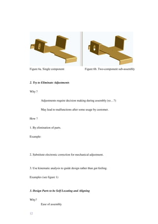
emphasis was to relate Product design, Assembly operations, and Assembly Method to
the single decision factor: the cost. We shall study the Boothroyd method in detail. Note
that there are other systems based on very similar principals: The Hitachi Assembly
Evaluation Method, developed at Hitachi in Japan, used very similar ideas.
Basic idea: reduction of cost of a product through simplification of its design.
How ?
- Reduction of number of components
- Ensuring that parts are easy to assemble
- Increasing the use of standardized parts across entire product range
- Designing with widest possible tolerances
- Material selection must consider manufacturing also, not just function.
4. 4
Why do these ideas work ?
Fewer components in a design imply:
Manual assembly:
Fewer assembly operations Æ fewer assembly workers
Automated assembly:
Reduction of one entire section of Assembly station
Fewer fixtures/jigs, feeders, etc.
Also, fewer parts usually mean smaller stacked tolerances, and therefore lead to better
functioning of the assemblies, and fewer rejects (why ?)
The Boothroyd-Dewhurst method includes:
Preliminary (rough) design
Selection of Assembly Method (manual, robotic, or high-speed automated)
Design/Redesign of product for selected method
The selection of assembly method must be done at an early stage in the product design
process (why?). One factor that affects this decision is the production volume (that is,
forecast demand).
Low volume (< 1000 parts per year) => manual assembly
High volume (> million parts per year) => high-speed automated assembly
Somewhere in between these limits, and based on some other considerations (labour
costs, technical requirements, e.g. in spray painting) robotic assembly may be optimal.
Typical hardware involved in each method, and its characteristics are listed below.
Manual Assembly:
Benches or simple conveyors
Assembly station has bins with un-oriented parts
Simple jigs and fixtures with manual clamping
Simple, light tools (manual/pneumatic/electric screwdrivers, solder irons etc.)
Inexpensive setup costs
Assembly costs are nearly constant, and independent of volume (why ?)
5. 5
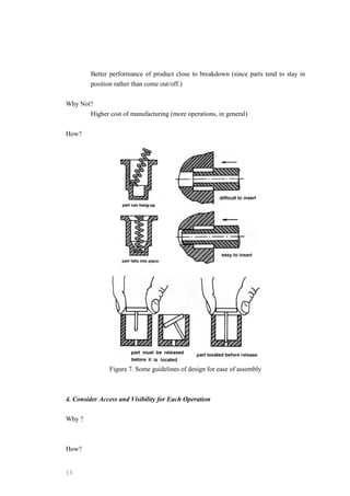
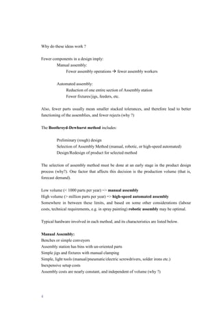
High-speed (Special Purpose) Transfer Assembly:
Machines are built to produce specific product.
Components:
Part feeders [indexed/asynchronous]
Single purpose workheads
Transfer devices (usually equipped with workheads)
Very expensive and time-consuming to build
Very high production rate
Down time due to defective parts may be a severe problem
[Example: defective part-mix in a bowl-feeder]
Implication: incoming QC must be stringent
Inflexible: changing hard-automation system requires fabrication of new
jigs/fixtures/machines and may take a long time and cost a lot.
Robotic Assembly
Similar to non-synchronous special purpose assembly stations, except robots replace the
single-purpose workheads.
Use of robots allows flexibility in product types and production rates.
Figure 3. Common assembly automation devices [source Boothroyd 91]
6. 6
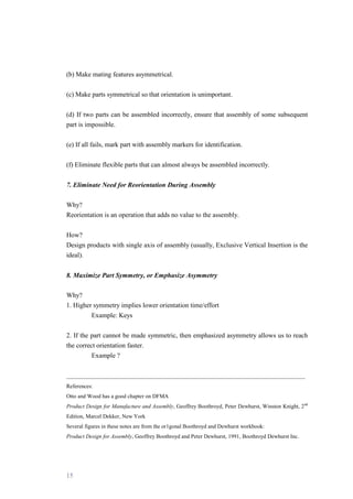
Design for Manual Assembly
The Boothroyd Dewhurst method provides a quantitative measure called the design
efficiency based on analysis of a product. The efficiency compares the total assembly
time for a product with the total assembly time for an ideal product (determined by a
method suggested by the authors). The efficiency can be used to compare various designs
in terms of their relative efficiencies (for manual assembly).
The design improvement is brought about by two considerations:
1. A decision is made as to whether the part can be considered a candidate for
elimination, or combination with other parts of the assembly
2. An estimation of the time taken to grasp, manipulate, and insert the part.
The procedure:
STEP 1. Obtain design details
Engineering drawings, or Exploded 3-D views, or Existing product, or Prototype
STEP 2.. Take assembly apart (or imagine doing so) -- assigning identification to each
part as it is removed.
Consider sub-assemblies as parts, and analyse them separately (recursively).
STEP 3. Begin re-assembly of the product. Start with the part with the highest
identification number, going all the way up to the part 1.
Fill up the assembly worksheet as you go along.
[note: the method requires that the product is assembled one part at a time. In reality,
assembly workers use both hands and often assemble two parts in a step. However, a
change in the assembly procedure will correspondingly change the assembly time for the
ideal product -- thereby keeping the efficiency constant.]
STEP 4. Compute the design efficiency, given as:
EM = 3 x NM / TM
7. 7
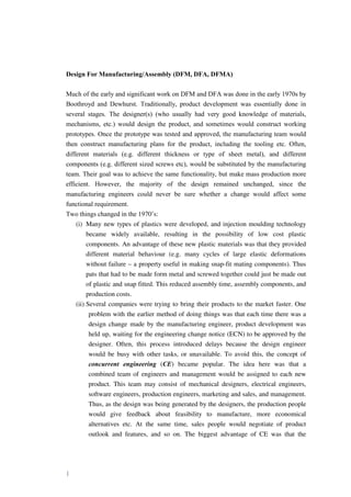
We go through an example to see how the method works.
Figure 4. A piston-assembly design [source Boothroyd 91]
The computation is done by systematically completing the data in the following table.
The data requires several estimates for assembly efficiency of different components based
on their characteristics. This data is compiled empirically – by a large number of time-
motion studies conducted over may years. We will use the charts from Boothroyd
(handouts given in class).
8. 8
c1 c2 c3 c4 c5 c6 c7 c8 c9
Part
ID
No
of
times
the
operation
is
carried
out
consecutively
Manual
handling
code
Manual
handling
time
per
part
Manual
insertion
code
manual
insertion
time
per
part
Operation
time
c2(
c4
+
c6)
Operation
cost
0.4
c7
Estimation
for
theoretical
minimum
parts
Name of
Assembly
Total:
TM CM NM
Design efficiency =
3 NM/TM =
Table 1. Table for computation of Design efficiency (Source: Boothroyd 91).
One of the key features of the Boothroyd-Dewhurst method is estimation of the ideal
product -- which translates to the method of filling up column 9 in the chart. They give
the following guidelines:
Rule 1. During operation of the product, does the part move relative to all other parts
already assembled?
Rule 2. Must the part be of a different material than the parts already assembled? [Only
fundamental reasons associated with material properties are acceptable.]
Rule 3. Must the part be separate from all parts already assembled (because otherwise
necessary assembly/disassembly of other parts would be impossible)?
If the answer to any of these questions is YES, a 1 is entered in column 9 (except if there
are multiple parts in column 2, in which case the minimum number of separate parts
required is entered in column 9.)
9. 9
c1 c2 c3 c4 c5 c6 c7 c8 c9
Part
ID
No
of
times
the
operation
is
carried
out
consecutively
Manual
handling
code
Manual
handling
time
per
part
Manual
insertion
code
manual
insertion
time
per
part
Operation
time
c2(
c4
+
c6)
Operation
cost
0.4
c7
Estimation
for
theoretical
minimum
parts
Name of
Assembly
PNEUMATIC
PISTON
6 1 30 1.95 00 1.5 3.45 1.38 1 MAIN BLOCK
5 1 10 1.5 10 4.0 5.50 2.2 1 PISTON
4 1 10 1.5 00 1.5 3.00 1.2 1 PISTON STOP
3 1 05 1.84 00 1.5 3.34 1.34 1 SPRING
2 1 23 2.36 08 6.5 8.86 3.54 0 COVER
1 2 11 1.8 39 8.0 16.6 6.64 0 SCREW
40.75 16.3 4
Total:
TM CM NM
Design efficiency =
3 NM/TM = 0.29
Table 2. Evaluating the design efficiency of Piston
Improving the design:
The following considerations are important:
STEP 1. Is the number in column 9 < the number in column 2 ?
If yes, there is an opportunity for reduction in number of parts.
STEP 2. Examine columns 4 and 6. These figures indicate potential for assembly time
reduction.
Based on these ideas, a redesign of the piston assembly is presented below. Notice how
the new design presents a design efficiency of 90%.
10. 10
Figure 5. An improved piston design [Source: Boothroyd 91]
c1 c2 c3 c4 c5 c6 c7 c8 c9
Part
ID
No
of
times
the
operation
is
carried
out
consecutively
Manual
handling
code
Manual
handling
time
per
part
Manual
insertion
code
manual
insertion
time
per
part
Operation
time
c2(
c4
+
c6)
Operation
cost
0.4
c7
Estimation
for
theoretical
minimum
parts
Name of
Assembly
NEW
PNEUMATIC
PISTON
4 1 30 1.95 00 1.5 3.45 1.38 1 MAIN BLOCK
3 1 10 1.5 00 1.5 3.00 1.2 1 PISTON
2 1 05 1.84 00 1.5 3.34 1.34 1 SPRING
1 1 10 1.5 30 2.0 3.50 1.40 1 COVER and STOP
13.29 5.32 4
Total:
TM CM NM
Design efficiency =
3 NM/TM = 0.90
Table 3. Evaluating the design efficiency of the re-designed piston
11. 11
Guidelines for improving design (for assembly) of mechanical products:
1. Reduce Part Count and Part Types
Why ?
Lower material cost
Reduced jigs/fixtures cost
Improved quality
Less documentation
Small inventories
Fewer suppliers
Simplified production control
Fewer Inspections
Less rework
How ?
1. Check the need for the part’s existence (apply the three rules above).
2. Eliminate separate fasteners when possible.
3. Design multi-functional parts by maximum use of the capabilities of individual
manufacturing processes. For example, use near-net shape moulding and casting when
possible to reduce part count.
4. Eliminate product features that are of no value to the customer.
5. Do not over-use piece part producibility guidelines in early stages of design -- they lead
to simplified production of individual parts, but much higher part count.
Example: In figure 6, the single component design has potentially higher waste (since an
irregular shape must be cut out of the stock sheet; but the assembly cost for the second
design is much higher.
12. 12
Figure 6a. Single component Figure 6b. Two-component sub-assembly
2. Try to Eliminate Adjustments
Why ?
Adjustments require decision making during assembly (so…?)
May lead to malfunctions after some usage by customer.
How ?
1. By elimination of parts.
Example:
2. Substitute electronic correction for mechanical adjustment.
3. Use kinematic analysis to guide design rather than gut feeling.
Examples (see figure 1)
3. Design Parts to be Self Locating and Aligning
Why?
Ease of assembly
13. 13
Better performance of product close to breakdown (since parts tend to stay in
position rather than come out/off.)
Why Not?
Higher cost of manufacturing (more operations, in general)
How?
Figure 7. Some guidelines of design for ease of assembly
4. Consider Access and Visibility for Each Operation
Why ?
How?
14. 14
1. Ensure adequate clearance for hands, tools, testing probes etc.
2. Ensure that the assembly worker has clear visibility of the mating features.
5. Consider Handling Part from Bulk
Why?
Some parts are easily handled when alone, but create a mess when mixed in large
numbers.
How?
1. On parts that mate using interlocking tapers, include features that prevent nesting.
2. On parts with combinations of holes, projections, gaps and cut-outs -- there is high
probability of tangling.
Close gaps; Enlarge projections; Use closed-end coil springs;
3. Avoid parts which are fragile or sharp, unless functionally necessary. If necessary,
include safe-handling features.
4. Avoid use of flexible parts -- if flexible parts are needed, try using those that retain
shape when handled.
5. Avoid parts that require special tools for the worker to perform assembly.
6. Design Parts that Cannot be Installed Incorrectly
Why?
Example: Styrofoam packing for TV/Stereo.
How?
(a) Provide projections that will disallow incorrect assembly.
15. 15
(b) Make mating features asymmetrical.
(c) Make parts symmetrical so that orientation is unimportant.
(d) If two parts can be assembled incorrectly, ensure that assembly of some subsequent
part is impossible.
(e) If all fails, mark part with assembly markers for identification.
(f) Eliminate flexible parts that can almost always be assembled incorrectly.
7. Eliminate Need for Reorientation During Assembly
Why?
Reorientation is an operation that adds no value to the assembly.
How?
Design products with single axis of assembly (usually, Exclusive Vertical Insertion is the
ideal).
8. Maximize Part Symmetry, or Emphasize Asymmetry
Why?
1. Higher symmetry implies lower orientation time/effort
Example: Keys
2. If the part cannot be made symmetric, then emphasized asymmetry allows us to reach
the correct orientation faster.
Example ?
References:
Otto and Wood has a good chapter on DFMA
Product Design for Manufacture and Assembly, Geoffrey Boothroyd, Peter Dewhurst, Winston Knight, 2nd
Edition, Marcel Dekker, New York
Several figures in these notes are from the or1gonal Boothroyd and Dewhurst workbook:
Product Design for Assembly, Geoffrey Boothroyd and Peter Dewhurst, 1991, Boothroyd Dewhurst Inc.