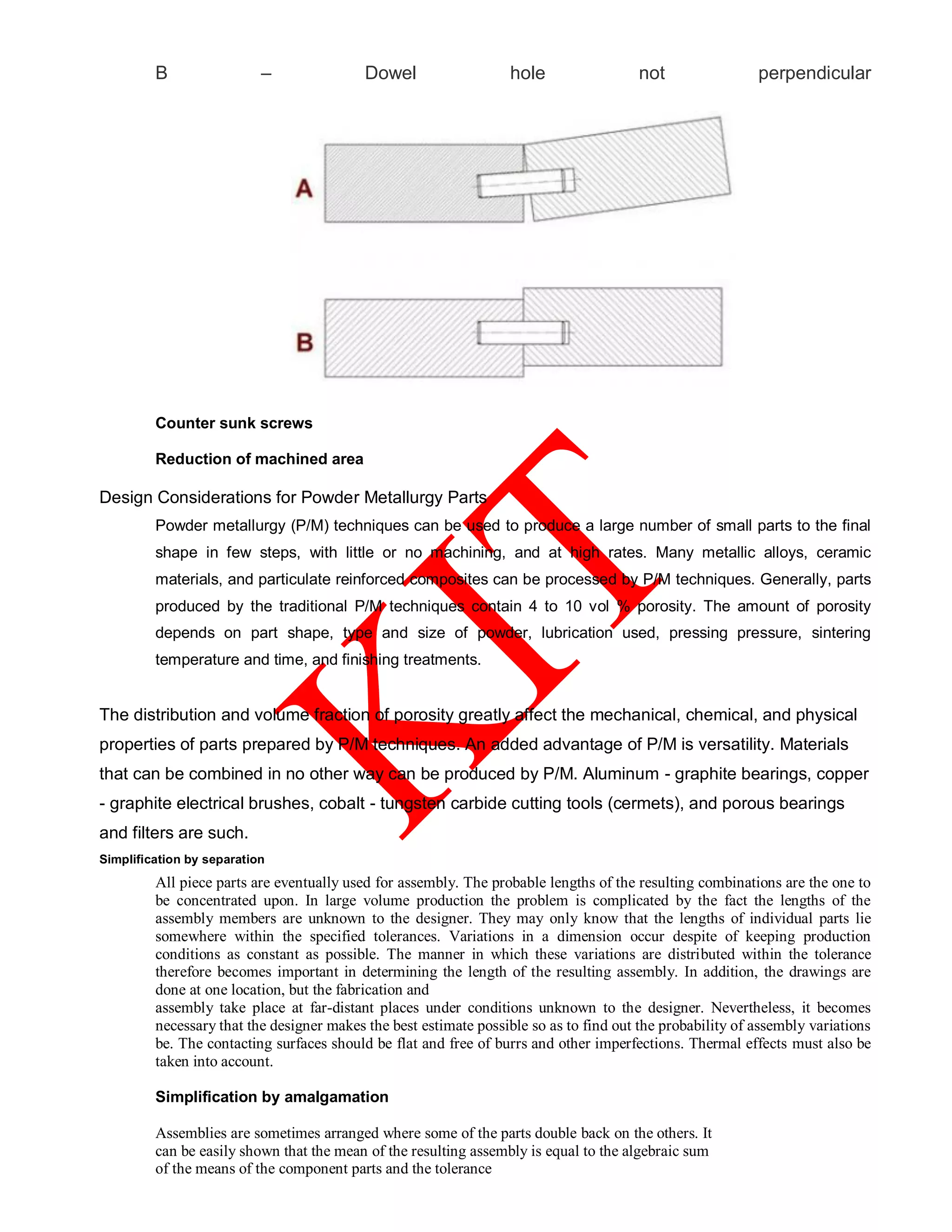
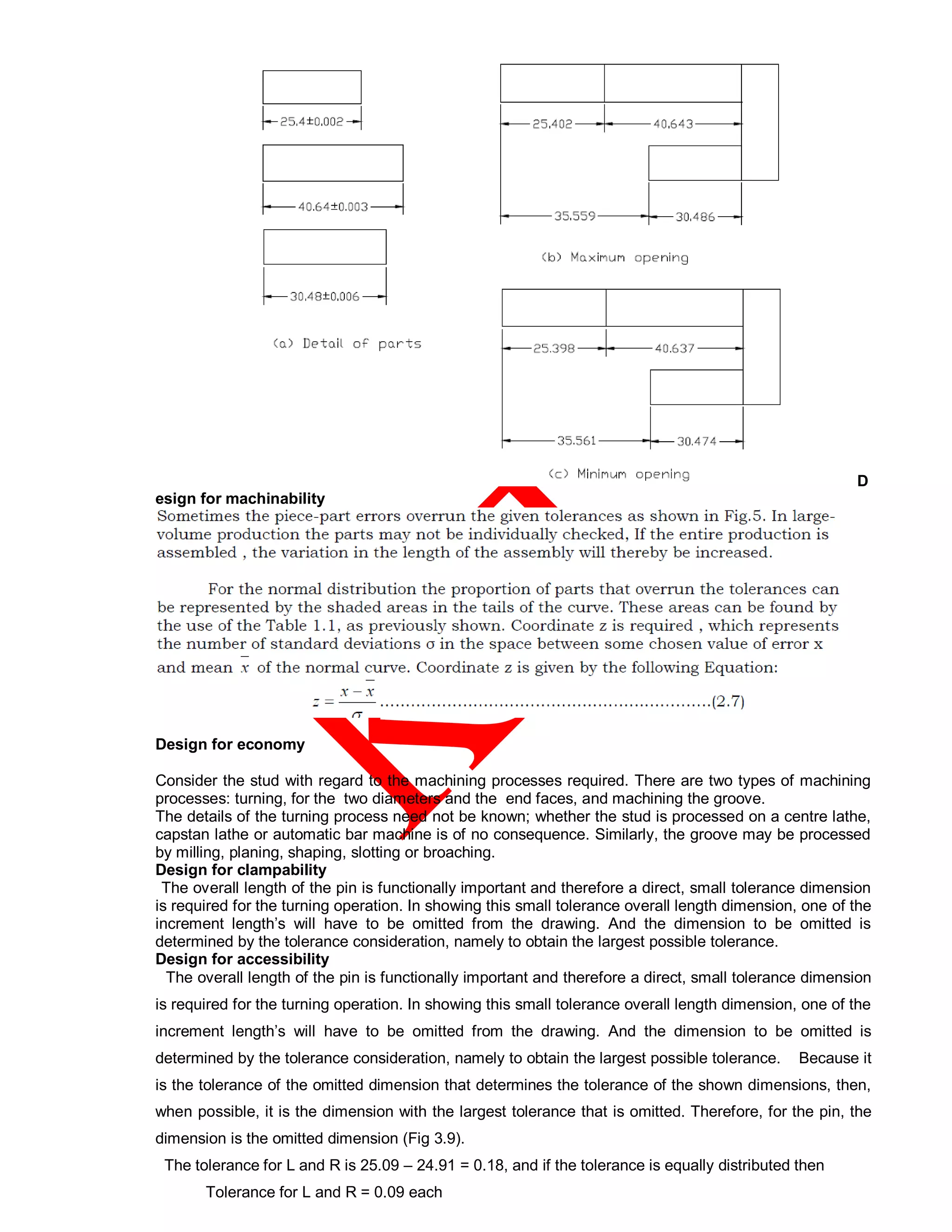
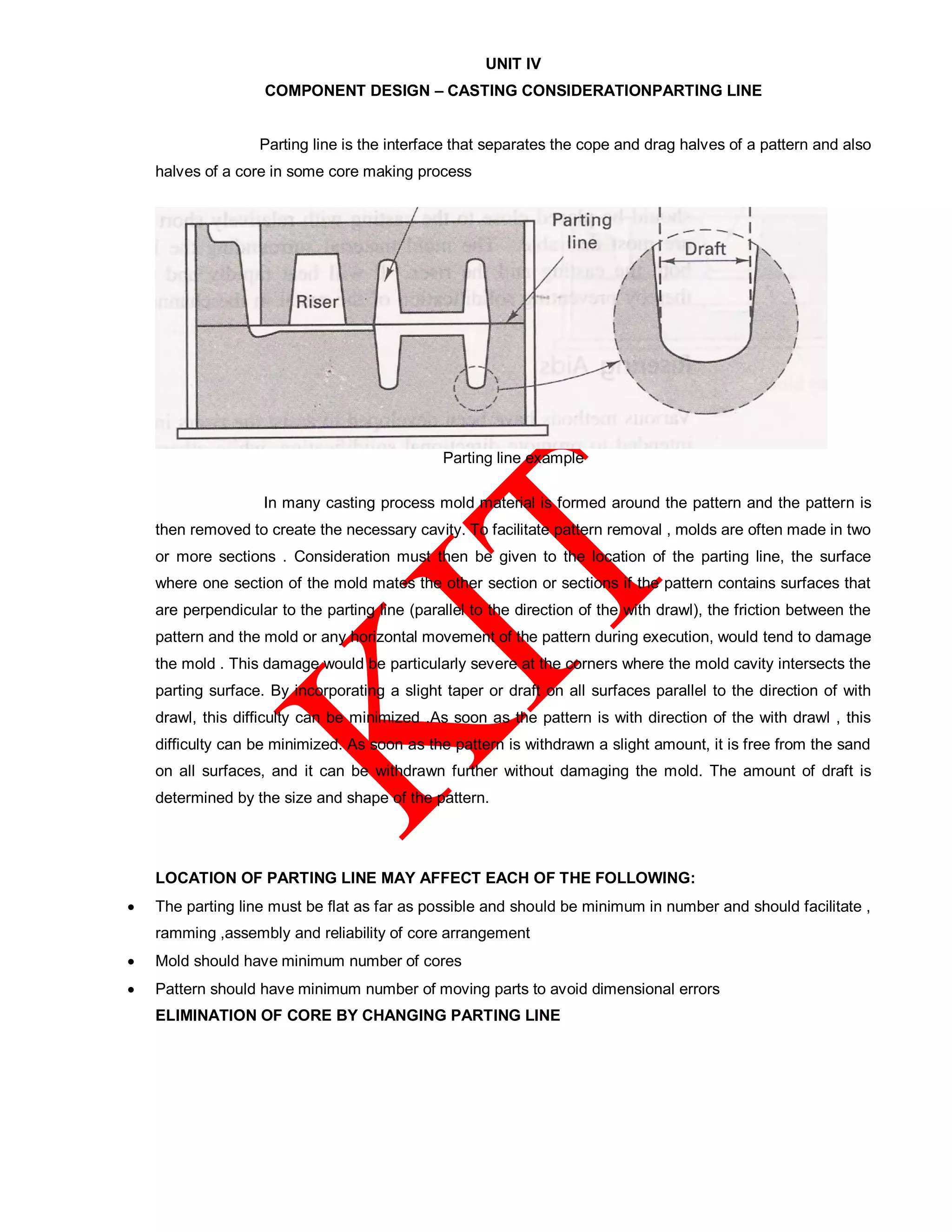
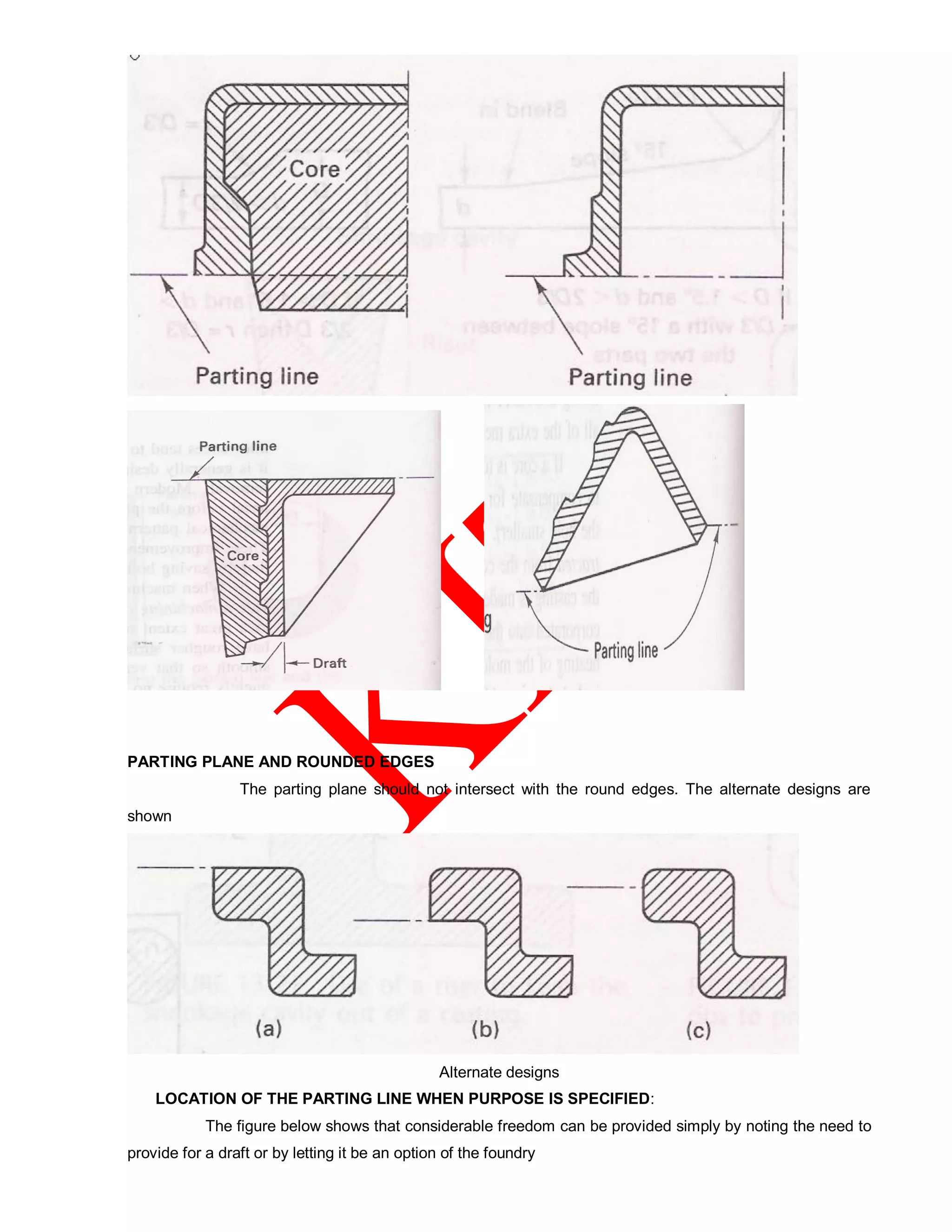
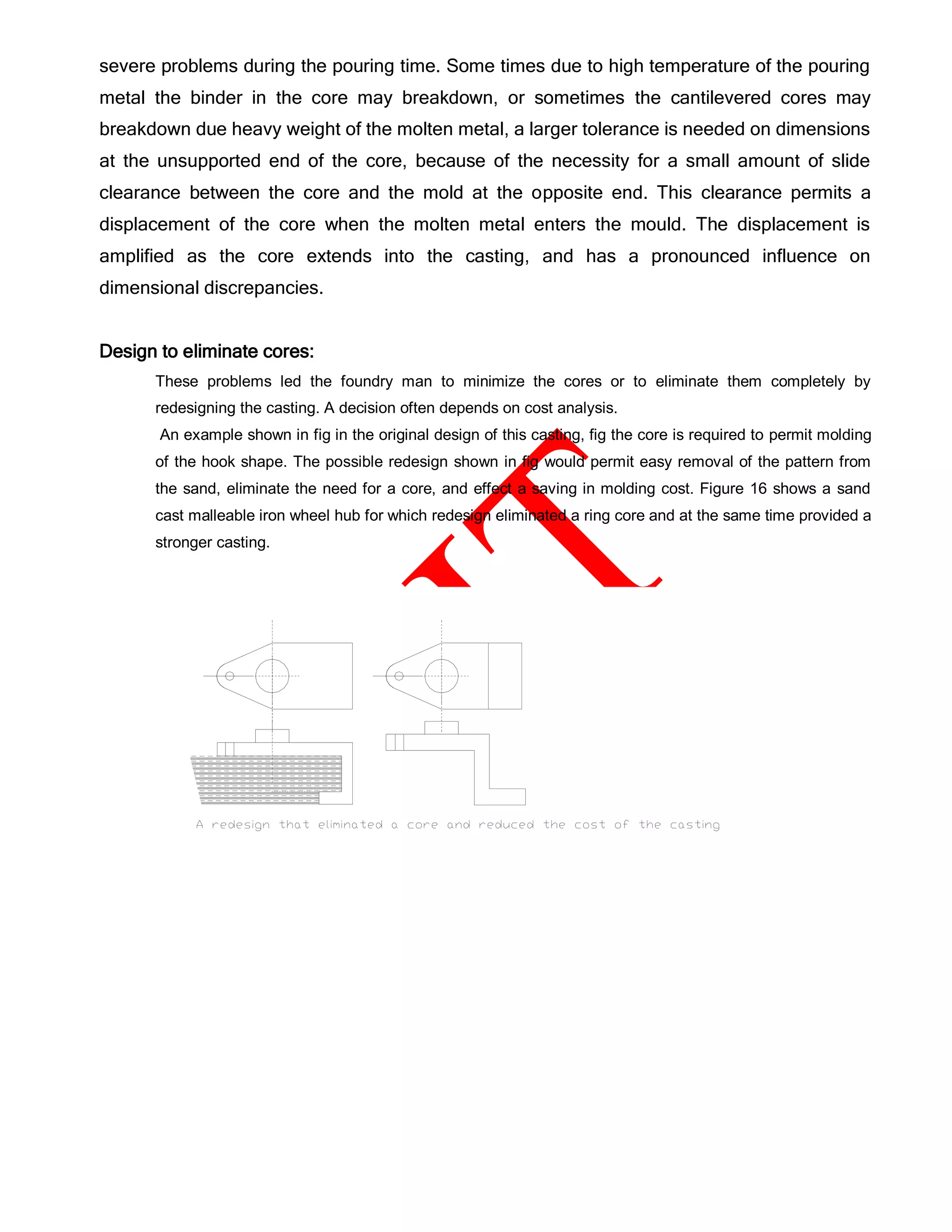
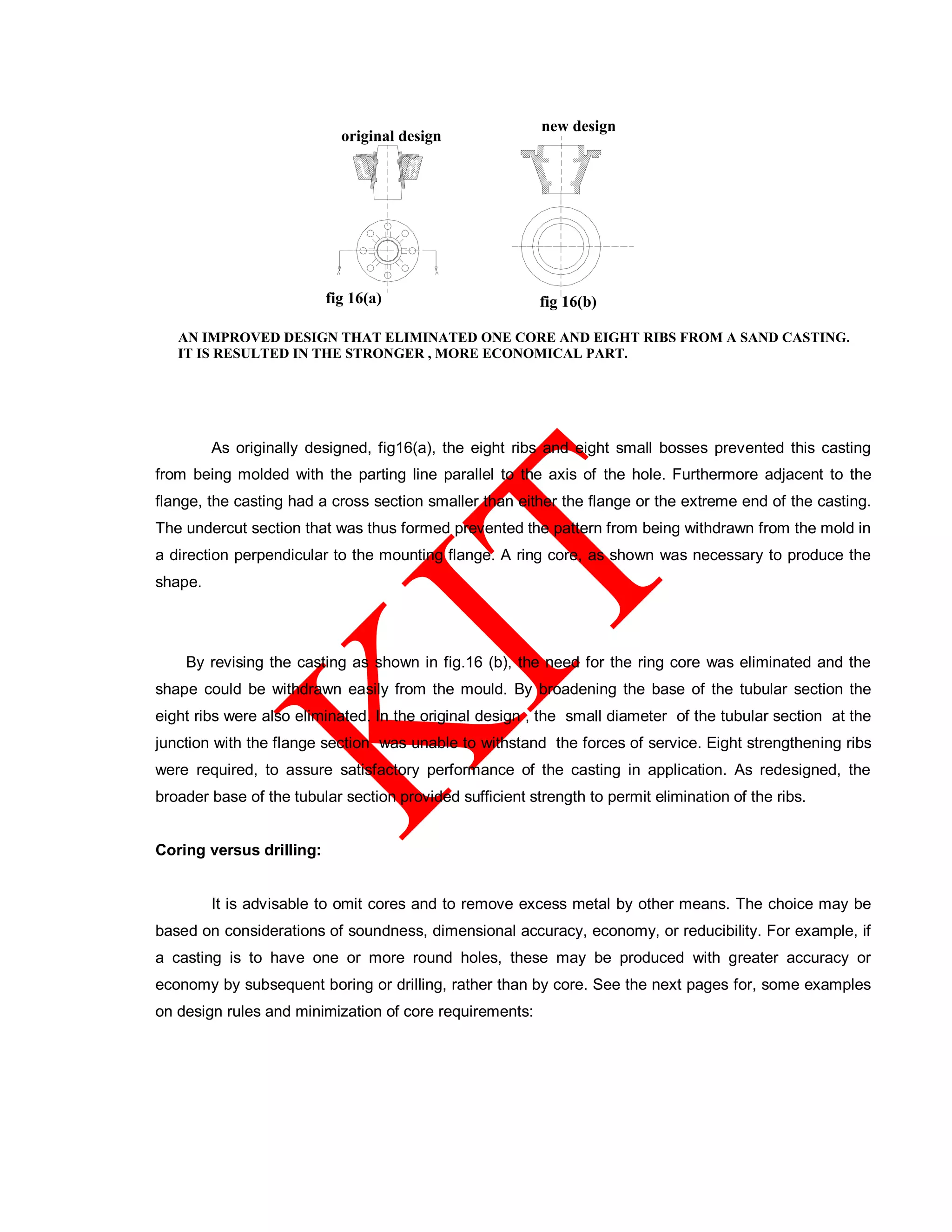
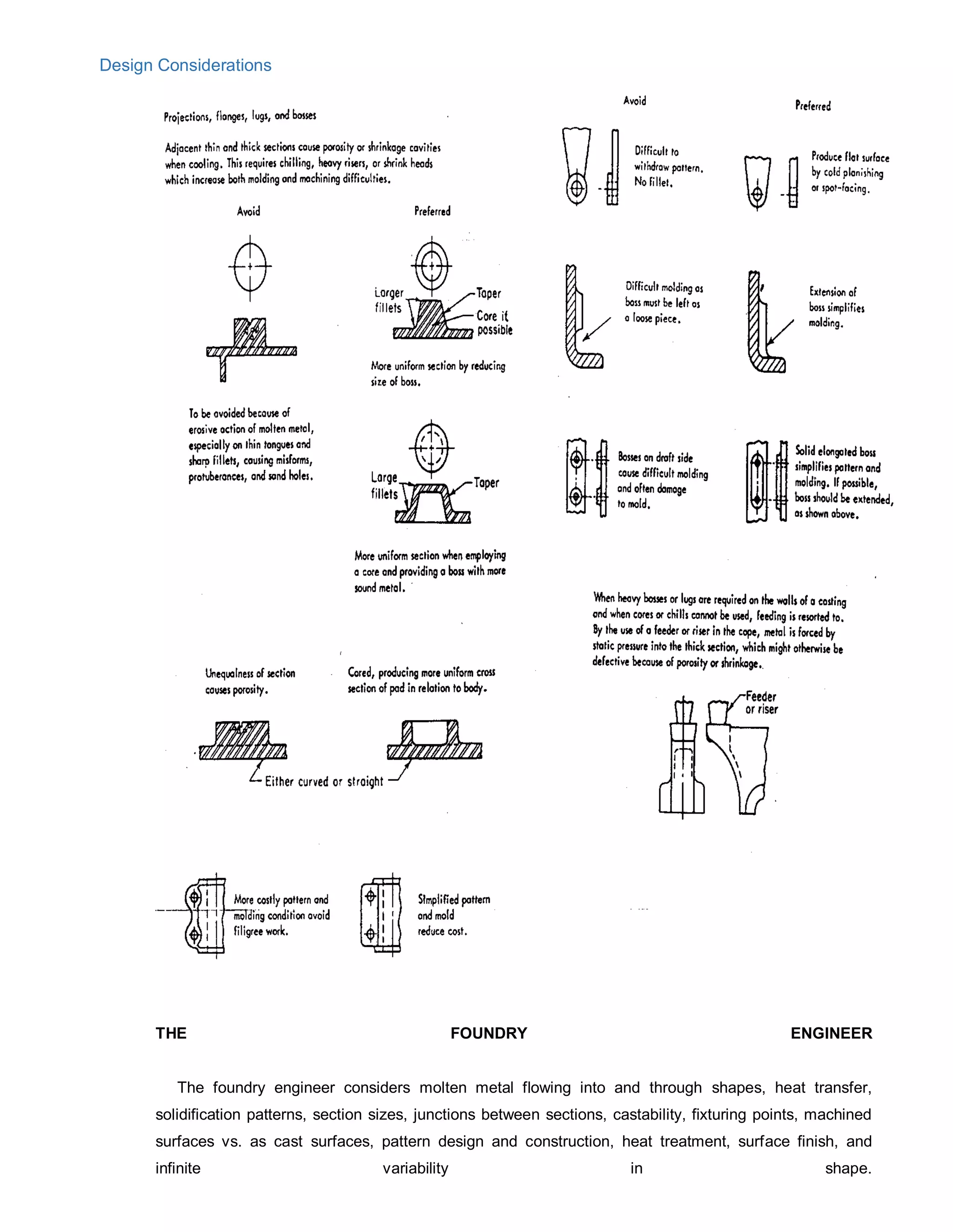
Downloaded 169 times
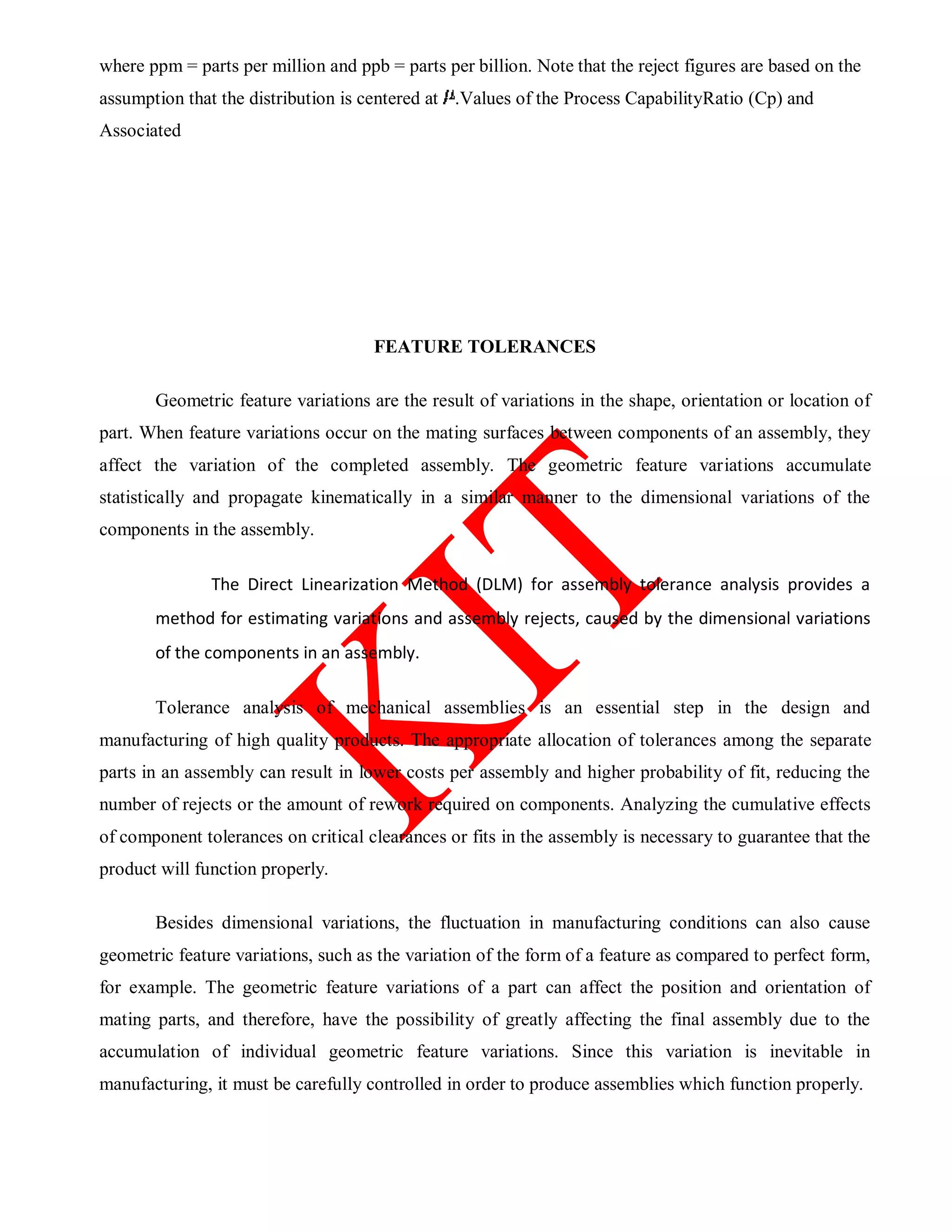
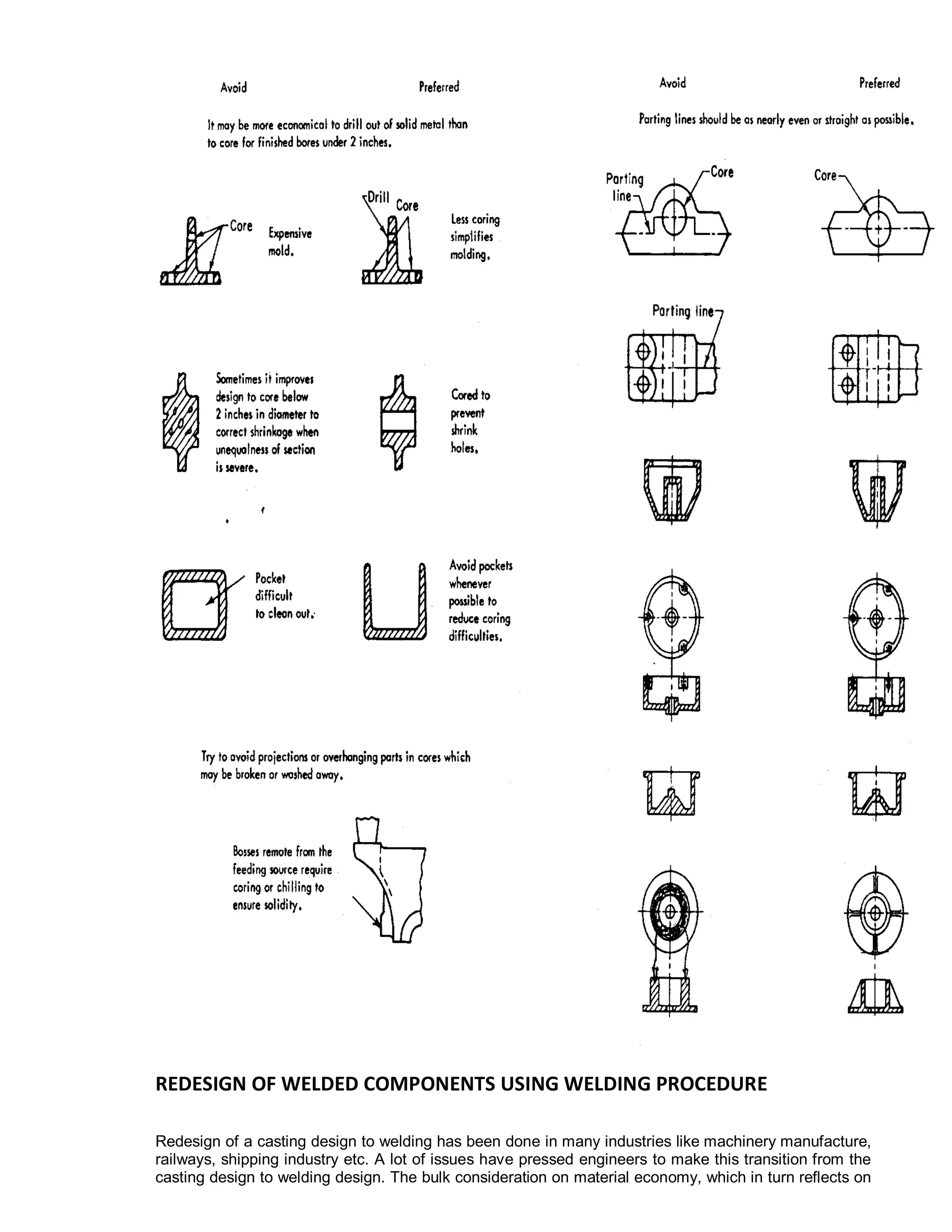
![Figure 2. Adjustment due to geometric shape variations
assembly, the cylinder makes contact on a peak of the lower contact surface, while the next assembly
may make contact in a valley. Similarly, the lower surface is in contact with a lobe of the cylinder,
while the next assembly may make contact between lobes.
Local surface variations such as these can propagate through an assembly and accumulate just as
dimensional variations. Thus, in a complete assembly model all three sources of variation, that is,
dimensional and geometric feature variations and kinematic adjustments, must be accounted for to
assure realistic and accurate results.
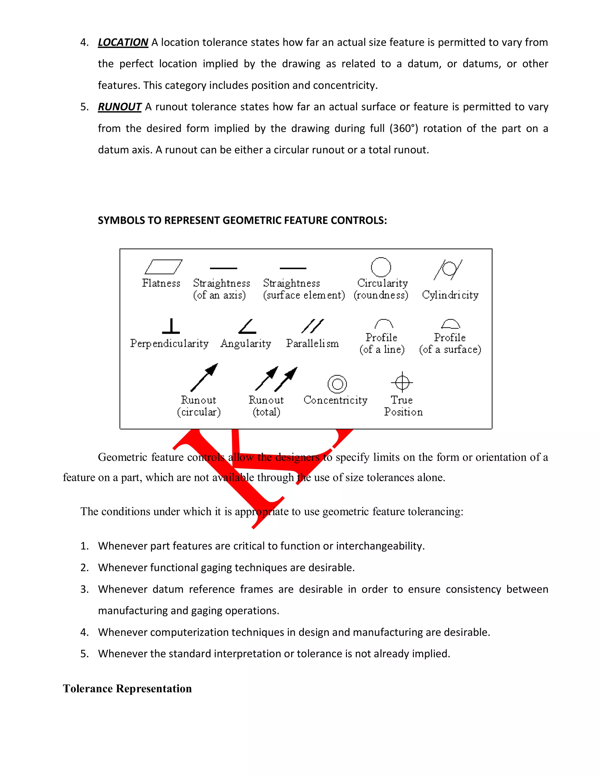
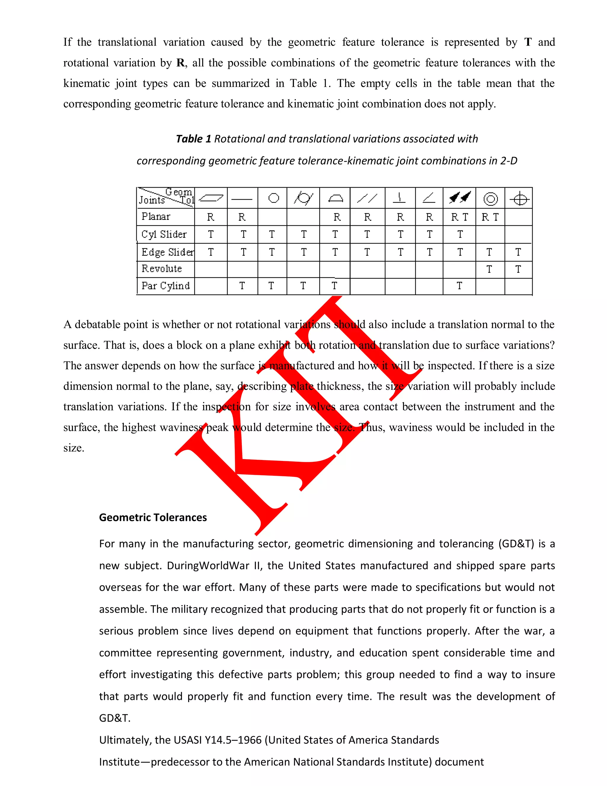
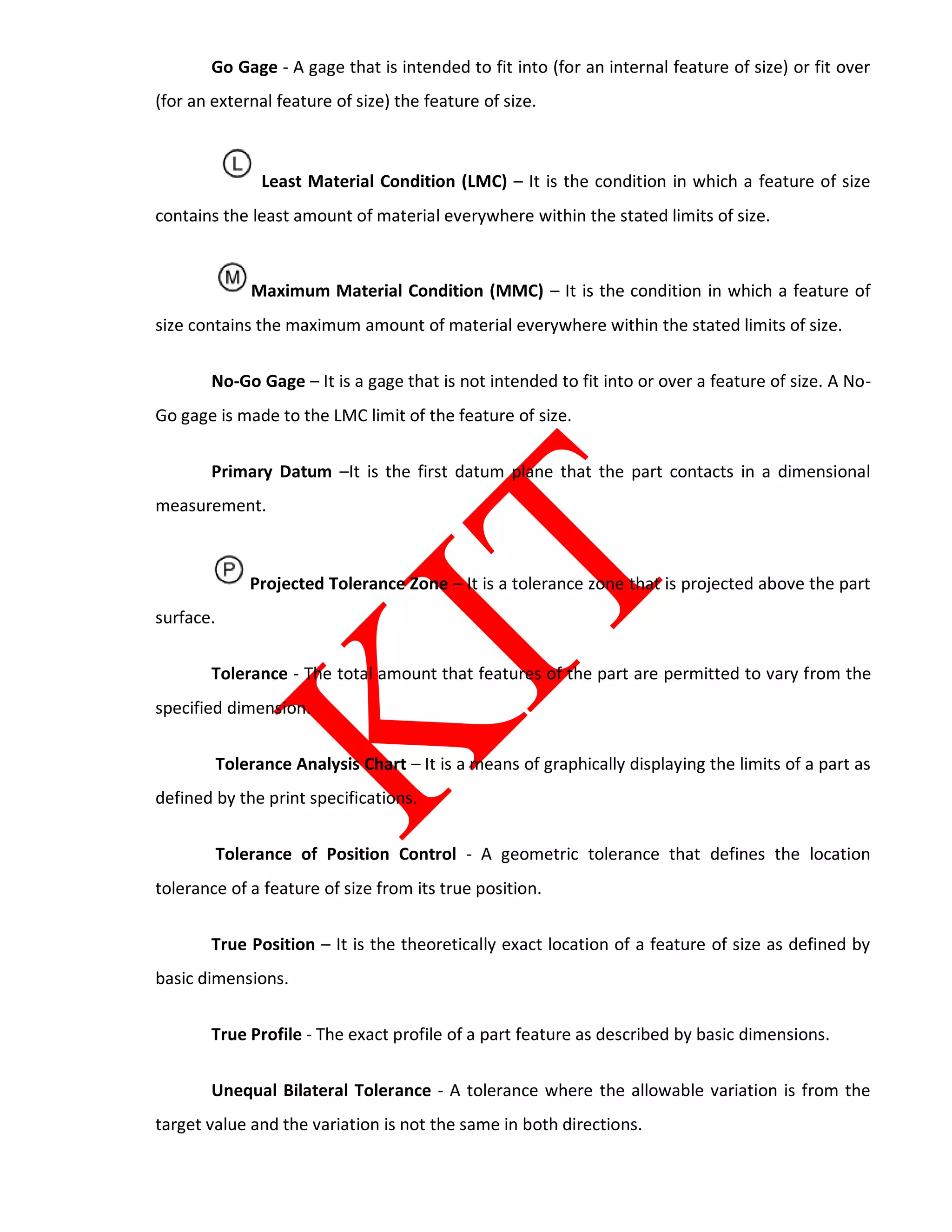
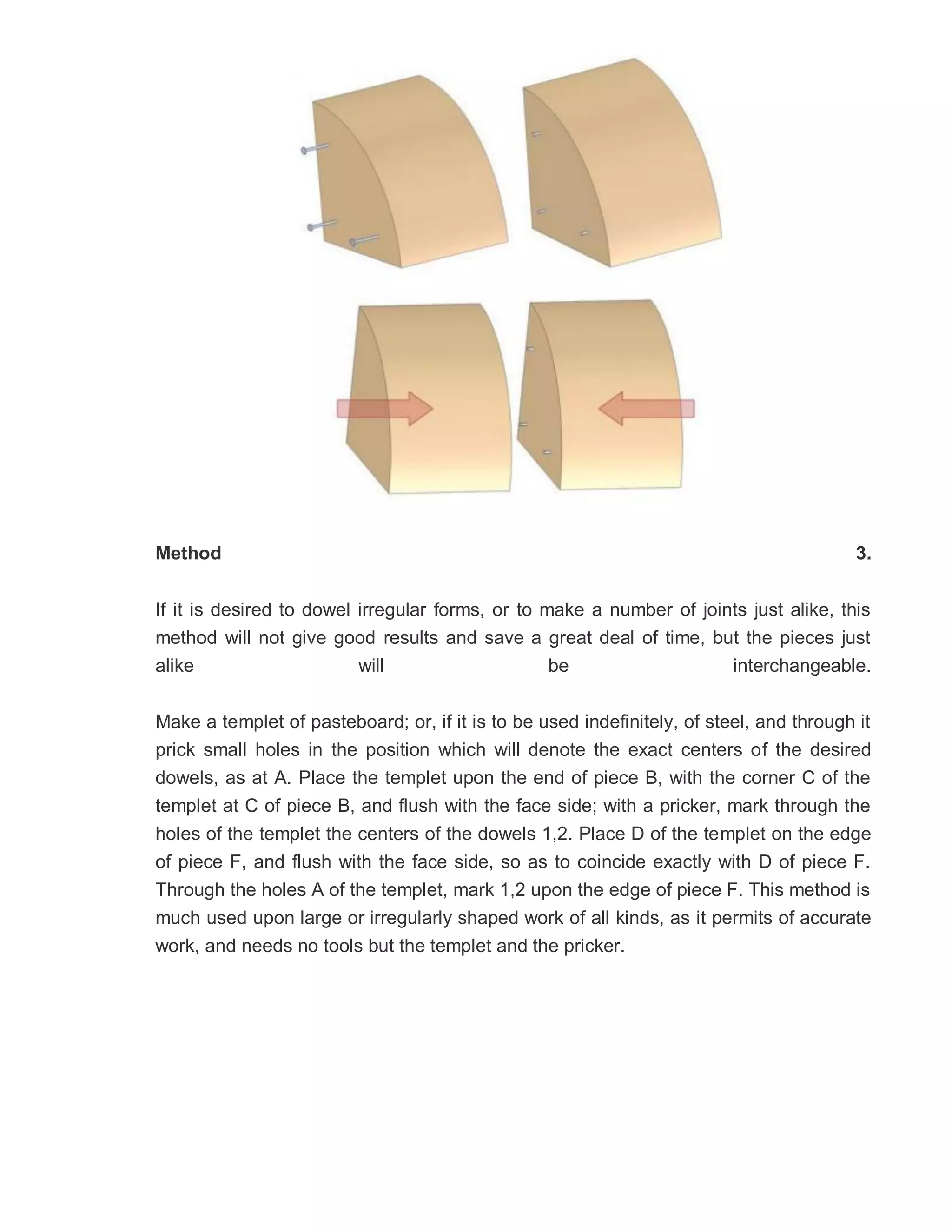
Definitions
The geometric feature tolerances defined by ANSI Y14.5M-1982 fall into five main groups, according
to Foster [1992]:
1. FORM A form tolerance states how far an actual surface or feature is permitted to vary from
the desired form implied by the drawing. It includes flatness, straightness, circularity and
cylindricity.
2. PROFILE A profile tolerance states how far an actual surface or feature is permitted to vary
from the desired form on the drawing and/or vary relative to a datum or datums. Profile of a
line and profile of a surface are the only two types of profile tolerance.
3. ORIENTATION An orientation tolerance states how far an actual surface or feature is
permitted to vary relative to a datum or datums. It consists of perpendicularity, angularity and
parallelism.](https://image.slidesharecdn.com/edcc7201dfmaenotes-180418073631/75/ED-CC7201-DFMAE_notes-13-2048.jpg)
![Schemes for tolerance representations or characterizations in an assembly have been developed with
the increasing use of solid modeling tools in product design. These schemes can be generally classified
into three groups:
1. Set theoretic model
2. Offset zones
3. Parametric zones
The set theoretic model of tolerances describes a variational class of objects (or parts) which is defined
by the tolerances applied to the nominal object. This variational class is modeled as a set of points in 3-
D space, which contains the nominal object but does not force any part of the object's real boundary to
be in an exact position [Shah & Miller 1990]. The set theoretic model has not been implemented
because it is difficult to mathematically describe objects in terms of its theory [Robison 1989].
Offset zones are created by offsetting the nominal boundary of a part by an amount equal to the
tolerance on either side of the nominal [Requicha 1983]. Offsets are obtained for the maximum
material condition (MMC) and for the least material condition (LMC). The difference between these
two zones comprises the tolerance zone, an envelope within which the boundary of the part must lie
[Shah & Miller 1990]. This method seems to lend itself to the use of "go-no go" gages to check the
tolerance condition of a part. A disadvantage of this method is that it assumes that all surfaces remain
in the same orientation as the nominal surface. It has not be used to model variations in the orientation
of a surface, such as angularity [Robison 1989].
A parametric zone or space is composed of a set of parameters or dimensions and constraints which
describe the nominal shape of the geometry [Hillyard & Braid 1978, Martino & Gabriele 1989].
Tolerances are treated as small variations in these parameters. This type of tolerance model is closely
related to the variational geometry approach for CAD modelers [Shah & Miller 1990, Guilford &
Turner 1993]. The advantage of this model is that it uses the constraints and parameters of the
geometry to create a set of equations which may be solved to determine any unknown dimensions or
variations [Gupta & Turner 1993].
A combination of parametric zone and offset zone for representing tolerances in an assembly has been
recently proposed by Gilbert [1992]. They use the 4x4 homogeneous transformation matrix to contain
the nominal relations between parts and variations allowed by the tolerances in an assembly tolerance
model. Most geometric feature variations, except for form tolerances, can be represented by this
method.](https://image.slidesharecdn.com/edcc7201dfmaenotes-180418073631/75/ED-CC7201-DFMAE_notes-15-2048.jpg)
![The assembly tolerance analysis model adopted by this paper is a parametric zone type. It is composed
of a vector-based method for modeling 3-D mechanical assemblies, which utilizes vectors to represent
dimensions between critical part features and includes a set of kinematic joint types to represent
mating conditions between parts at the contact locations [Chase, Gao & Magleby 1994]. This method
also includes guidelines for identifying a valid set of vector loops to ensure that the tolerance model is
complete. This method lays the vector-loop-based assembly tolerance model over the solid model, and
can be connected with a tolerance analysis package to solve for the variations on the desired
dimensions or clearances. This model is also capable of including component geometric feature
tolerances.
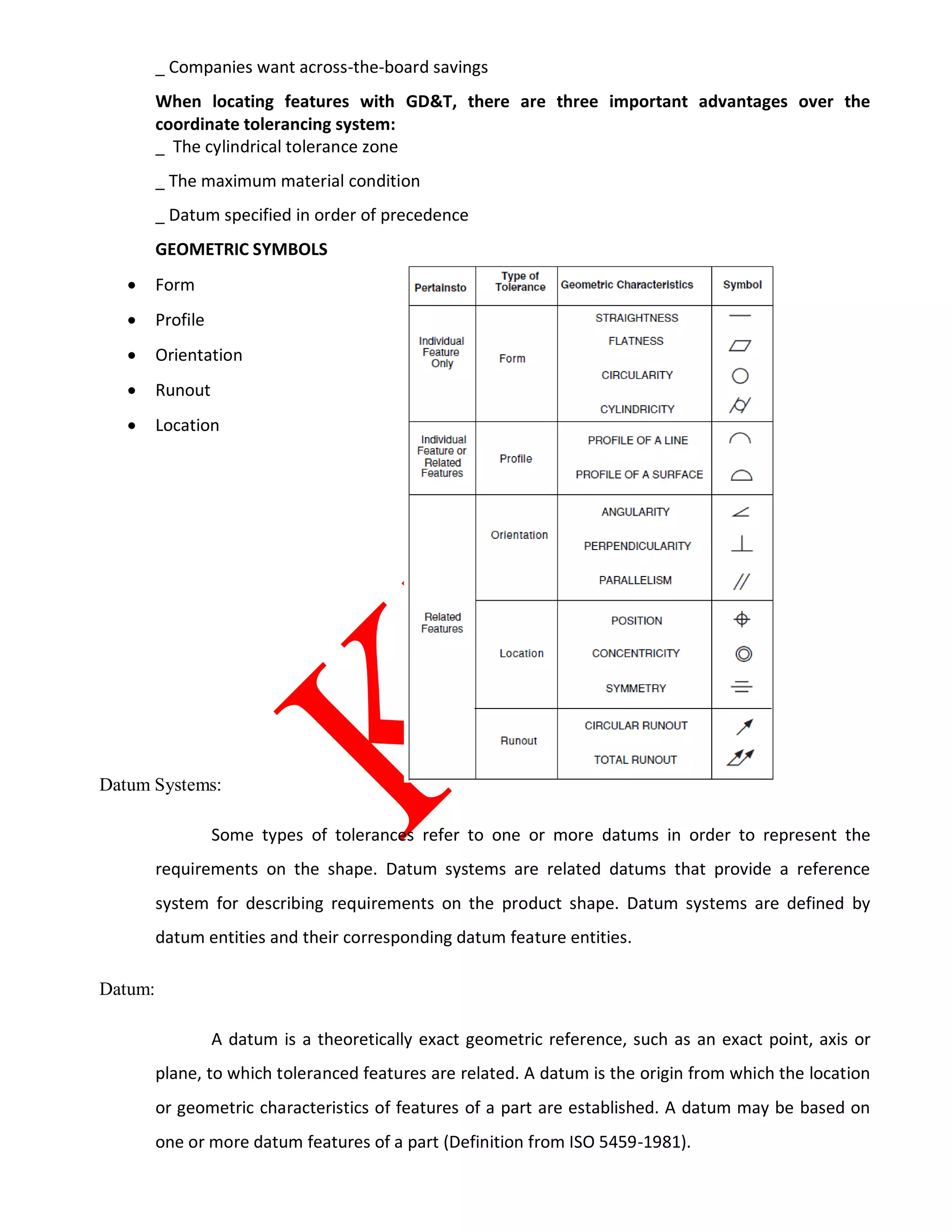
Characterizing Geometric Feature Variations
The geometric feature variations defined in the ANSI standard must be modeled so that their effects
will be reflected in the tolerance model of the assembly. By analyzing the assembly constraint
equations, the effects of the geometric feature variations on the assembly or kinematic variables can
then be estimated. In the vector-loop-based assembly tolerance model, this is done by modeling the
geometric feature variations with zero length vectors having specified variations or tolerances, placed
at the contact point between mating surfaces. These zero length vectors are considered as independent
variation sources to the dimensional variations in the assembly. The direction in which they introduce
variation into an assembly depends on the type of contact which exists between the surfaces. For this
reason, geometric feature tolerances of components in an assembly are related to the joint types
through which the geometric feature variations are propagated.
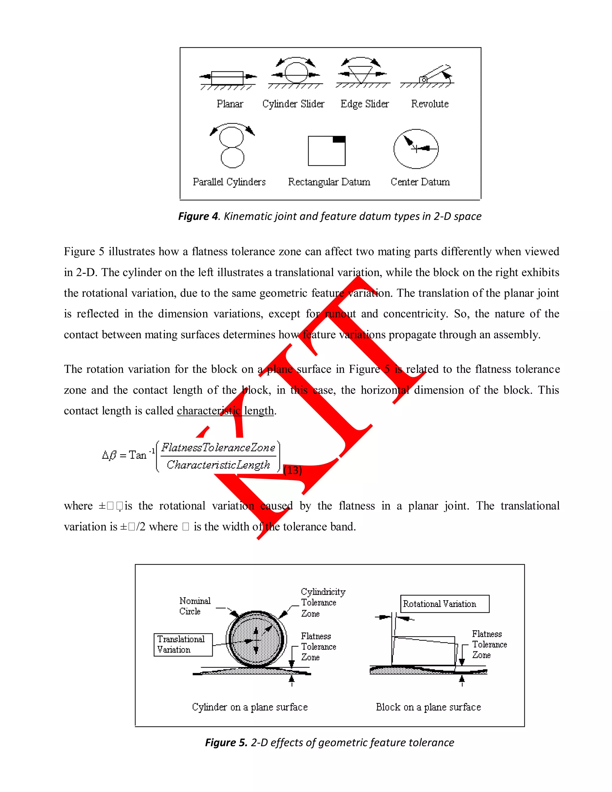
Geometric Feature Tolerance Modeling in 2D
The kinematic joint type and geometric feature tolerances on the parts in contact are the key elements
in analyzing the effect of the geometric feature tolerances on assembly variations. The commonly used
kinematic joint types in 2-D space are modeled in Figure 4 [Chase, Gao & Magleby 1994, Chun 1988].
The effect of the geometric feature tolerances associated with each of the joints may result in
translational variation or rotational variation. This translational or rotational variation is usually
smaller than the size tolerances on the same parts.](https://image.slidesharecdn.com/edcc7201dfmaenotes-180418073631/75/ED-CC7201-DFMAE_notes-16-2048.jpg)


![“Design, if it is to be ecologically responsible and socially responsive,
must be revolutionary and radical in the truest sense.
It must dedicate itself to nature’s principle of least effort. […]
That means consuming less, using things longer, recycling materials,
and probably not wasting paper printing books.”
Victor Papanek, Design for the Real World, 1971
The IMPORTANCE of the DESIGN STAGE:
70% of costs of product development, manufacture and use are decided in early
design stages
(1991 National Research Council Report titled “Improving Engineering Design”)
Examples:
GM truck transmissions: 70% of costs decided at
design stage
Rolls Royce: 80% of costs decided at design stage, as determined from an average among
2000 parts
Likewise, it is clear that most decisions that affect future environmental
impacts are made at the design stage.
2](https://image.slidesharecdn.com/edcc7201dfmaenotes-180418073631/75/ED-CC7201-DFMAE_notes-78-2048.jpg)

This document provides an overview of design for manufacturing and assembly (DFMA) principles. It discusses general design principles for manufacturability, including simplifying designs, standardizing parts, designing for ease of fabrication and assembly, and designing within production process capabilities. Specific guidelines are provided for various manufacturing processes. Process capability and how it relates to a manufacturing process meeting specifications is also introduced.


![Electrical discharge machining [EDM]](https://cdn.slidesharecdn.com/ss_thumbnails/electricaldischargemachiningedm-170803232011-thumbnail.jpg?width=640&height=640&fit=bounds)