2
Lecture Objectives
• DiscussI/O data transfer techniques
• Interrupt driven I/O
• Direct Memory Access (DMA)
• Input Output Processor (IOP)
3.
3
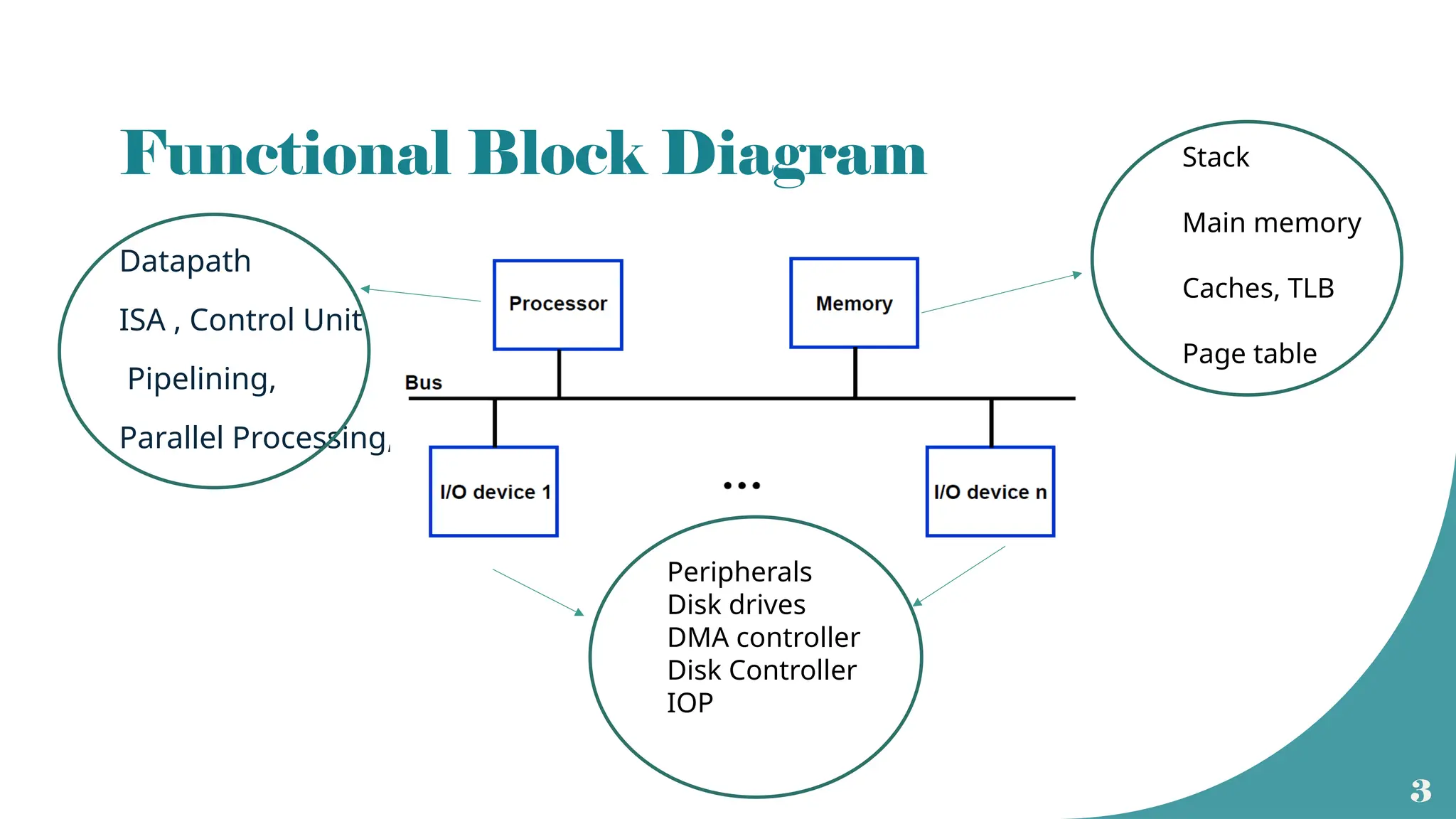
Functional Block Diagram
Datapath
ISA, Control Unit
Pipelining,
Parallel Processing,
Stack
Main memory
Caches, TLB
Page table
Peripherals
Disk drives
DMA controller
Disk Controller
IOP
4.
4
I/O Data transfertechniques
• Program Controlled I/O (Device polling)
• Special instructions to initiate the data transfer between processor and I/O
• Interrupt Driven I/O
• When I/O device is ready , it will interrupt the main program and an interrupt
service routine will be executed
• Hardware Controlled I/O
• There will be a special hardware called Direct Memory Access (DMA) controller to
handle the data transfer
• This is also called DMA transfer
5.
5
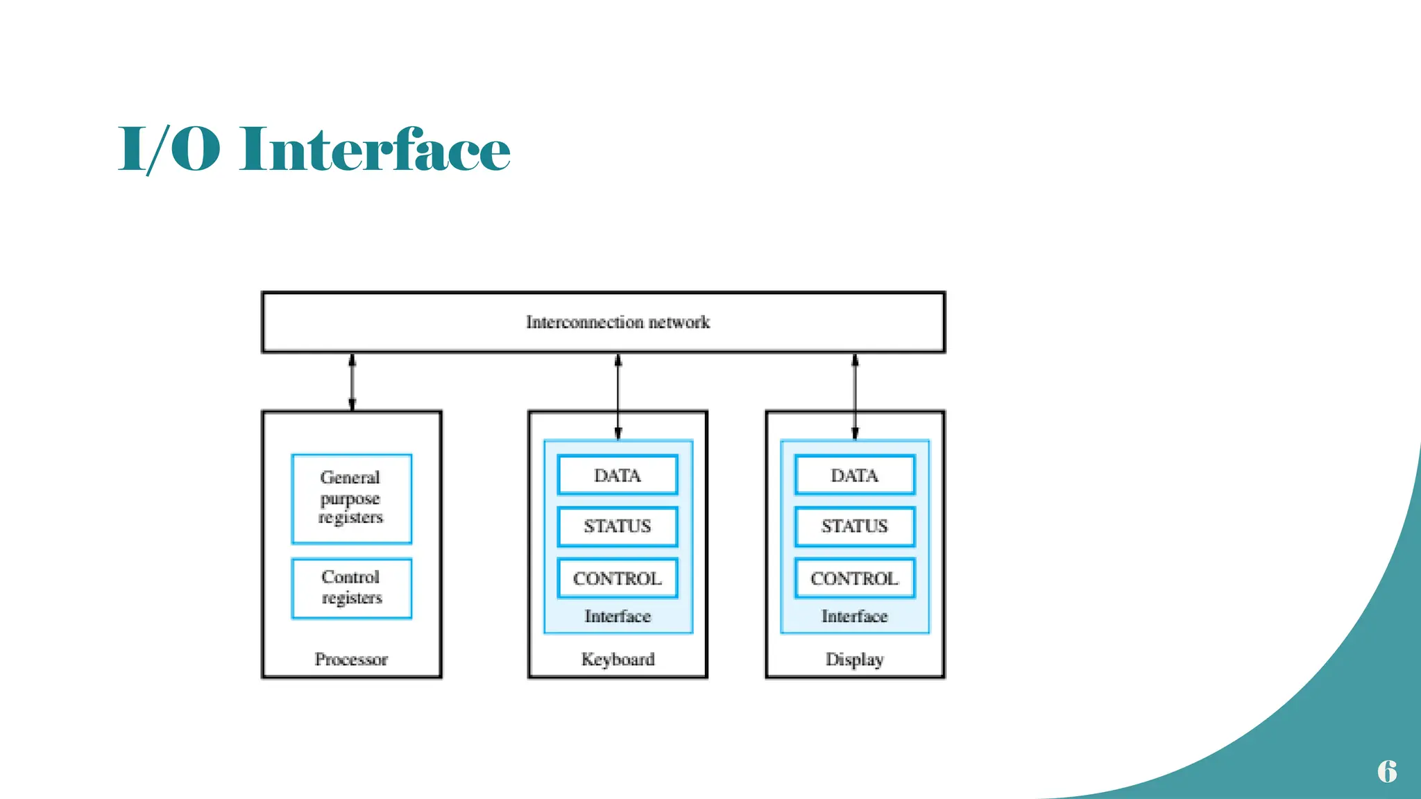
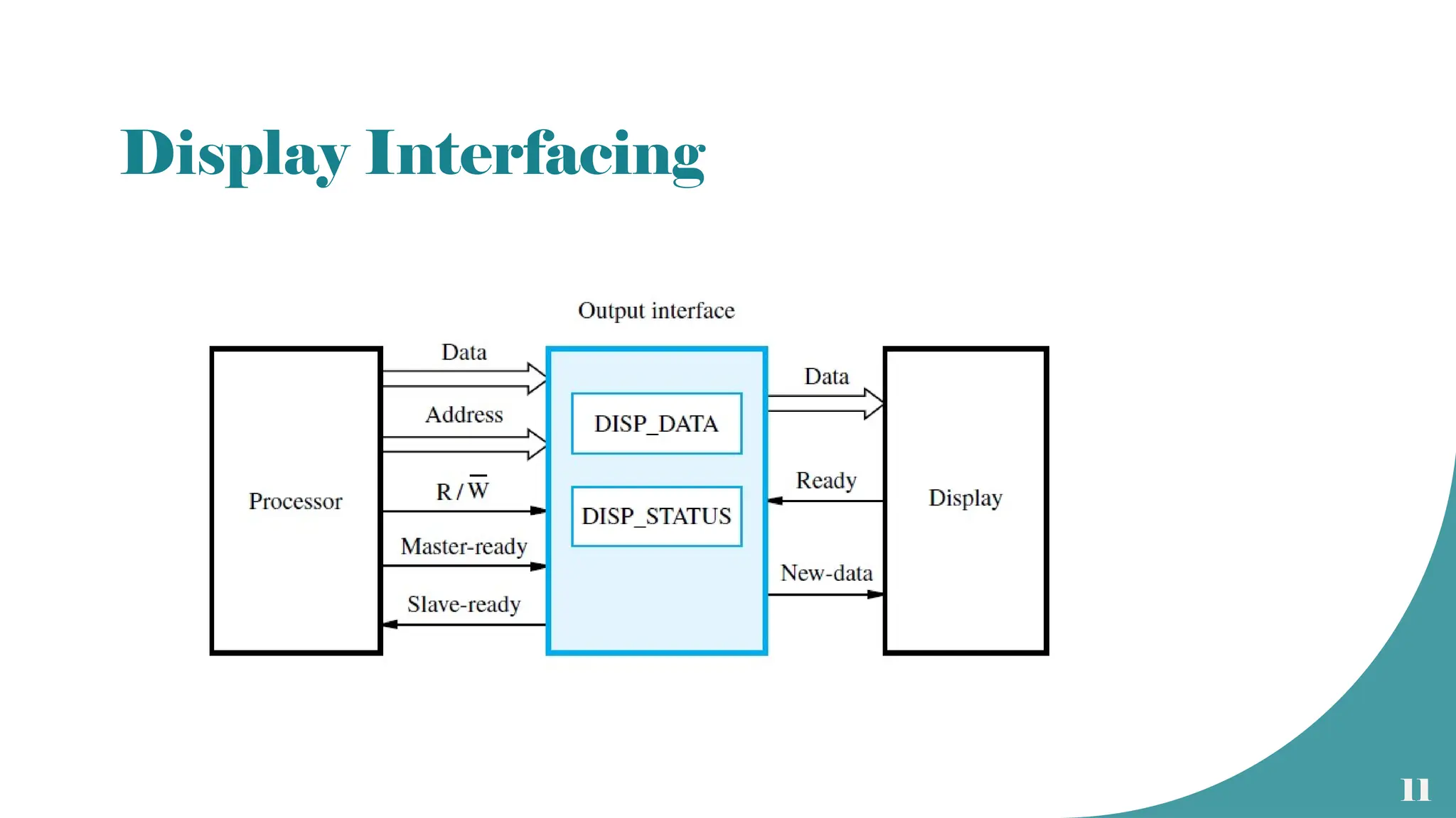
I/O interface
• Circuitryhelps to transfer data between CPU and the peripherals.
• Interfacing side of the peripheral will have a data register called port.
• Can be parallel or serial.
• Interfacing unit will mainly consists of
• Status register
• Control register and timing circuits
• Temporary data register (port)
• Address decoder
• Format conversion circuits
10
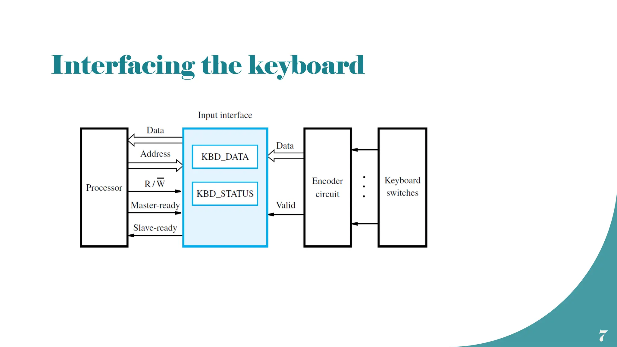
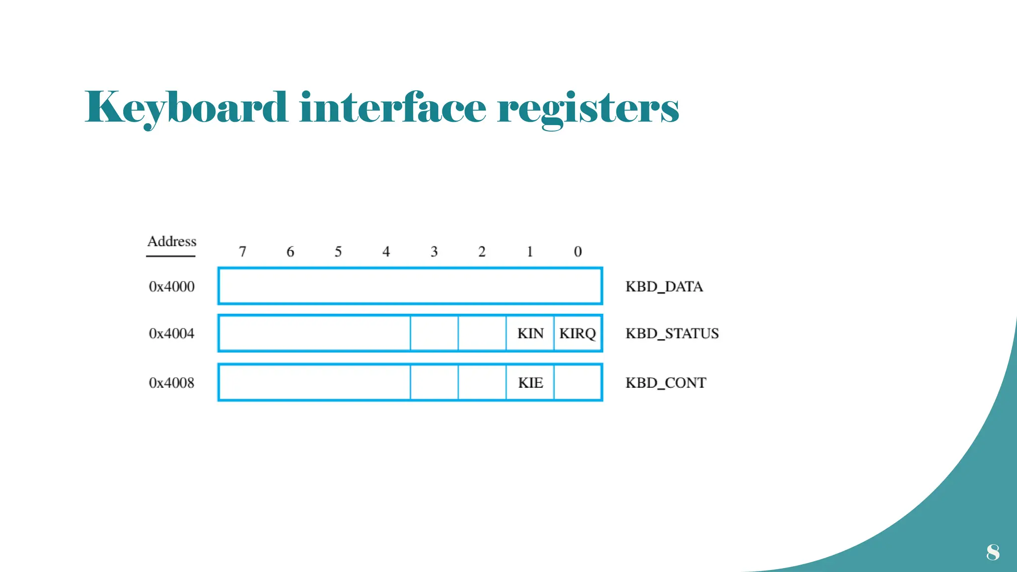
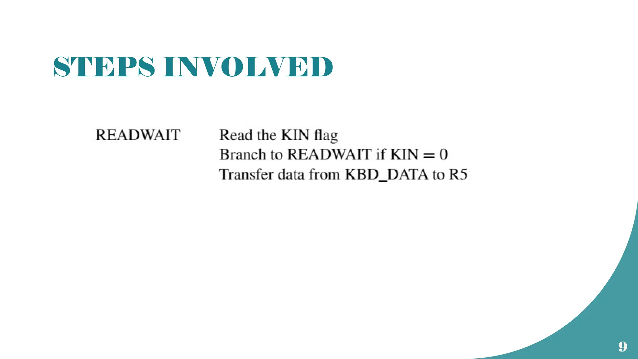
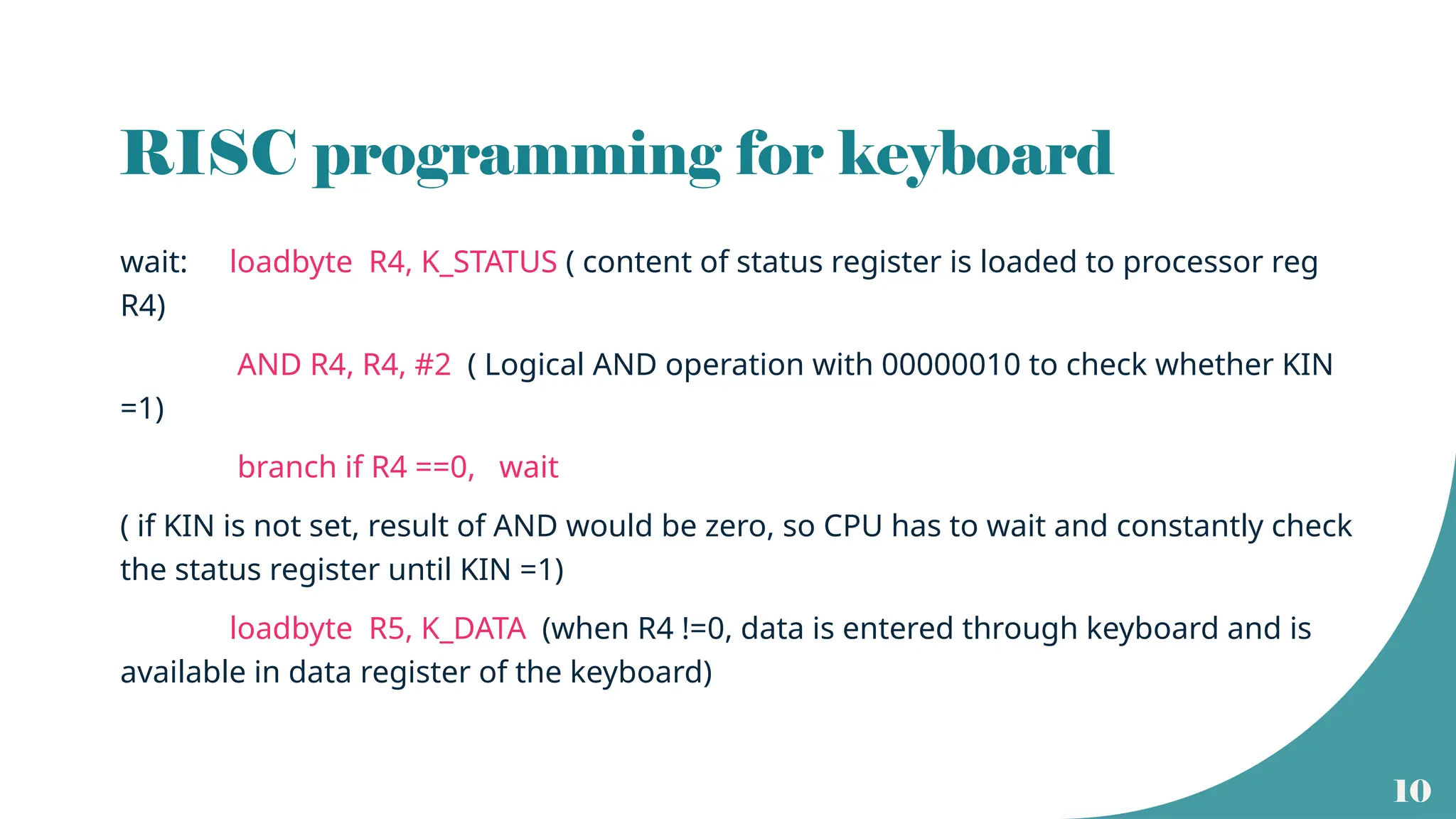
RISC programming forkeyboard
wait: loadbyte R4, K_STATUS ( content of status register is loaded to processor reg
R4)
AND R4, R4, #2 ( Logical AND operation with 00000010 to check whether KIN
=1)
branch if R4 ==0, wait
( if KIN is not set, result of AND would be zero, so CPU has to wait and constantly check
the status register until KIN =1)
loadbyte R5, K_DATA (when R4 !=0, data is entered through keyboard and is
available in data register of the keyboard)
14
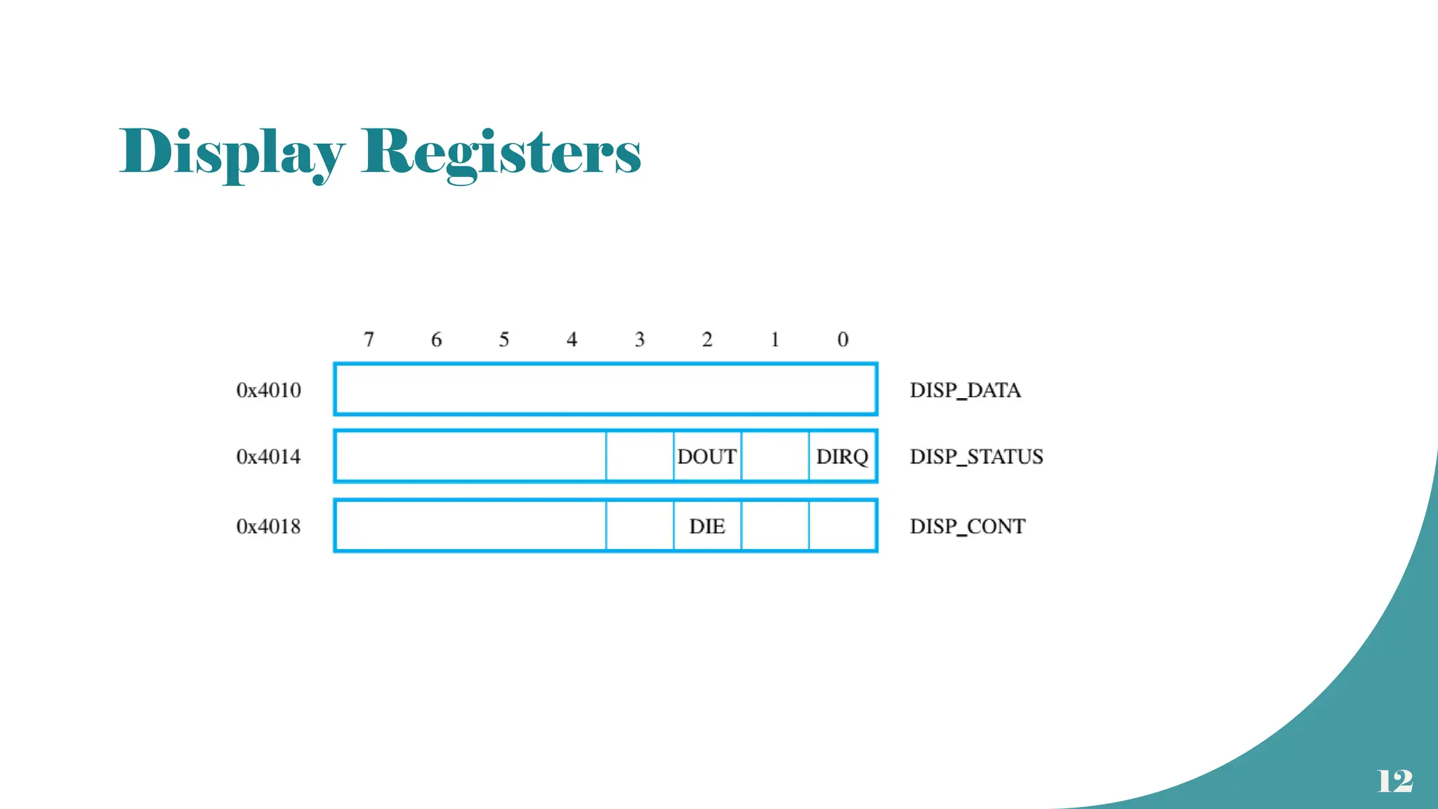
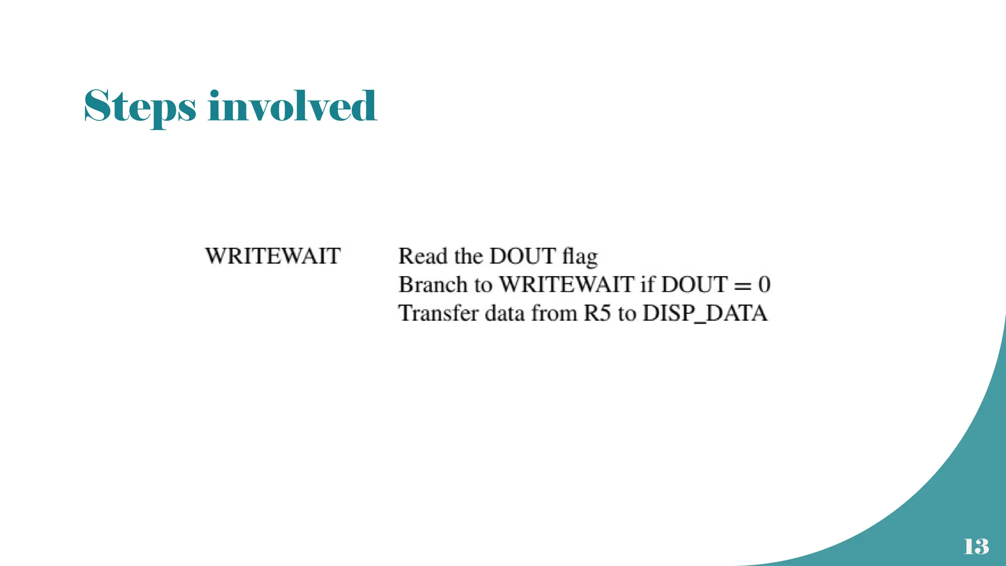
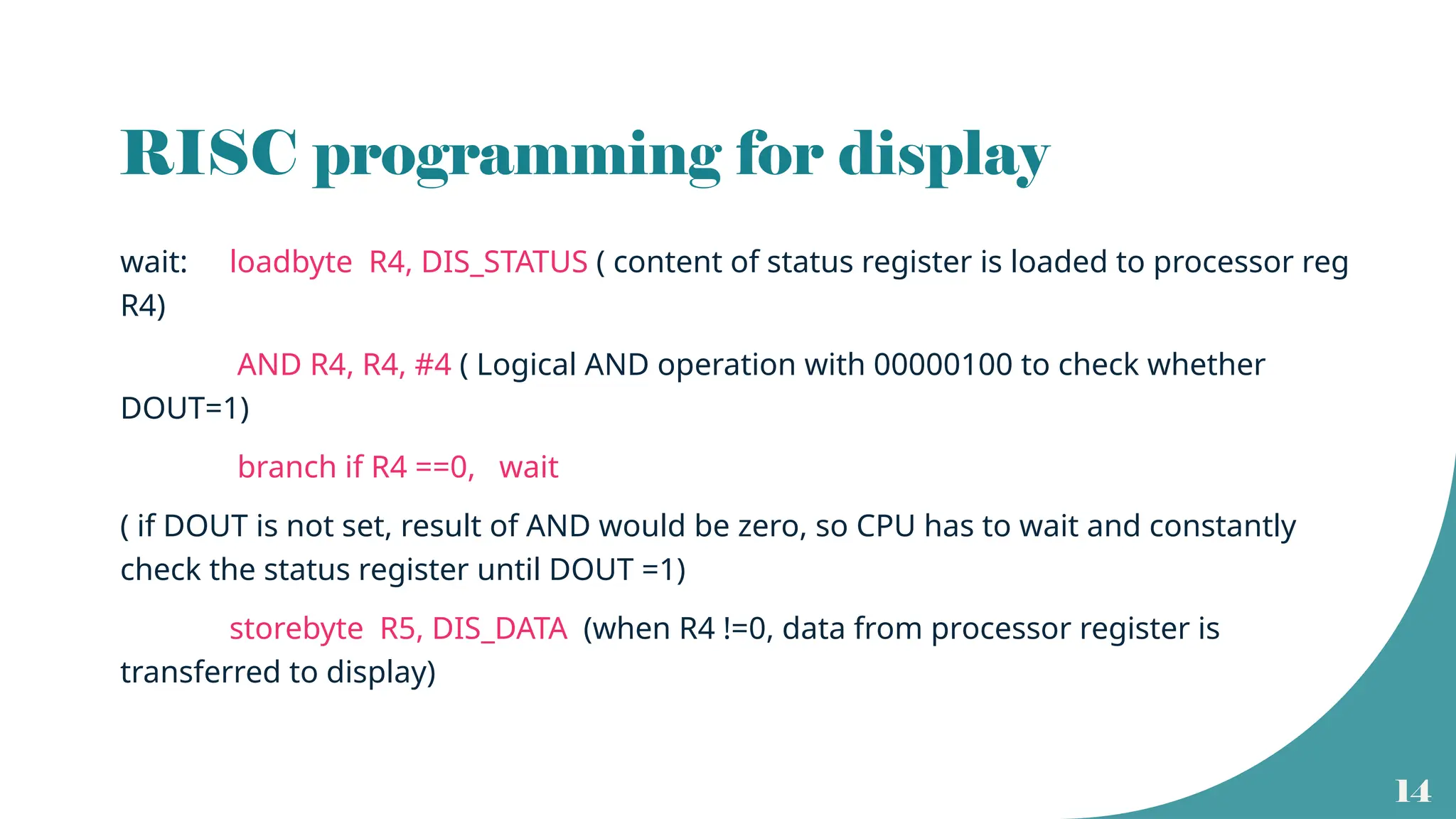
RISC programming fordisplay
wait: loadbyte R4, DIS_STATUS ( content of status register is loaded to processor reg
R4)
AND R4, R4, #4 ( Logical AND operation with 00000100 to check whether
DOUT=1)
branch if R4 ==0, wait
( if DOUT is not set, result of AND would be zero, so CPU has to wait and constantly
check the status register until DOUT =1)
storebyte R5, DIS_DATA (when R4 !=0, data from processor register is
transferred to display)
15.
15
Interrupt driven I/O
•In device polling, CPU has to check for the peripheral to be ready.
• Wastage of CPU time.
• Alternative method is to let the CPU to go ahead with its normal operations and
inform the CPU when the peripheral is ready.
• A hardware control signal is sent by the peripheral to the CPU to alert the processor
• It is called an interrupt request since it interrupts the CPU operations.
• Upon receiving the interrupt request, CPU will stop the ongoing task and will take
care of the interrupt.
• The I/O operation is handled as a subroutine call.
16.
16
Interrupts
• Interrupt isa signal that invites the attention of the processor to suspend its current
program.
• In response to the interrupt, CPU will stop the execution of the running program and will
service the interrupt.
• Can be of two types
• Hardware interrupts – signals generated by the peripherals directly.
- also called device driver
• Software – signals generated by system software due to some temporary errors or exceptions
- software interrupts can happen during instruction execution
- also called trap
17.
17
Maskable and nonmaskable
• Hardware interrupts can be of two types
• Maskable interrupt : If the service to an interrupt can be delayed or ignored
due to the priority of the user program, it s a maskable interrupt.
• Non maskable interrupt: If the interrupt is of higher priority and if it cannot be
delayed or ignored, it is a non maskable interrupt.
• The priority of the interrupt is checked during interrupt cycle
19
Interrupt cycle
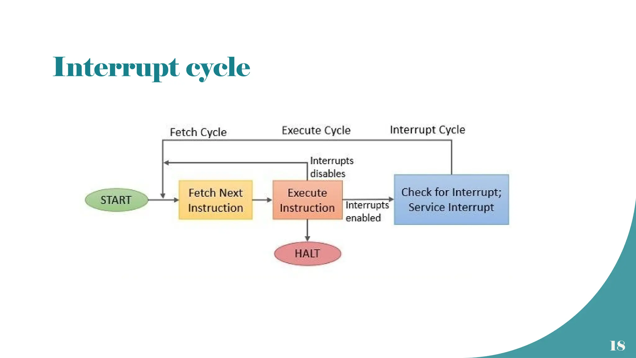
• Atthe end of execution of each instruction, CPU will check for pending
interrupts.
• If a non maskable interrupt request is present, CPU will suspend its current
program
and will service the interrupt.
• If the interrupt is maskable, CPU will resume its current program.
• Servicing the interrupt can be considered as a special cycle called interrupt
cycle.
• At the end of interrupt cycle, execution of the next instruction resumes
20.
20
Interrupt Service Routine(ISR)
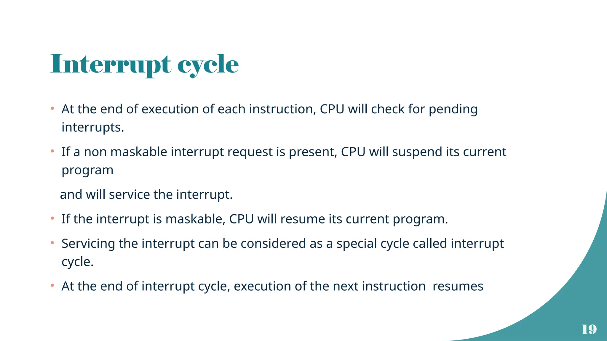
• Peripheral will send an interrupt request
• CPU will complete the execution of
current instruction. ( instruction ‘i’)
• After the execution completion,
Program counter will be loaded with
the staring address of ISR.
• The main program is now interrupted
(stopped) and will be resumed upon
completion of ISR
21.
21
ISR and mainprogram
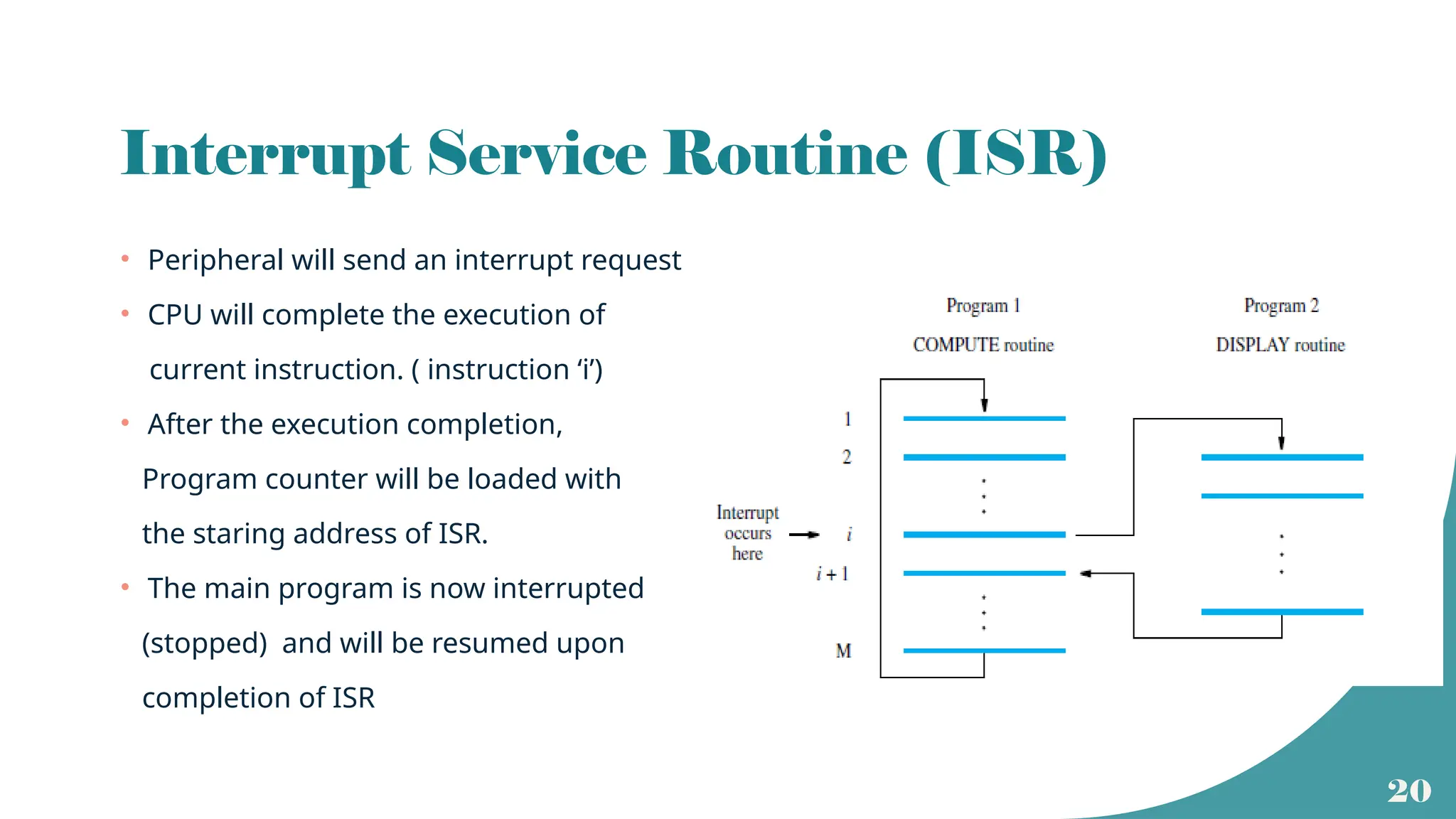
• The starting address of the ISR should be loaded to program counter separately
• Before the execution of ISR, CPU has to keep the important details
related to its main program.
• Address of (i+1)th instruction should be saved in PCtemp and then
to some known location.
• Content of the status register should be moved to the stack.
• This will help to resume the main program unaltered
upon the termination of ISR
• Last instruction of ISR will be a return instruction that places
PC temp address back to PC and previous content of the status register
PC
ISR
22.
22
Interrupt latency
• Timedelay between the reception of an interrupt request signal and the
beginning of ISR execution is termed as interrupt latency.
• Latency occurs due to
• Memory operations involved to store the next instruction address and the status
register contents.
• Memory operations involved in loading PC with starting address of ISR.
23.
23
Design issues
• Identificationof the device that raised the interrupt
• Identification of the type of interrupt to be serviced.
• Managing the newly raised interrupt at the time of servicing an already raised
interrupt
• Handling of interrupts raised by multiple peripherals simultaneously
24.
24
Priority Interrupts
• Whenmultiple I/O devices are present
• Different peripherals may send interrupts simultaneously
• Priority level for each type of interrupt is assigned.
• Different interrupts will have different ISR.
• Starting address of each ISR is placed on an interrupt vector table.
• A peripheral will send an interrupt request that will point to the starting address of the
corresponding ISR.
• CPU uses a program to identify the priority level of current user program and the
interrupt.
25.
25
Enabling and disablingof interrupts
• When an interrupt request is raised, interrupt enable bit of the peripheral is set.
• This will be reset upon successful completion of the ISR.
• There will be a separate instruction at the end of ISR to update the status and
control register of the peripheral.
26.
26
Revisiting Virtual
Memory
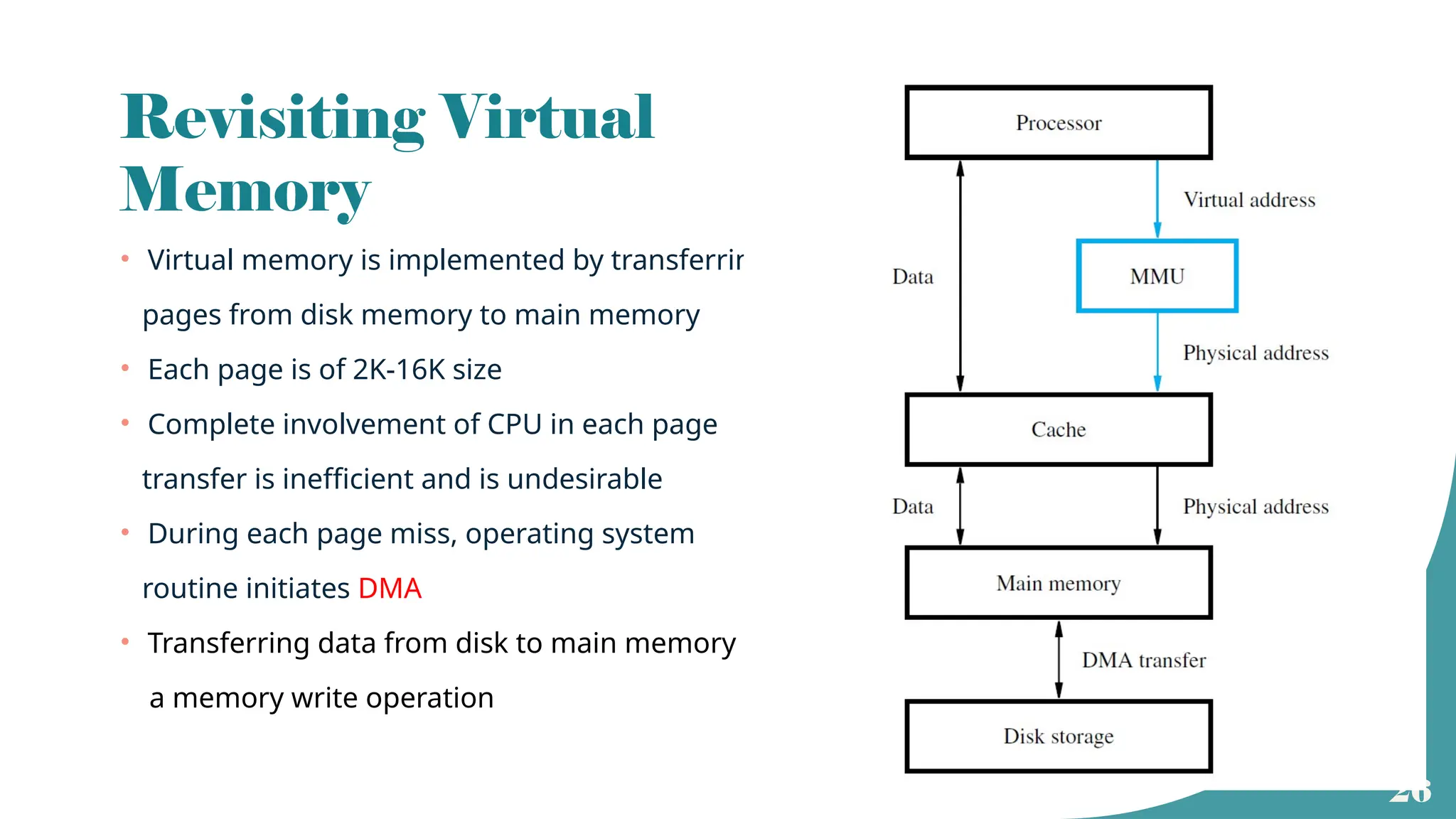
• Virtualmemory is implemented by transferring
pages from disk memory to main memory
• Each page is of 2K-16K size
• Complete involvement of CPU in each page
transfer is inefficient and is undesirable
• During each page miss, operating system
routine initiates DMA
• Transferring data from disk to main memory is
a memory write operation
27.
27
DMA and DMAController
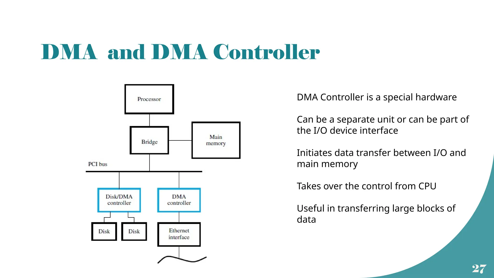
DMA Controller is a special hardware
Can be a separate unit or can be part of
the I/O device interface
Initiates data transfer between I/O and
main memory
Takes over the control from CPU
Useful in transferring large blocks of
data
28.
28
DMA transfer betweendisk and main memory
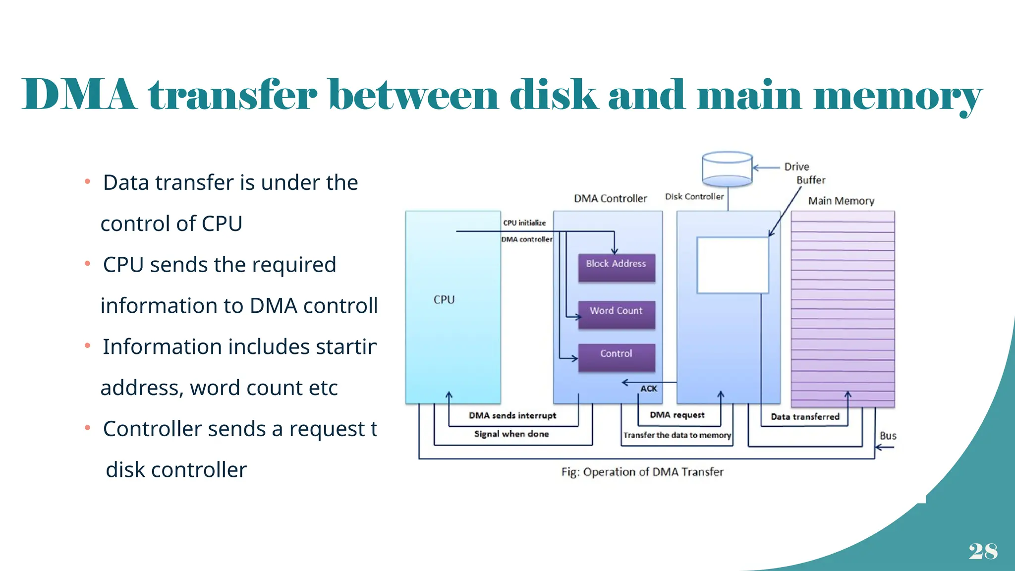
• Data transfer is under the
control of CPU
• CPU sends the required
information to DMA controller
• Information includes starting
address, word count etc
• Controller sends a request to
disk controller
29.
29
Read/ Write operation
•Memory read operation using DMA takes place at the time of replacement of a modified page or at
the time of transferring a block of data to an output device.
• More common is writing into main memory from disk ( external or internal).
• Before memory write, data residing in disk will be transferred to a buffer in the disk drive controller.
• This process is initiated by the operating system.
• Once data is in the buffer, CPU sends the necessary details to DMA.
• DMA takes over the control of system bus.( Bus Request and Bus Grant signals)
• Data from buffer will be transferred to the specified location in main memory.
• Once the writing operation is complete ( word count ==0), DMAC sends an interrupt to CPU.
• CPU takes the control of system bus
30.
30
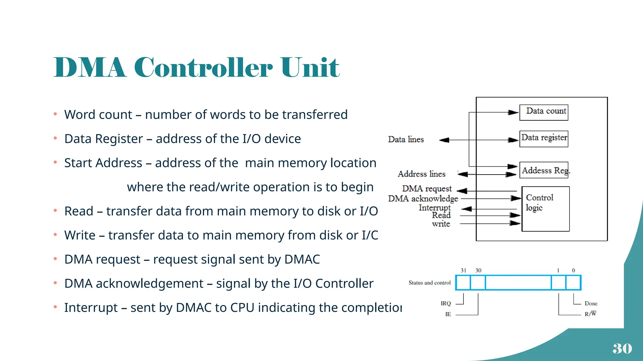
DMA Controller Unit
•Word count – number of words to be transferred
• Data Register – address of the I/O device
• Start Address – address of the main memory location
where the read/write operation is to begin
• Read – transfer data from main memory to disk or I/O
• Write – transfer data to main memory from disk or I/O
• DMA request – request signal sent by DMAC
• DMA acknowledgement – signal by the I/O Controller
• Interrupt – sent by DMAC to CPU indicating the completion
31.
31
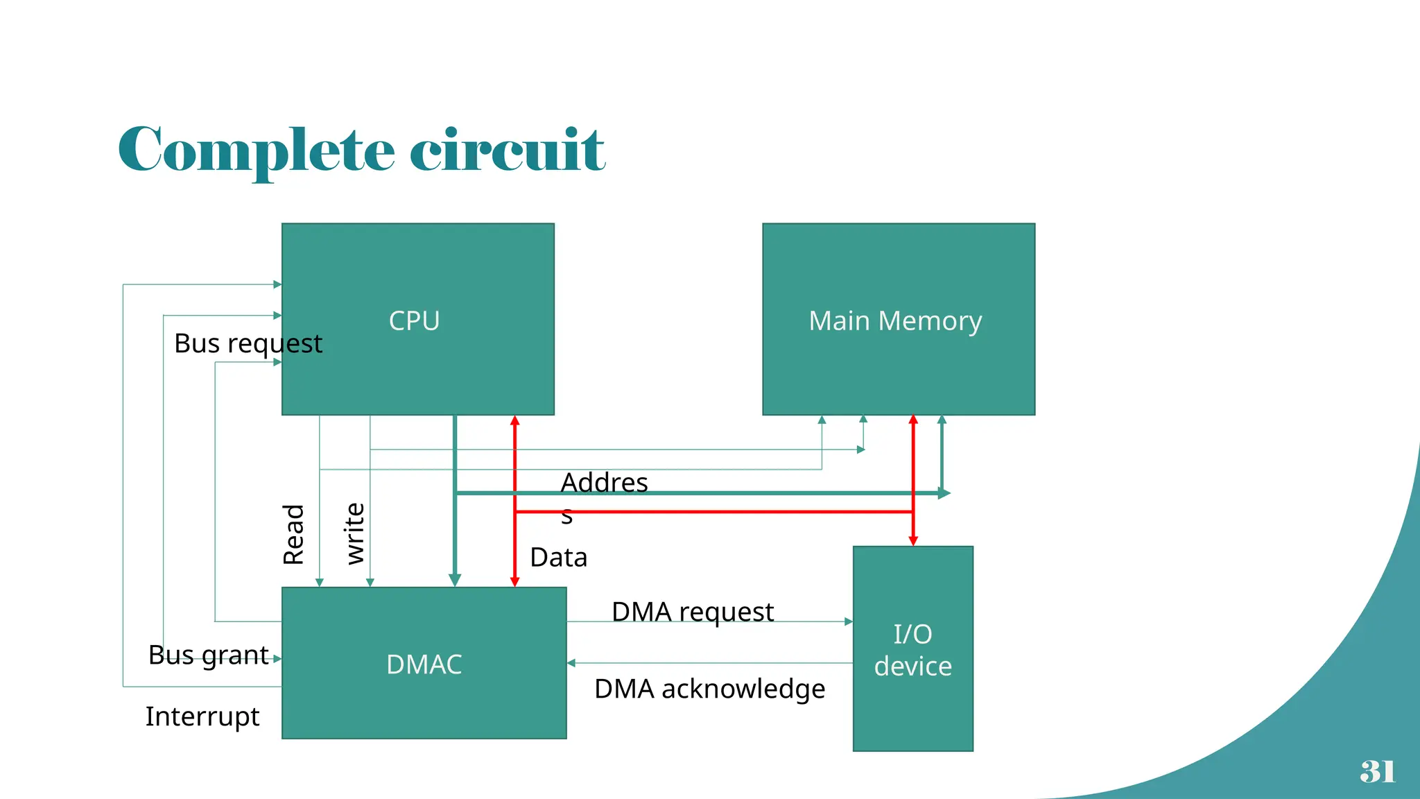
Complete circuit
CPU MainMemory
DMAC
I/O
device
Interrupt
Bus grant
Bus request
Addres
s
Data
Read
write
DMA request
DMA acknowledge
32.
32
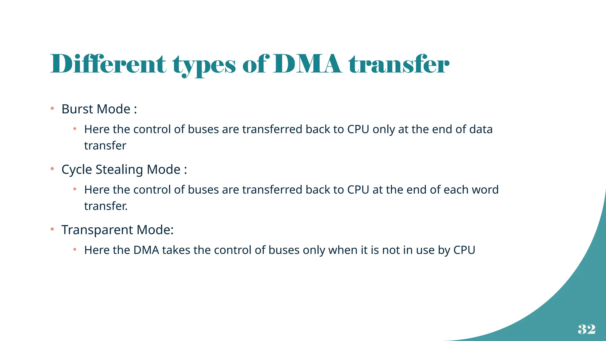
Different types ofDMA transfer
• Burst Mode :
• Here the control of buses are transferred back to CPU only at the end of data
transfer
• Cycle Stealing Mode :
• Here the control of buses are transferred back to CPU at the end of each word
transfer.
• Transparent Mode:
• Here the DMA takes the control of buses only when it is not in use by CPU
33.
33
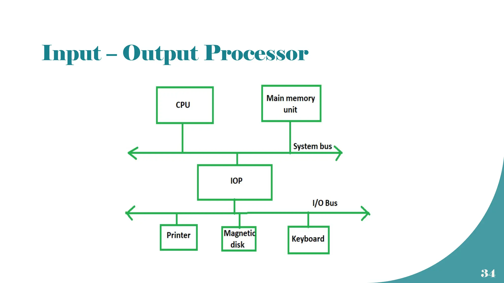
Input Output Processor(IOP)
• DMAC works as per the instructions given by CPU
• It does not have any instructions within it.
• To speed up the data processing of I/O devices without using CPU, special
processors called IOP can be used.
• IOP is similar to CPU but takes care of only I/O processing.
• Unlike DMAC, it can fetch and execute its own instructions.
• IOP also has DMA capability
35
Working
• Communication betweenIOP and peripherals is similar to the program control
method of transfer
• In computers with CPU and IOP , CPU is the master and IOP is the slave
• CPU initiates all operations but IOP executes the I/O instructions.
• Instructions read from memory by IOP are called commands
• Commands are written by experienced programmers.
• CPU informs the IOP regarding the location of commands.
36.
36
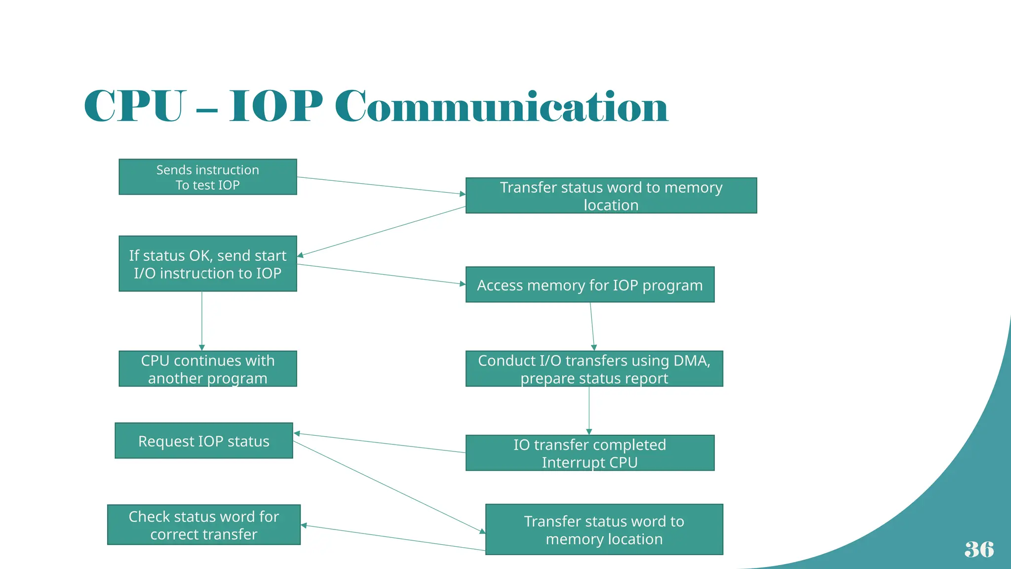
CPU – IOPCommunication
Sends instruction
To test IOP Transfer status word to memory
location
If status OK, send start
I/O instruction to IOP
Access memory for IOP program
CPU continues with
another program
Conduct I/O transfers using DMA,
prepare status report
IO transfer completed
Interrupt CPU
Request IOP status
Transfer status word to
memory location
Check status word for
correct transfer