Downloaded 742 times
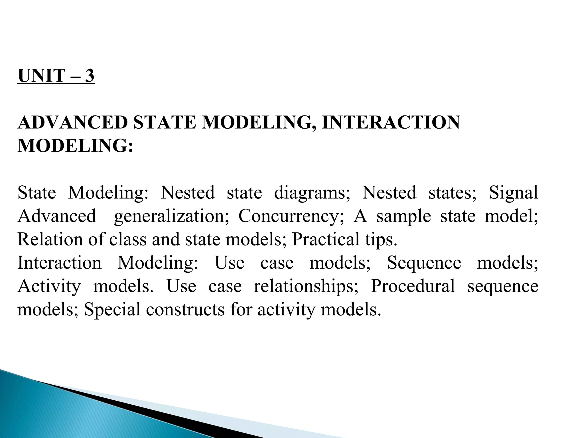
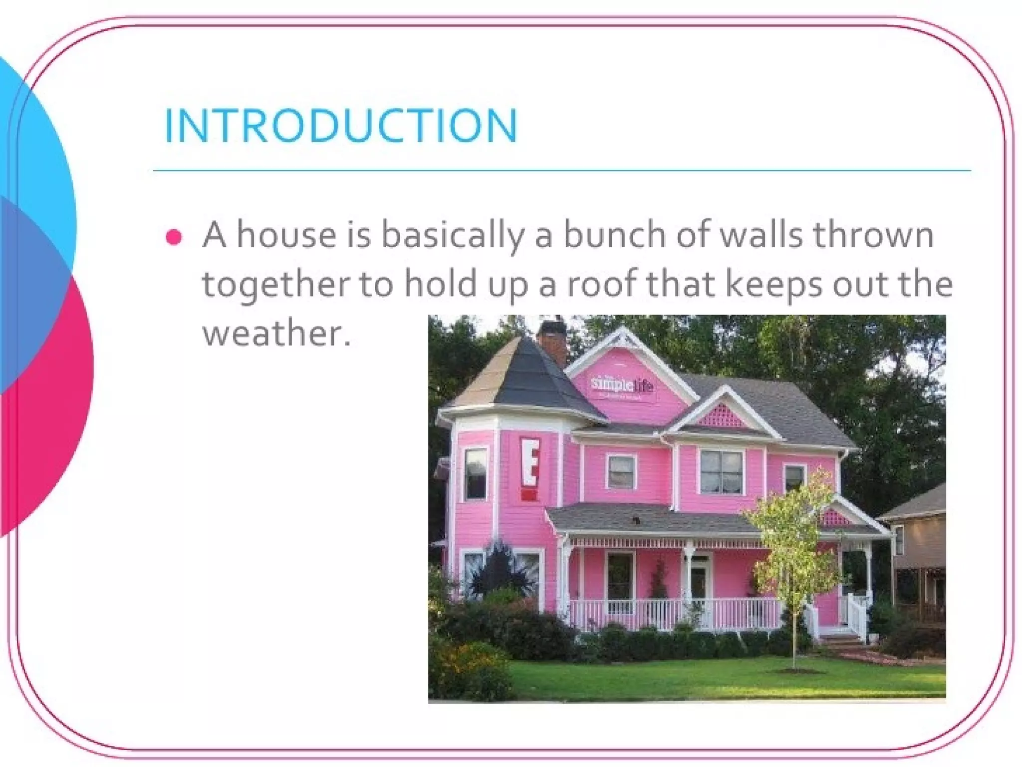
![Idle
off hook / play dial tone
[valid subscriber] Active
on hook
PlayingDialTone
digit digit
connected
complete
Talking
Dialing Connecting](https://image.slidesharecdn.com/unit-3advancedstatemodelinginteractionmeodelling-140929182830-phpapp02/75/Unit-3-advanced-state-modeling-interaction-meodelling-8-2048.jpg)
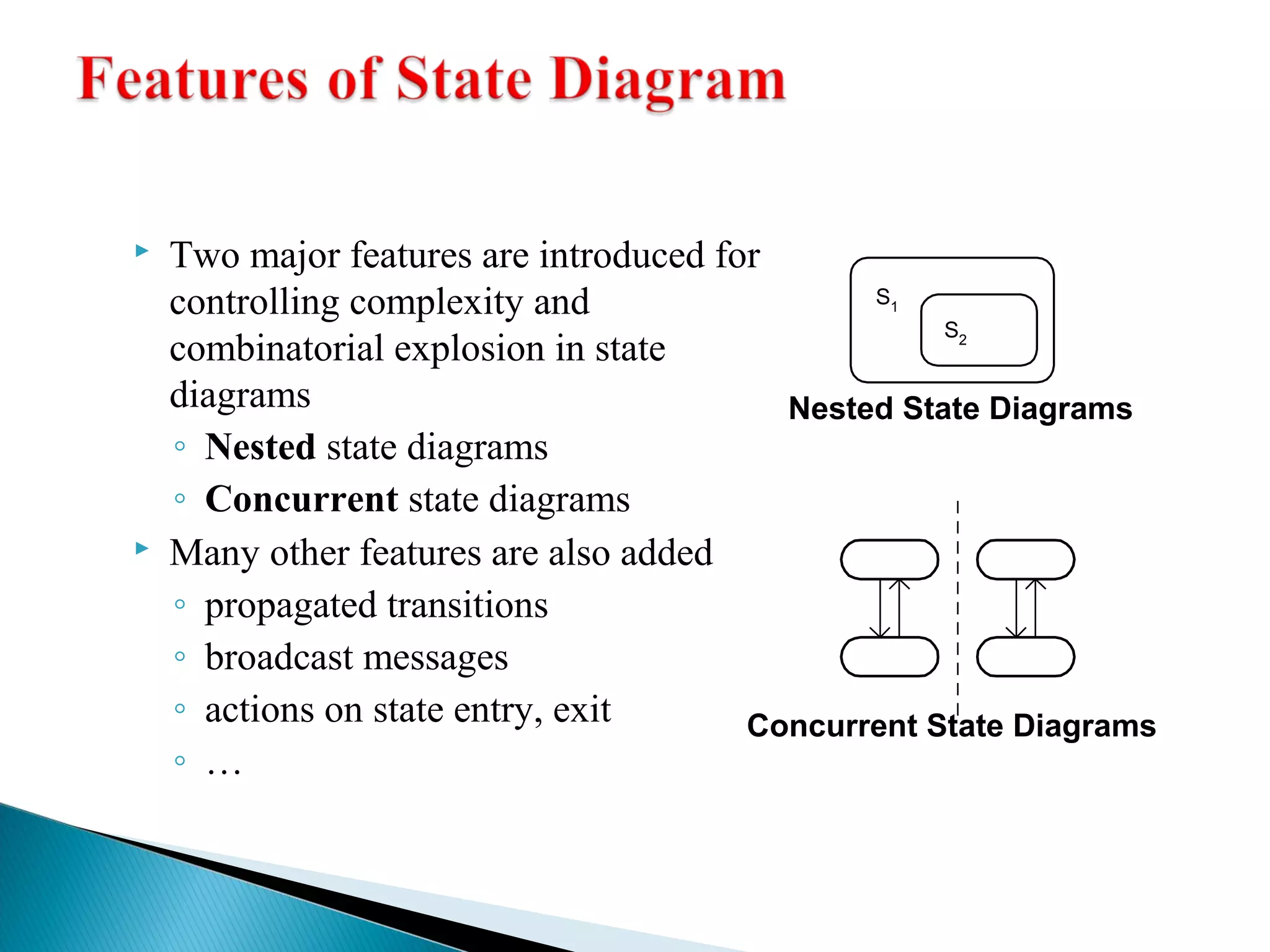
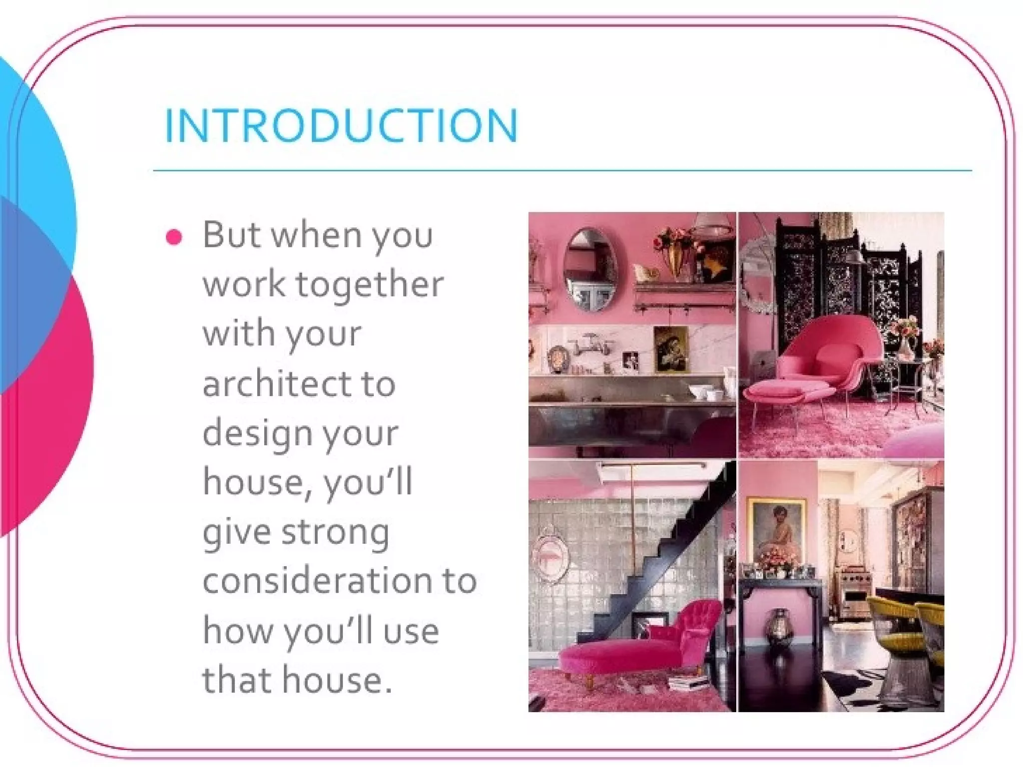
![Simple State
Complex State
Substate1
entry: entry action
event( args )[ cond ] /
action event( args )[ cond ] / ^target.event(args)
action ^target.event(args)
Substate2
event( args )[ cond ] /
action ^target.event(args)
event( args )[ cond ] /
action ^target.event(args)](https://image.slidesharecdn.com/unit-3advancedstatemodelinginteractionmeodelling-140929182830-phpapp02/75/Unit-3-advanced-state-modeling-interaction-meodelling-9-2048.jpg)
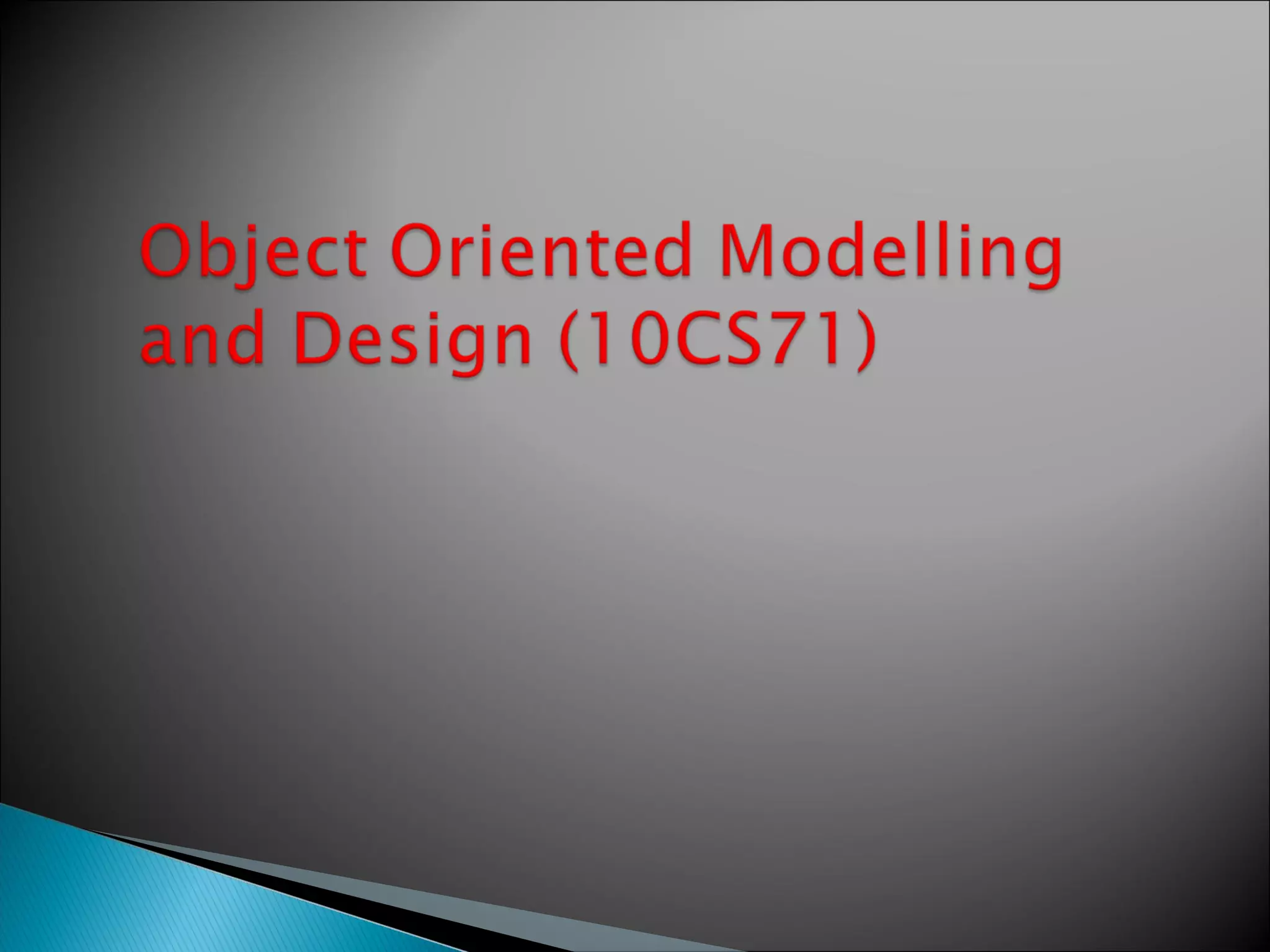
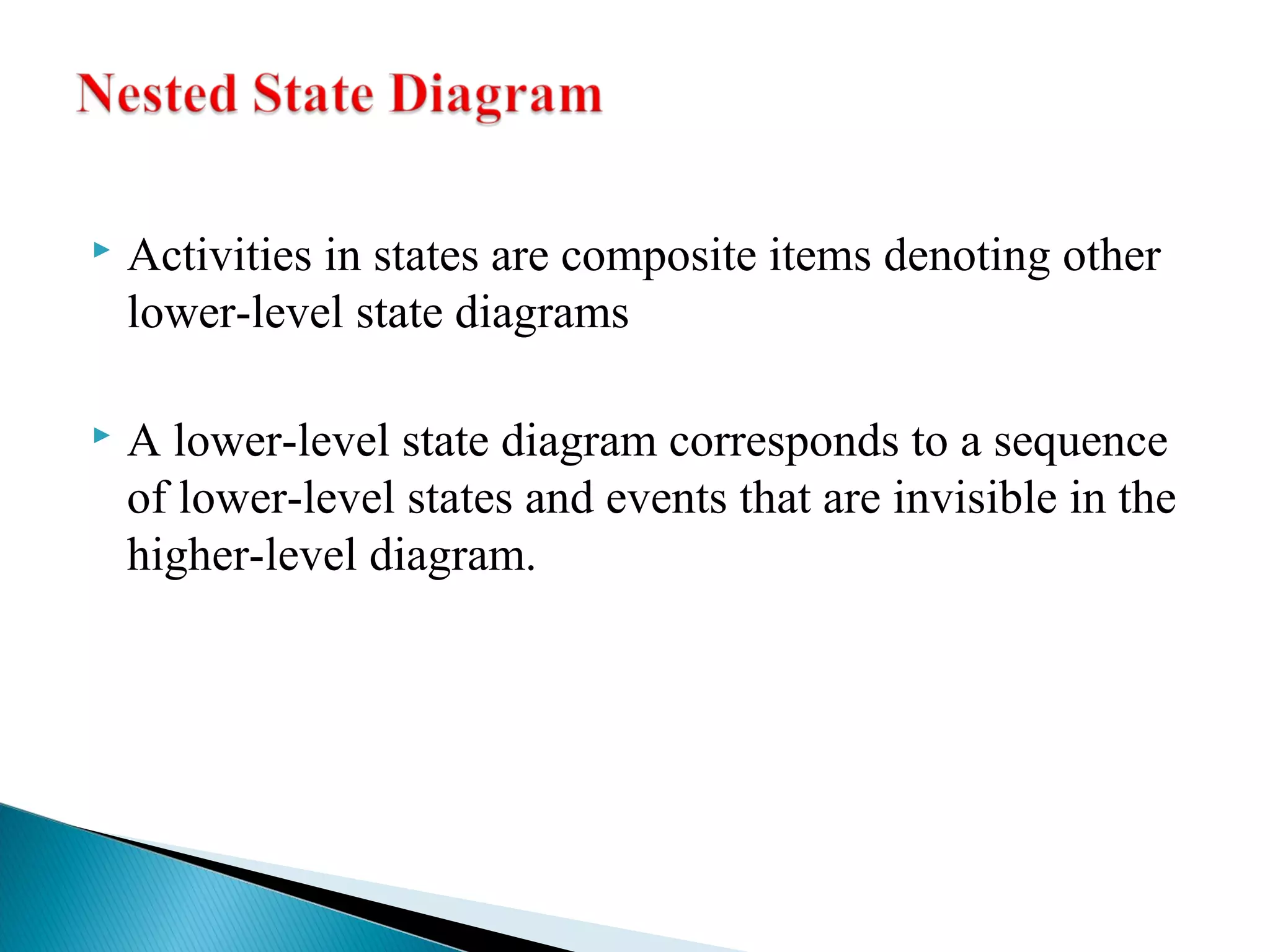
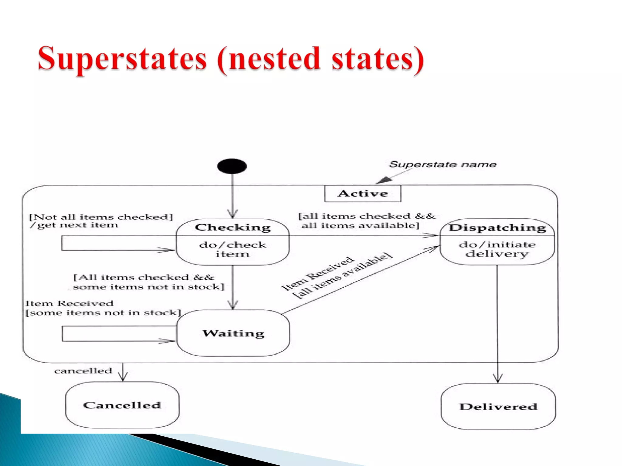
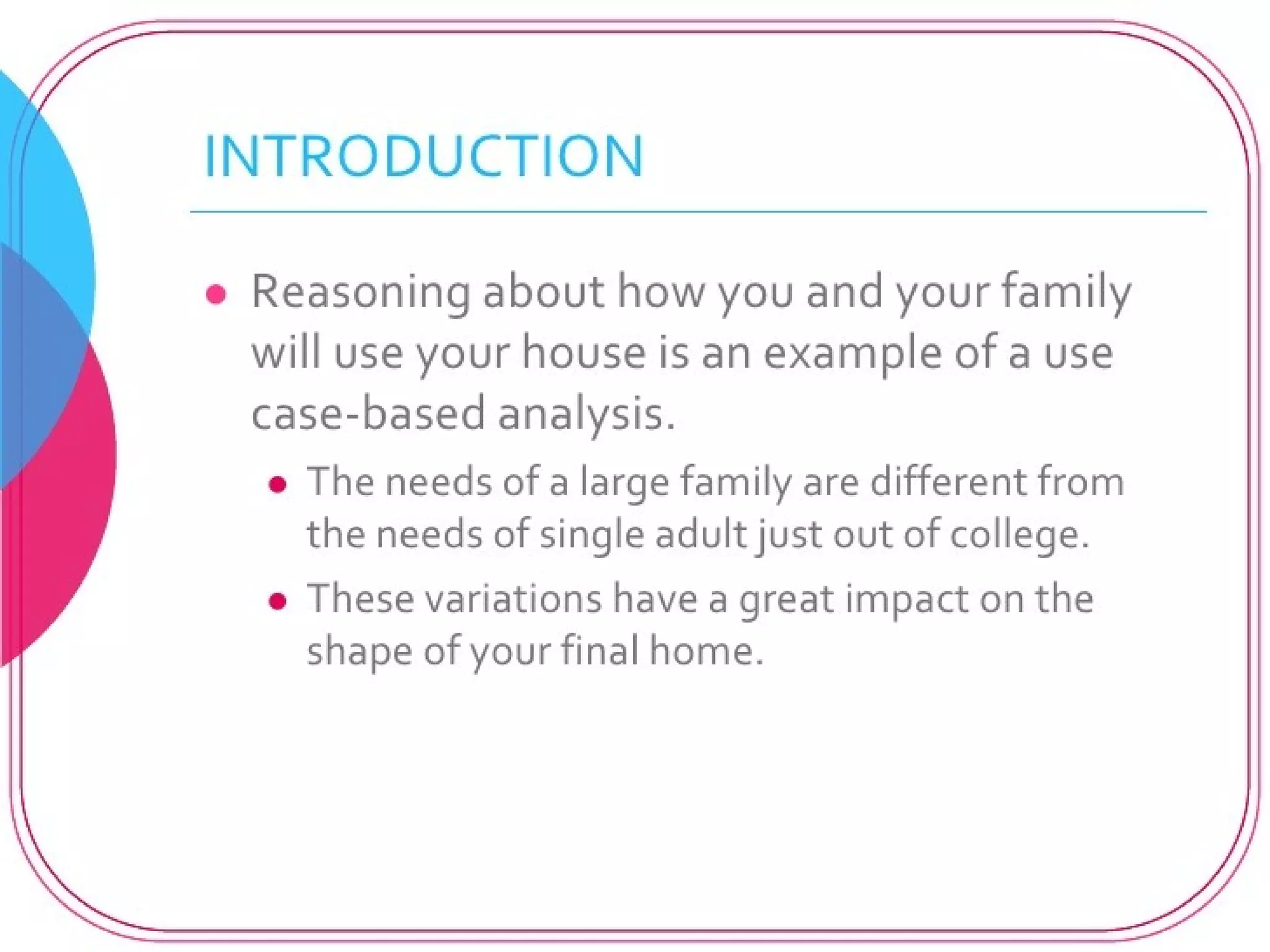
![Checking
do / check
Item
Dispatching
do / initiate
delivery
Delivering
[all items checked &&
some items not in stock]
Order item
[all items checked && all items available]
Dispatch items
[all items available]
Item received
delivery
get first item
Ordering
Exit/ Item received
do / order Item
cancelled Canceling
*[all items checked]
get next item
entry / deliver
Items
do / Remove
Item](https://image.slidesharecdn.com/unit-3advancedstatemodelinginteractionmeodelling-140929182830-phpapp02/75/Unit-3-advanced-state-modeling-interaction-meodelling-11-2048.jpg)
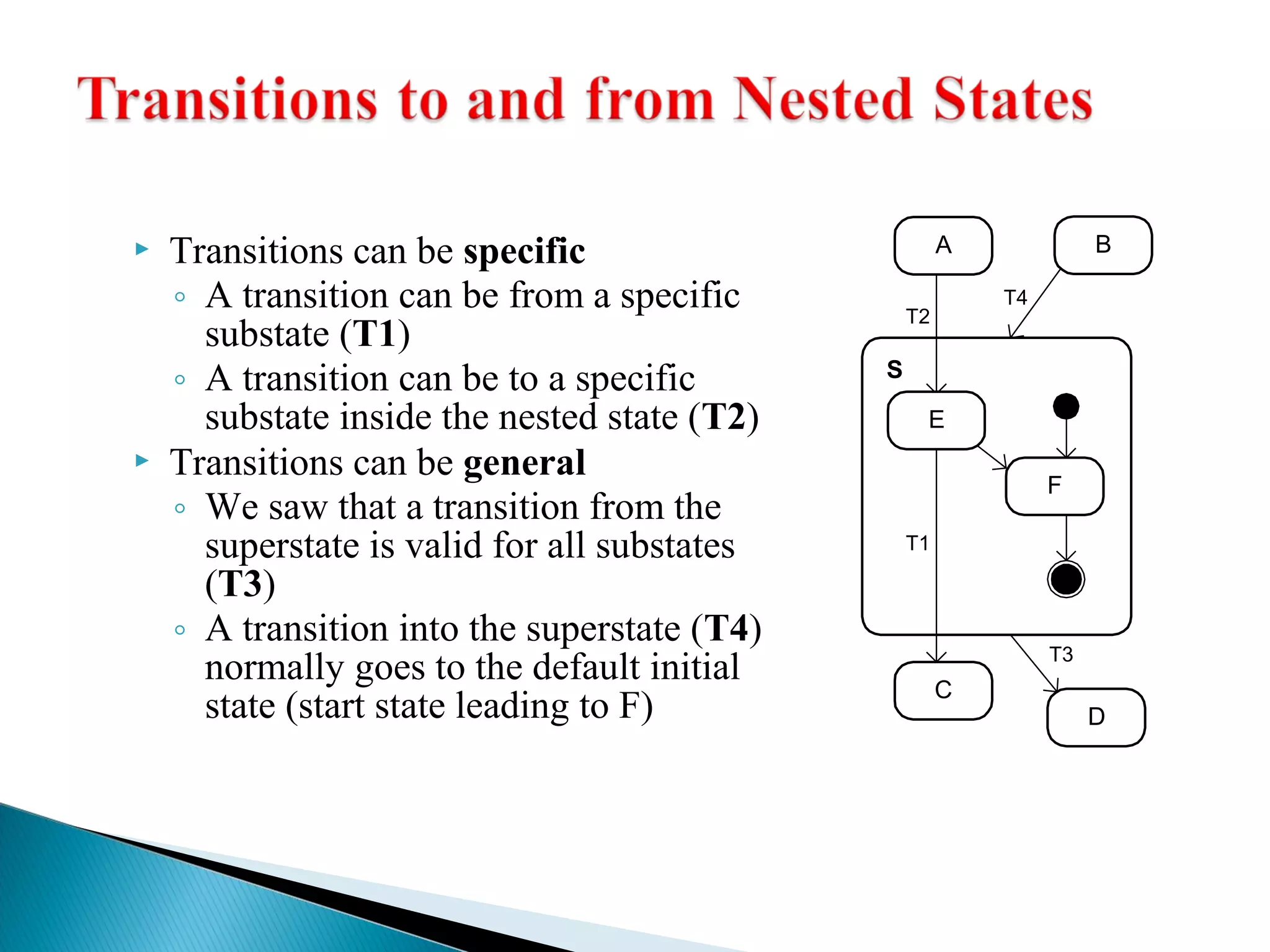
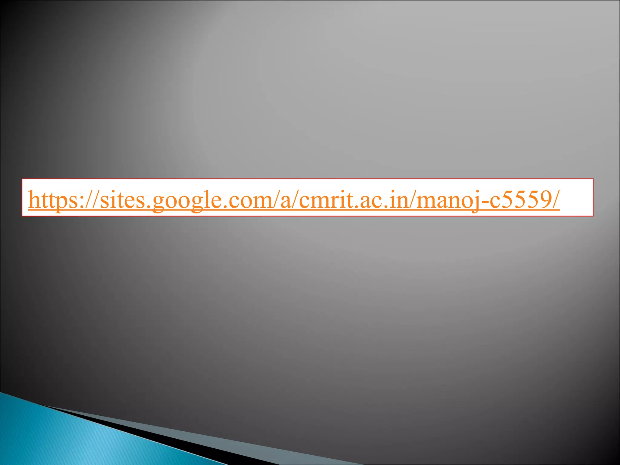
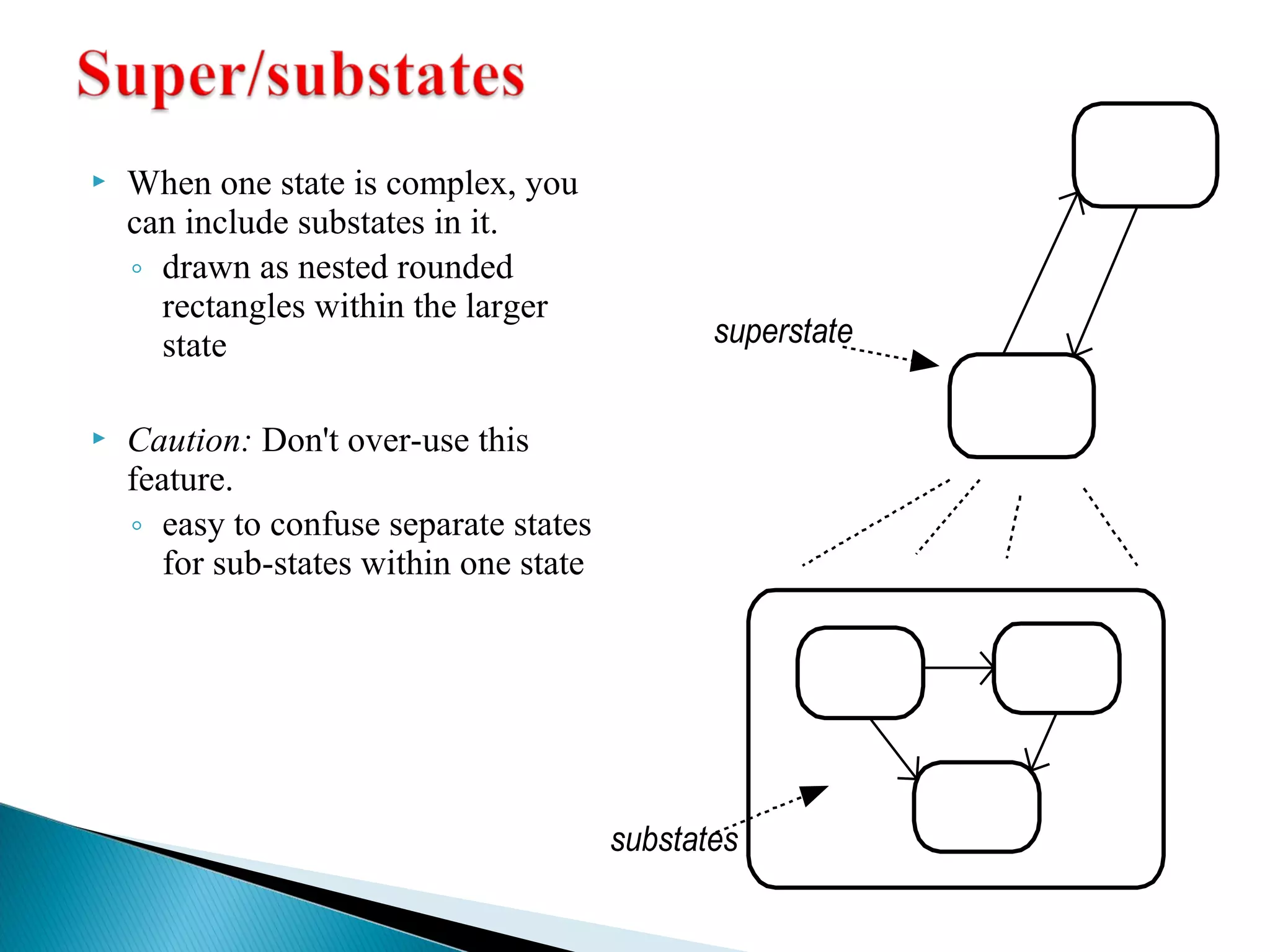
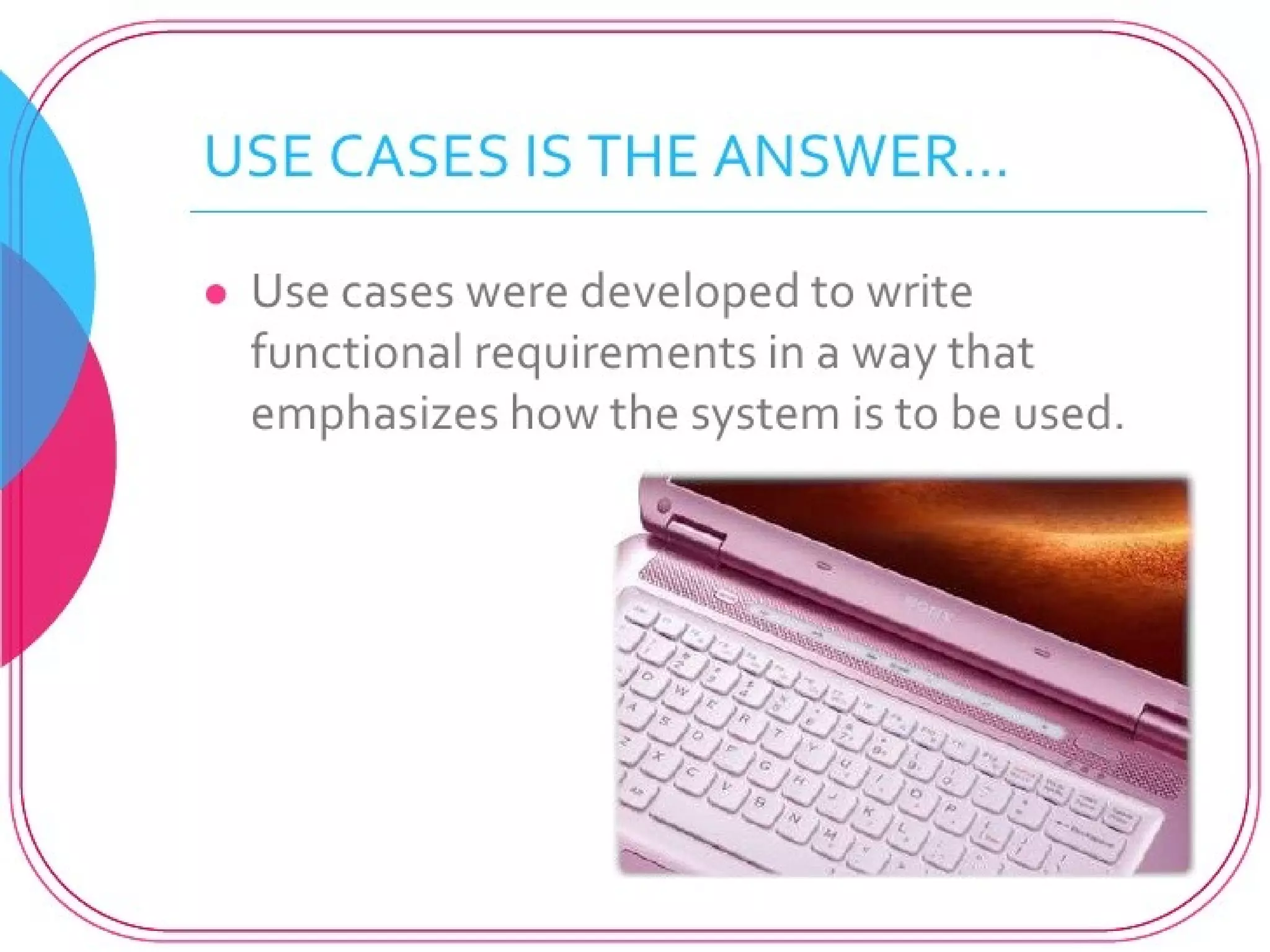
![release key
Ignition turn key to start
[Transmin iNsseiountral]
turn key off
Transmission
Forward
Accelerator
depress accelerator
release accelerator
push R
push N
push N push F
upshift
downshift
upshift
downshift
stop
Brake
depress brake
release brake
Car
off starting on
Neutral Reverse
first second third
off on off on](https://image.slidesharecdn.com/unit-3advancedstatemodelinginteractionmeodelling-140929182830-phpapp02/75/Unit-3-advanced-state-modeling-interaction-meodelling-17-2048.jpg)

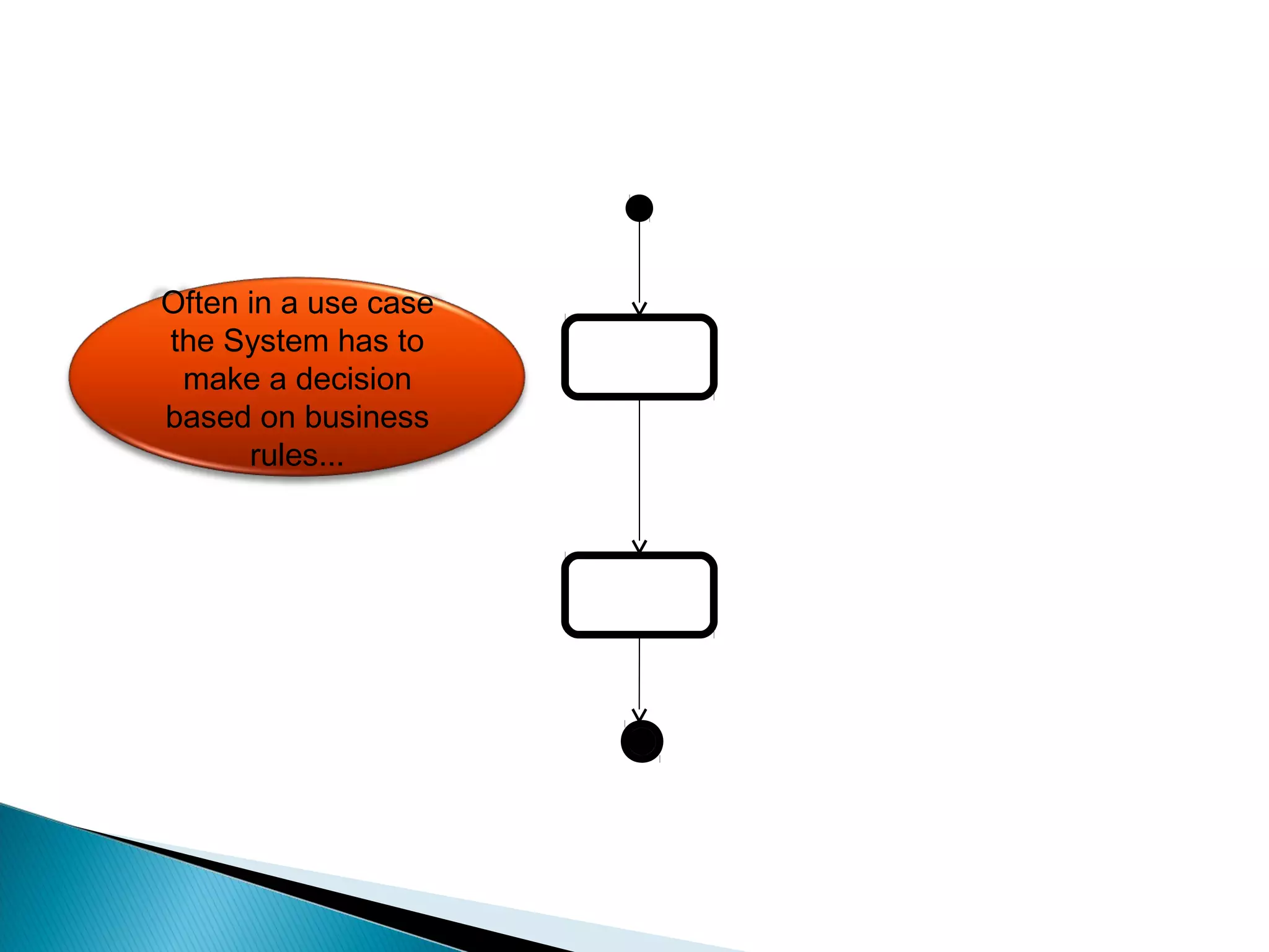
![[Condition]
For each X:
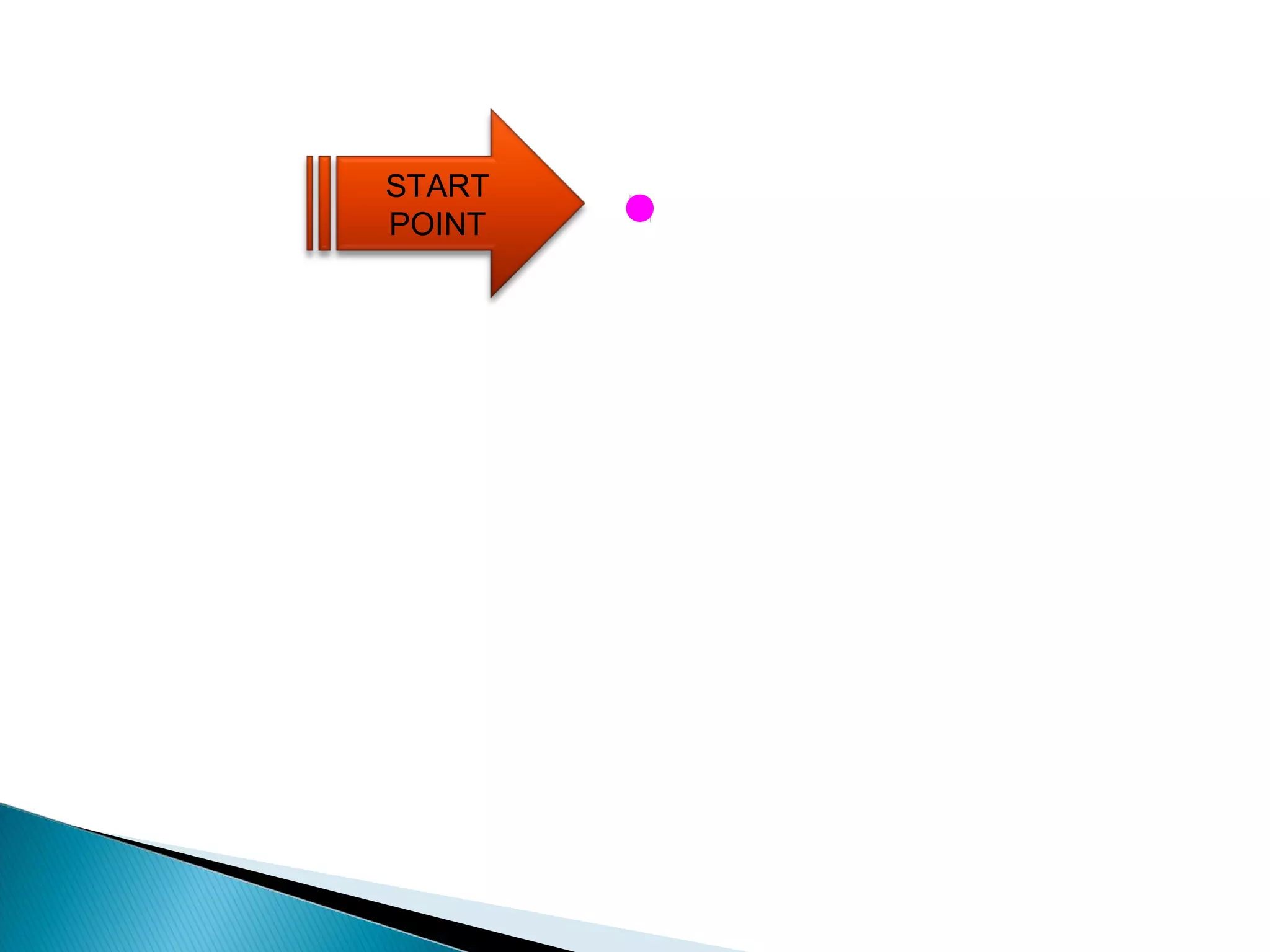
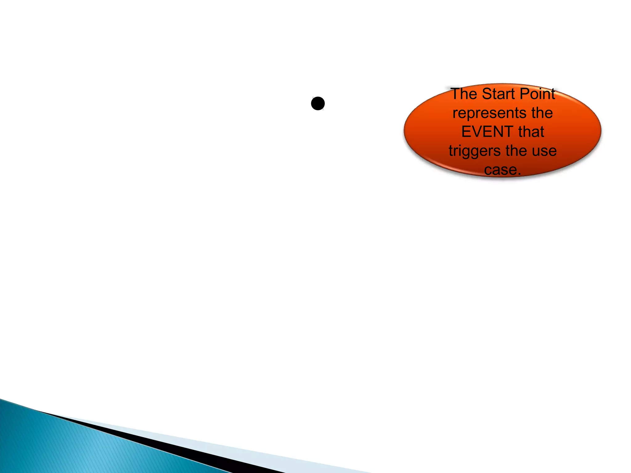
START POINT
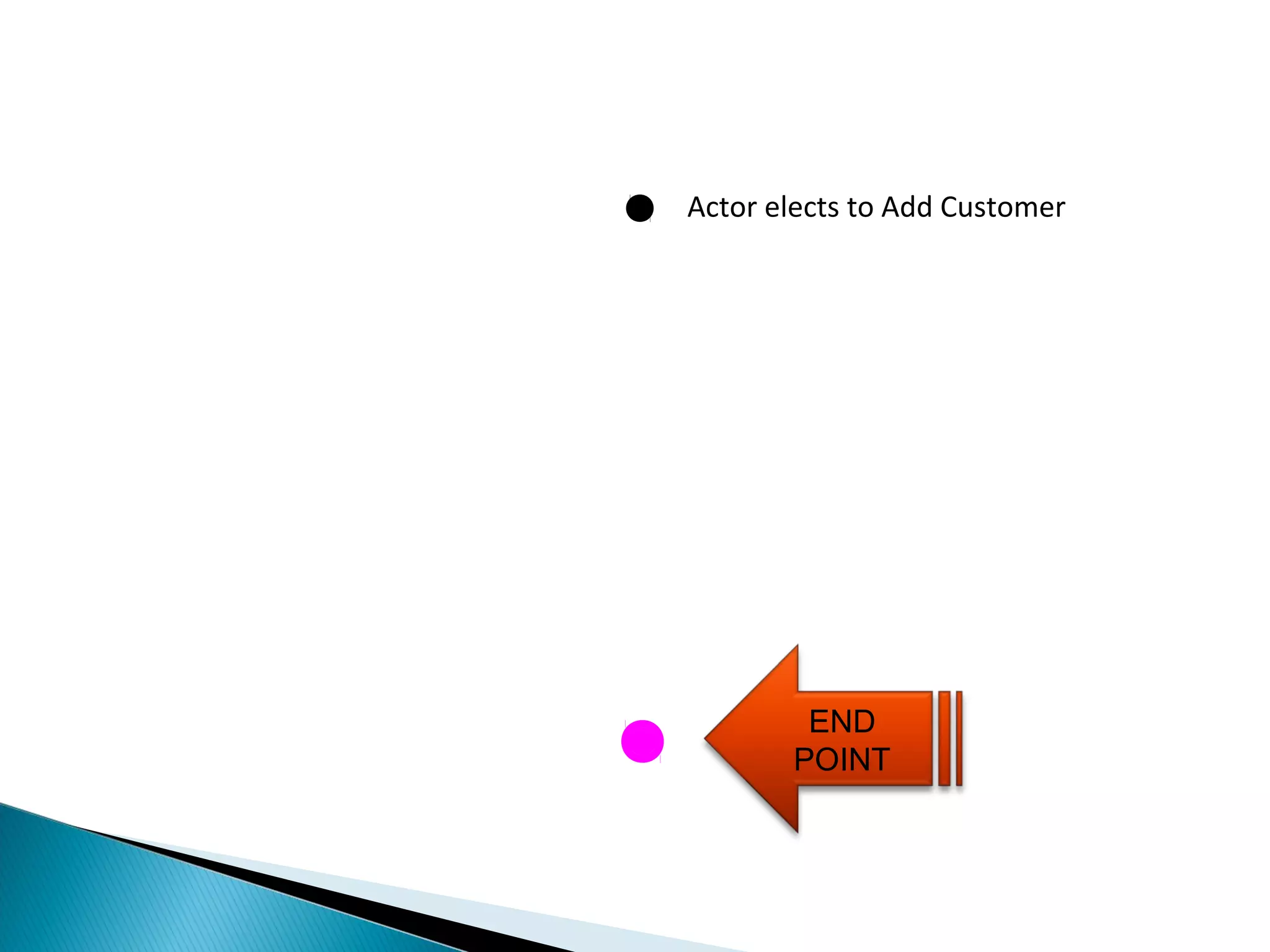
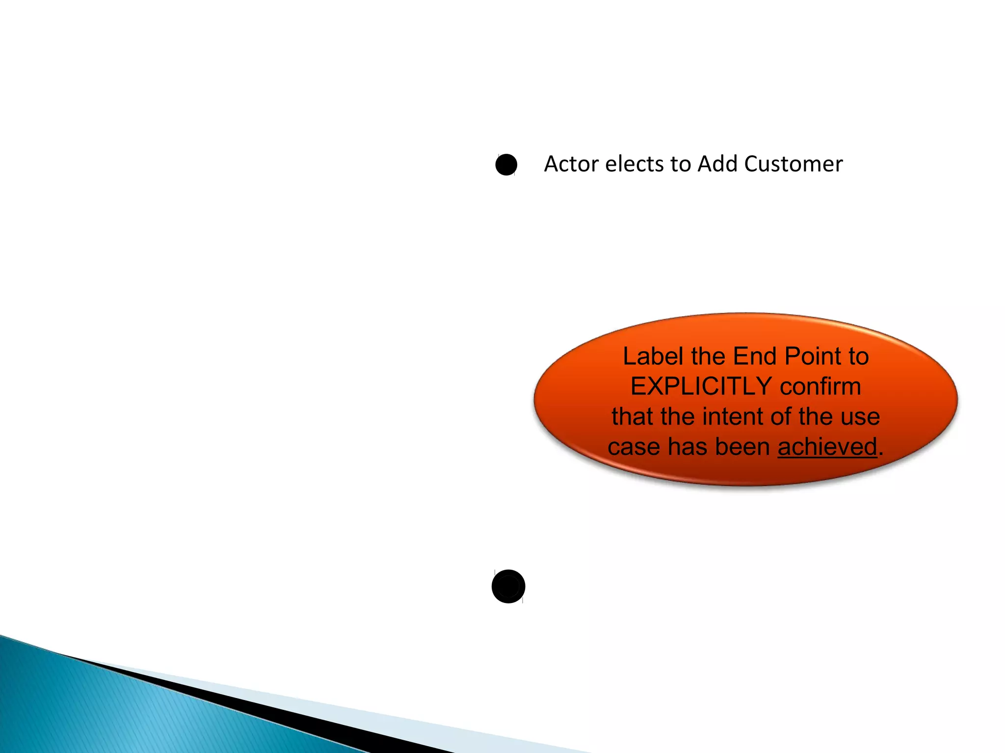
END POINT
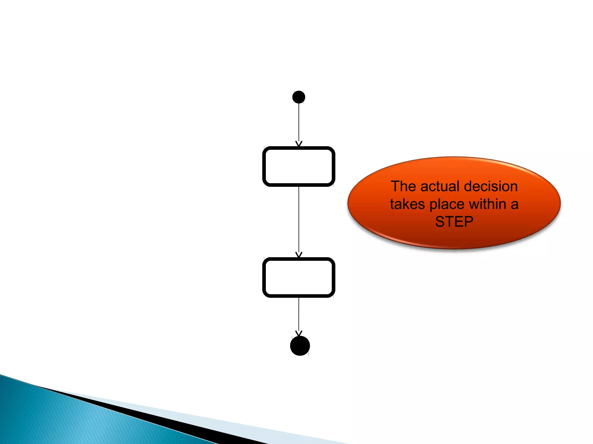
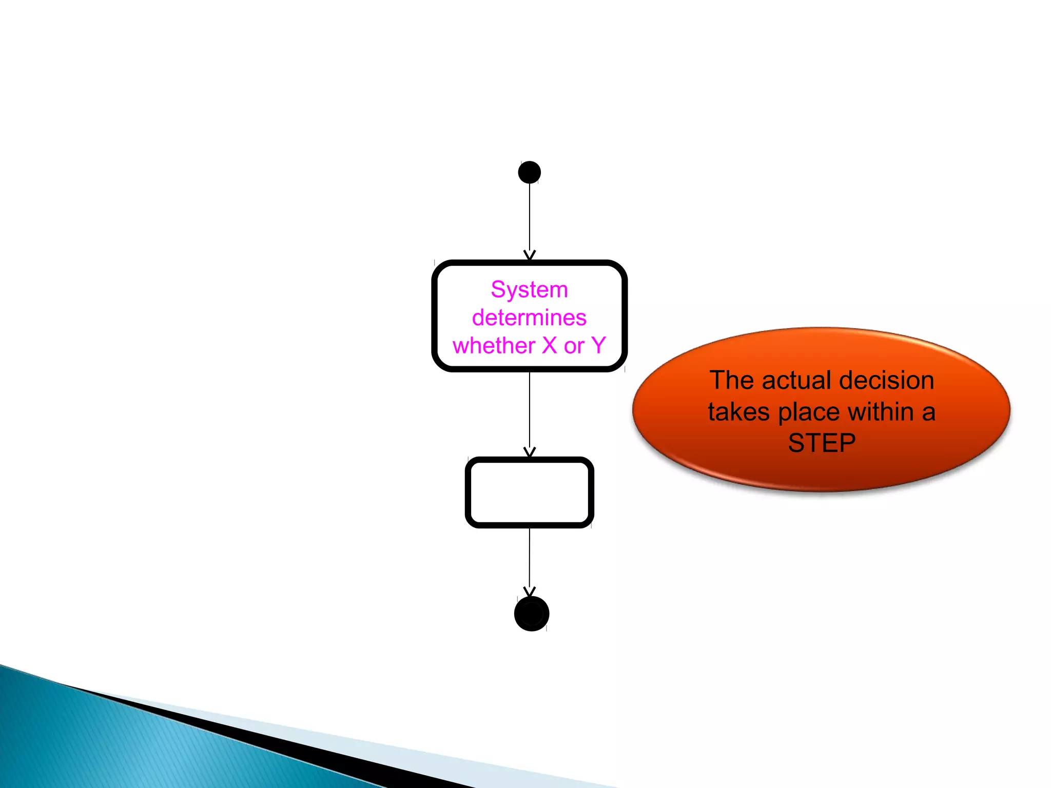
STEP
TRANSITION
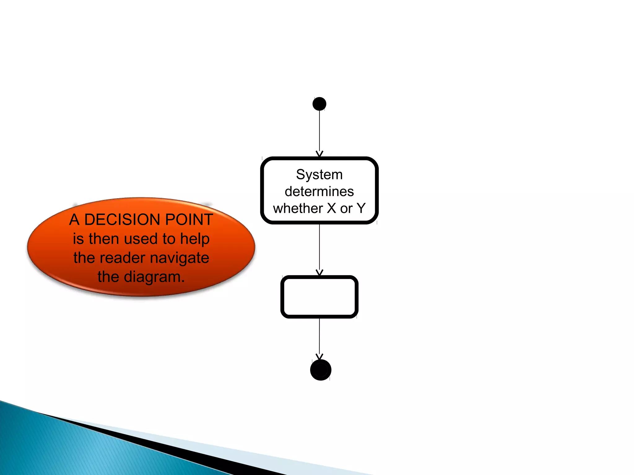
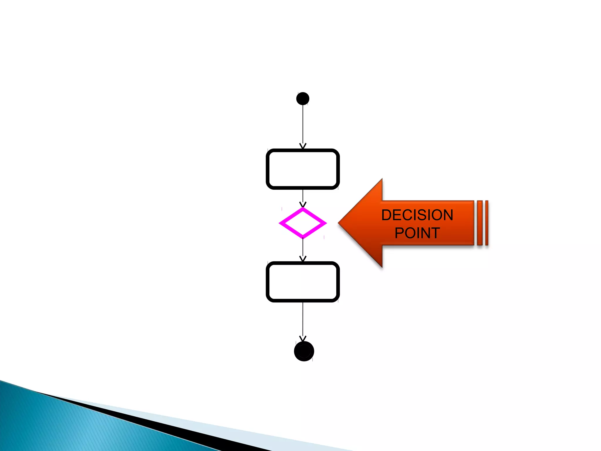
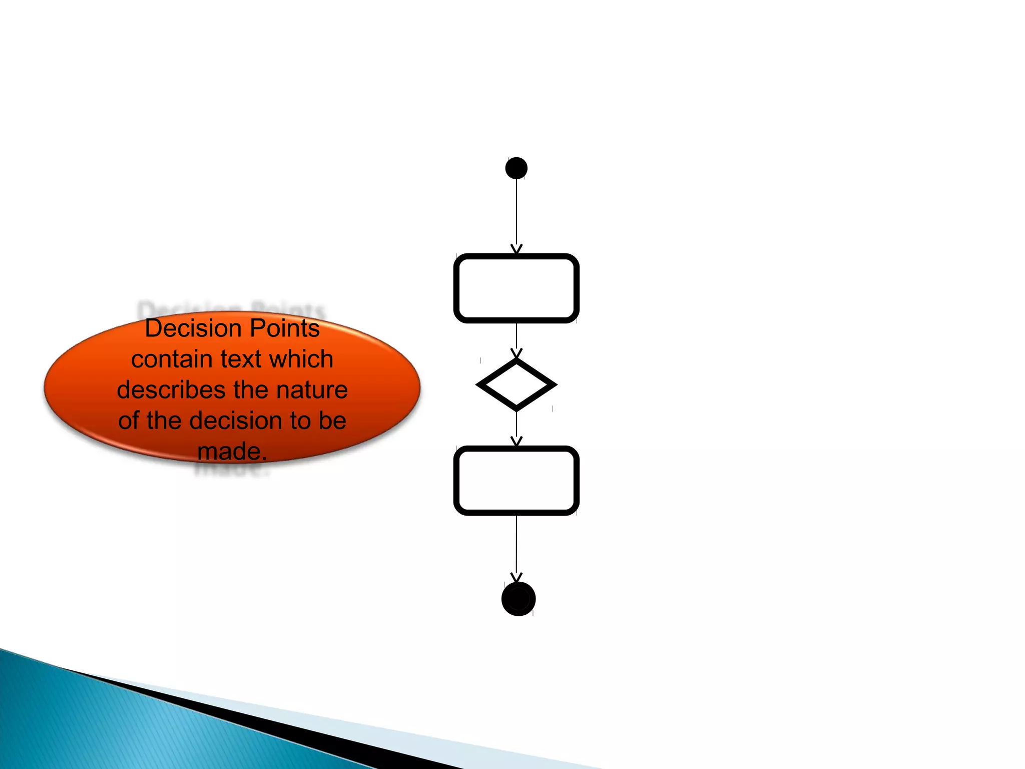
DECISION POINT
GUARD
PARALLEL STEPS
REPEATED STEPS](https://image.slidesharecdn.com/unit-3advancedstatemodelinginteractionmeodelling-140929182830-phpapp02/75/Unit-3-advanced-state-modeling-interaction-meodelling-109-2048.jpg)


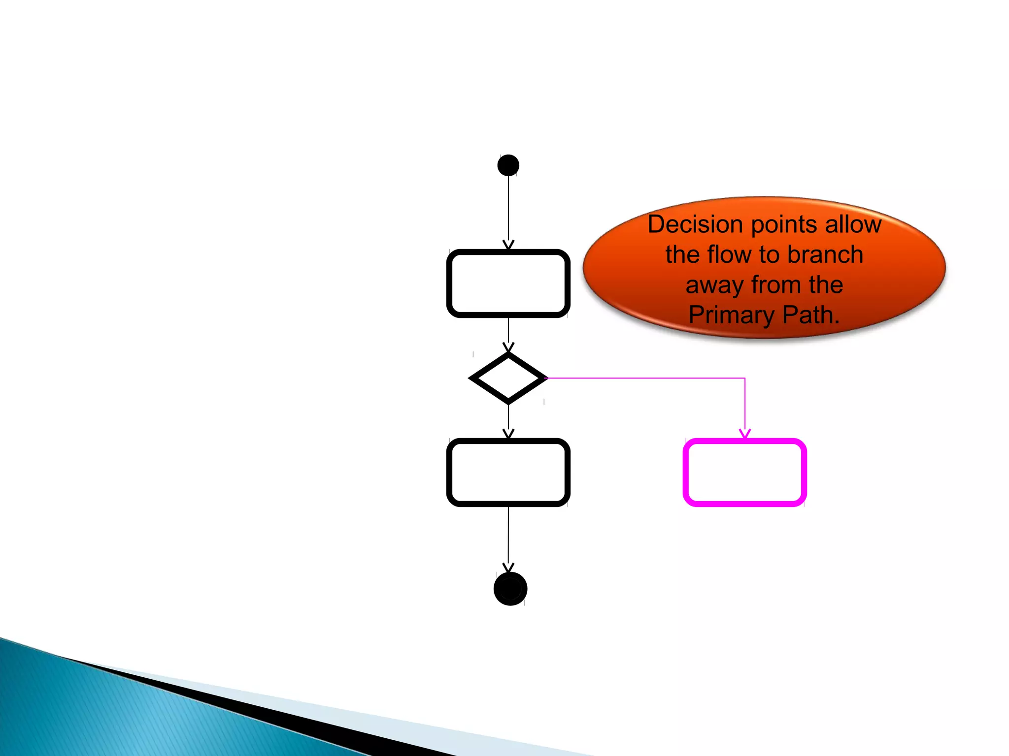
![[Condition 2]
[Condition 1]
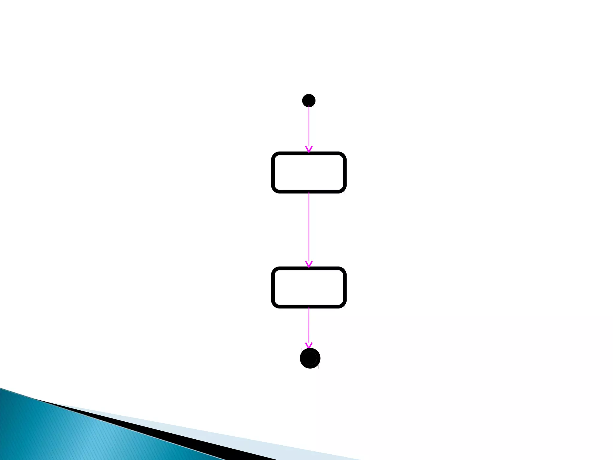
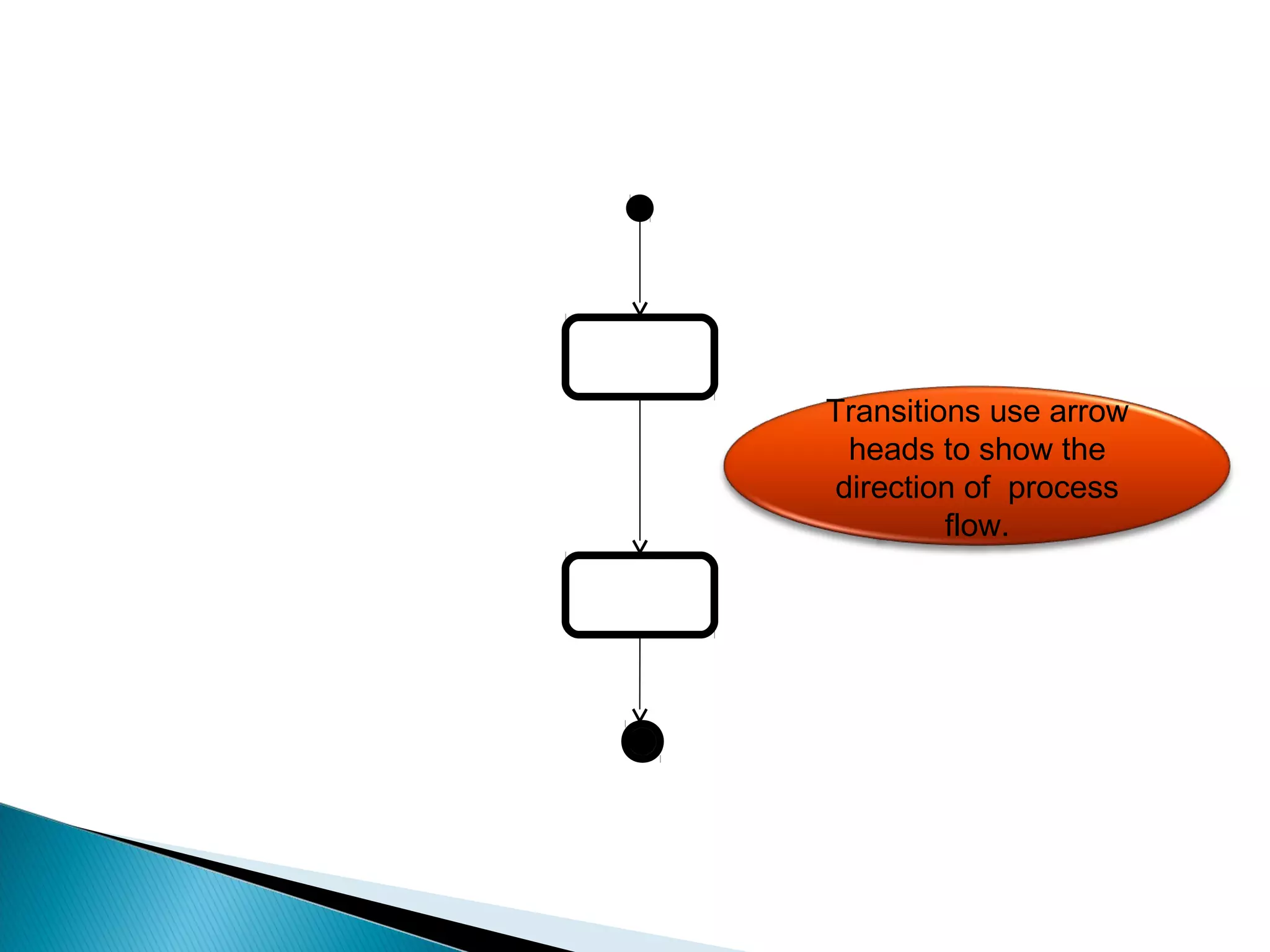
Transitions
coming out of
Decision Points
must have a
GUARD.](https://image.slidesharecdn.com/unit-3advancedstatemodelinginteractionmeodelling-140929182830-phpapp02/75/Unit-3-advanced-state-modeling-interaction-meodelling-135-2048.jpg)
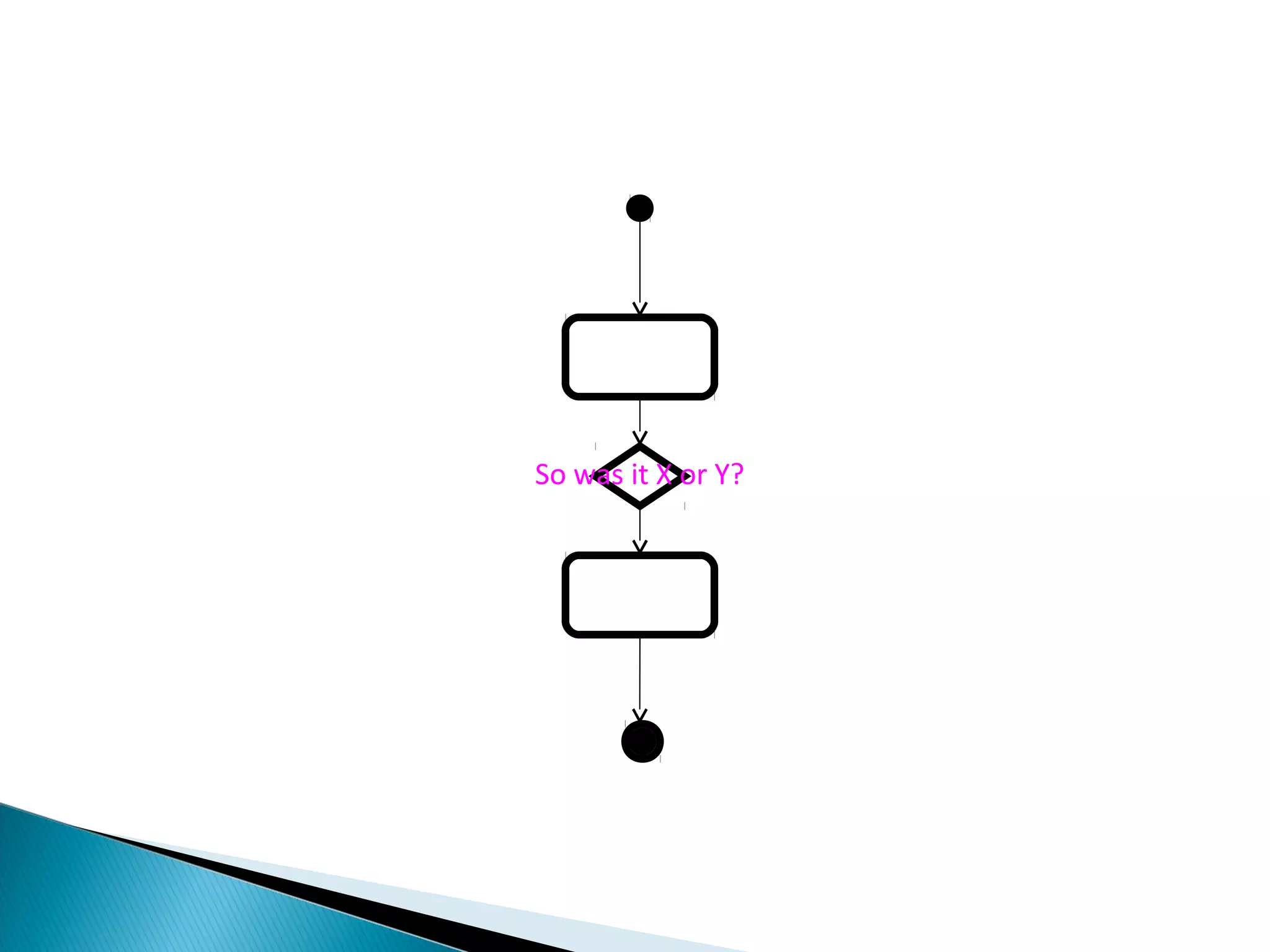
![[IT WAS “Y”]
[IT WAS “X”]
A Guard needs to
explicitly describe a
condition which must
be true in order to
proceed down that
path.](https://image.slidesharecdn.com/unit-3advancedstatemodelinginteractionmeodelling-140929182830-phpapp02/75/Unit-3-advanced-state-modeling-interaction-meodelling-136-2048.jpg)
![[Condition 2]
[Condition 1]
If the flow
rejoins the
Primary Path, it
is known as an
Alternate Path.](https://image.slidesharecdn.com/unit-3advancedstatemodelinginteractionmeodelling-140929182830-phpapp02/75/Unit-3-advanced-state-modeling-interaction-meodelling-137-2048.jpg)
![[Condition 1] [Condition 2]
You can show how
paths rejoin by
using a MERGE
POINT.](https://image.slidesharecdn.com/unit-3advancedstatemodelinginteractionmeodelling-140929182830-phpapp02/75/Unit-3-advanced-state-modeling-interaction-meodelling-138-2048.jpg)
![[Condition 1] [Condition 2]
You can show how
paths rejoin by
using a MERGE
POINT.](https://image.slidesharecdn.com/unit-3advancedstatemodelinginteractionmeodelling-140929182830-phpapp02/75/Unit-3-advanced-state-modeling-interaction-meodelling-139-2048.jpg)
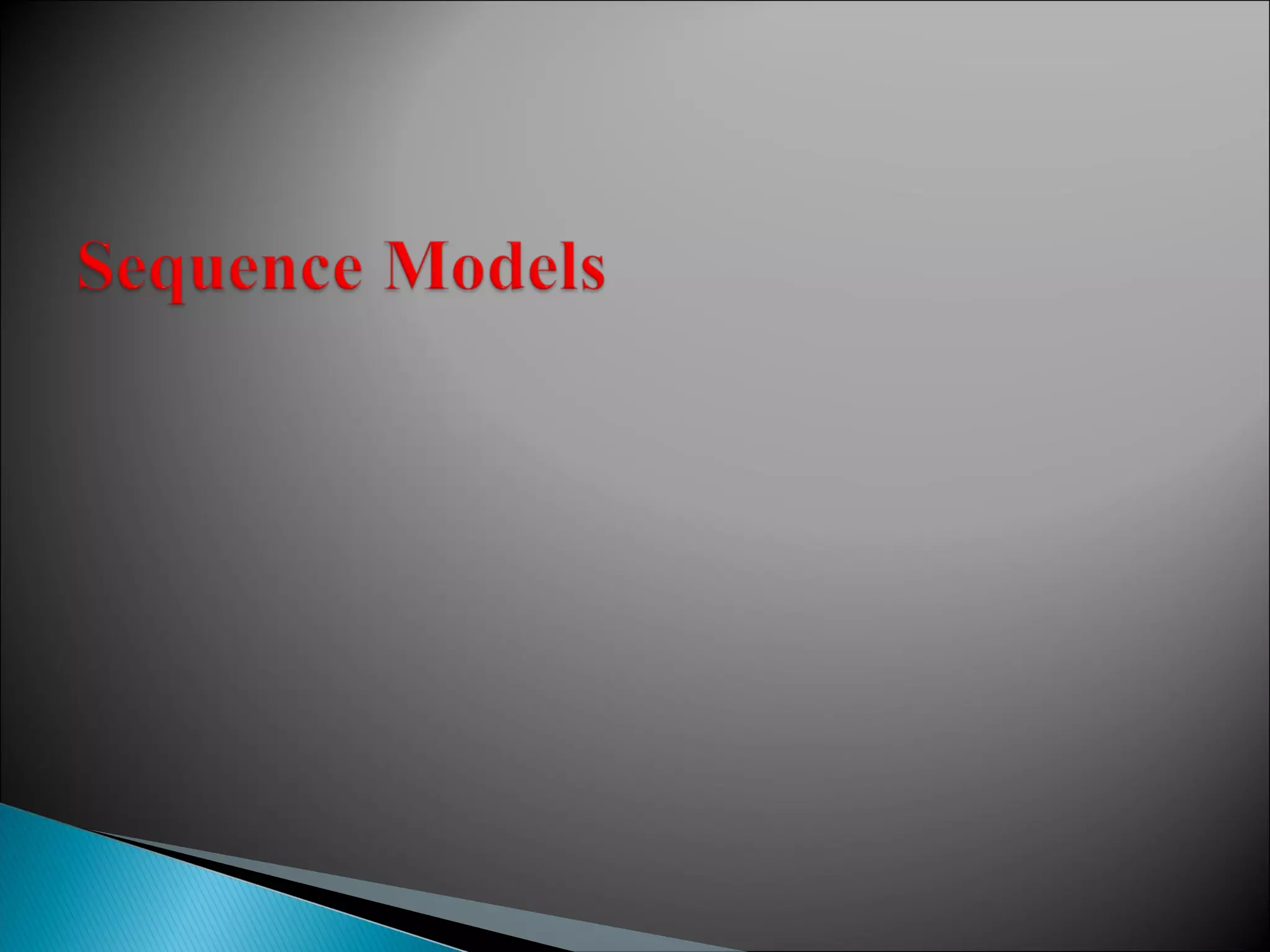
![[Condition 1] [Condition 2]
I prefer to model
merging paths like this.](https://image.slidesharecdn.com/unit-3advancedstatemodelinginteractionmeodelling-140929182830-phpapp02/75/Unit-3-advanced-state-modeling-interaction-meodelling-140-2048.jpg)

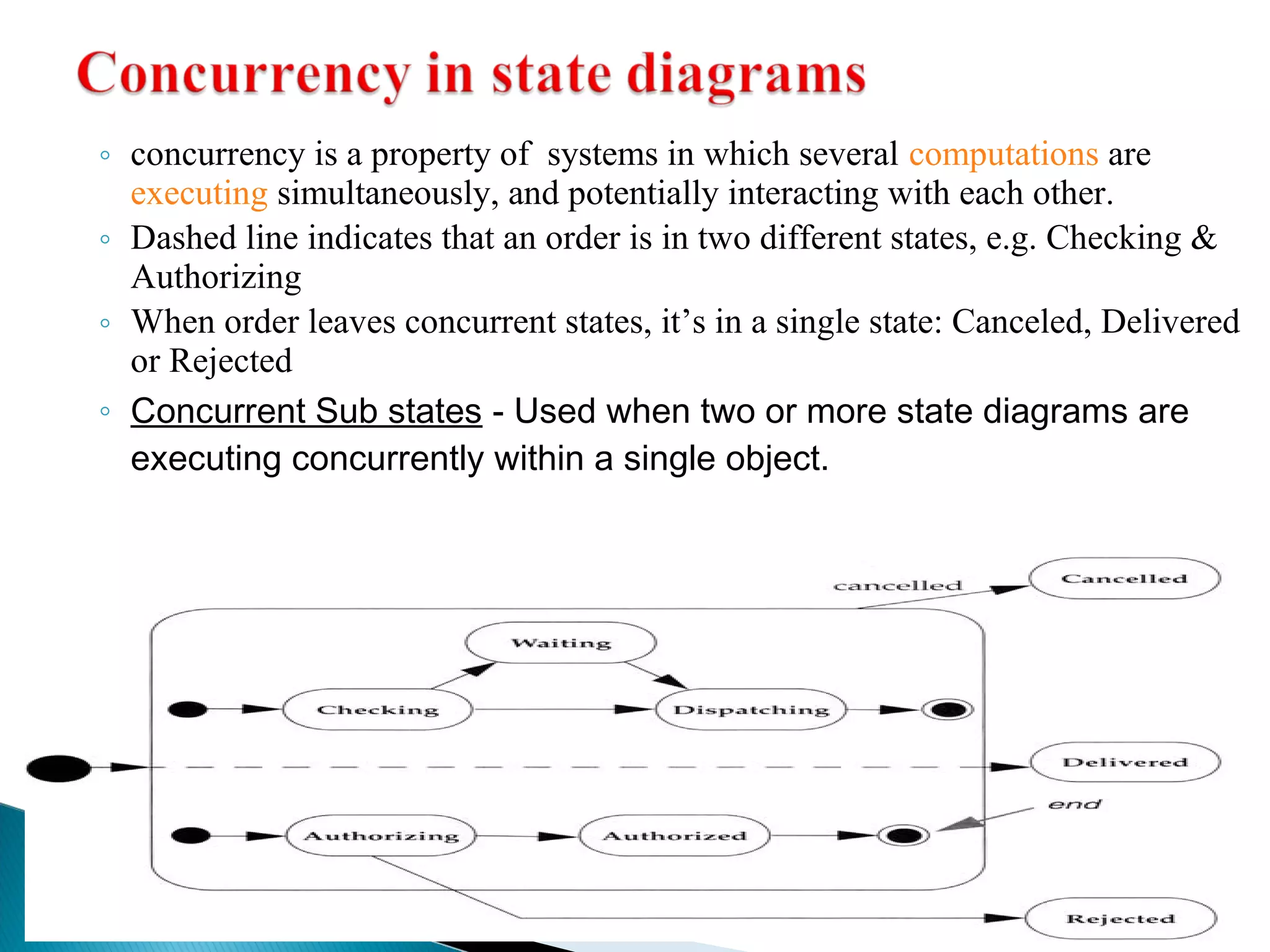
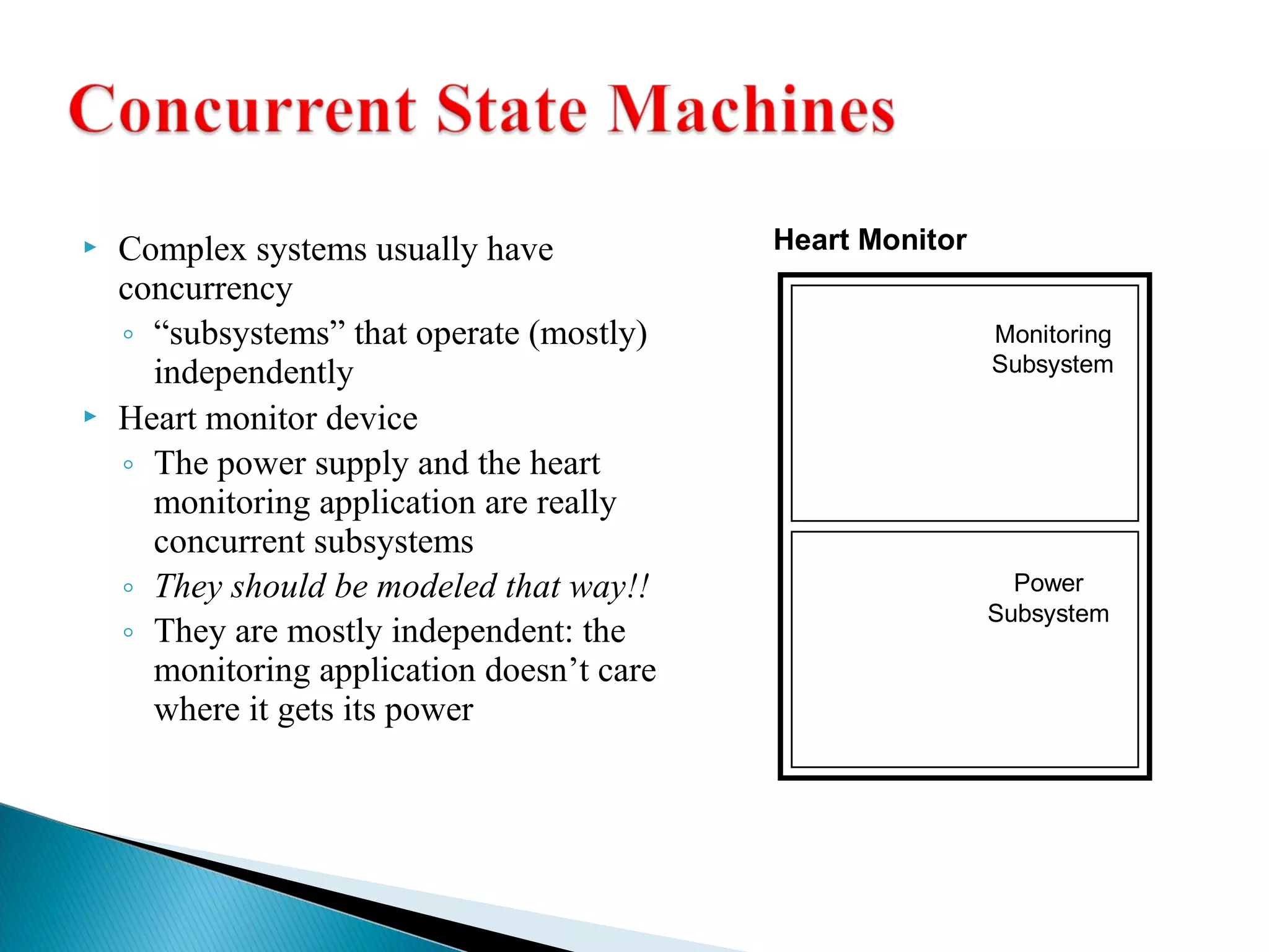
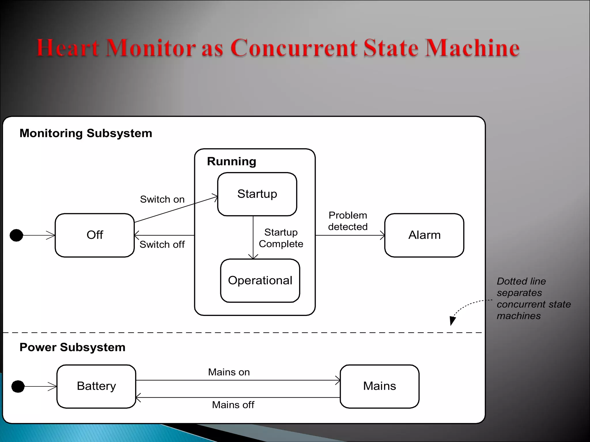
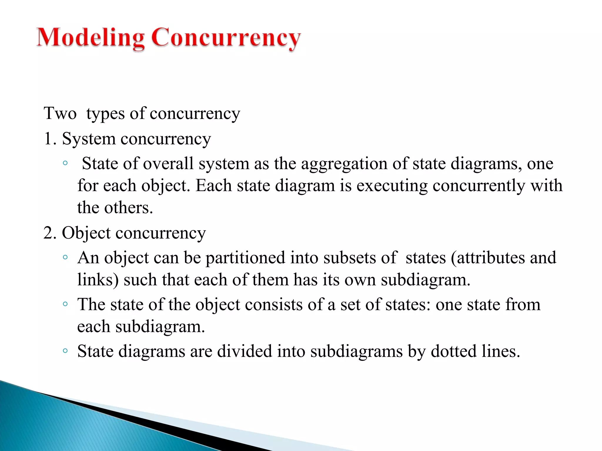
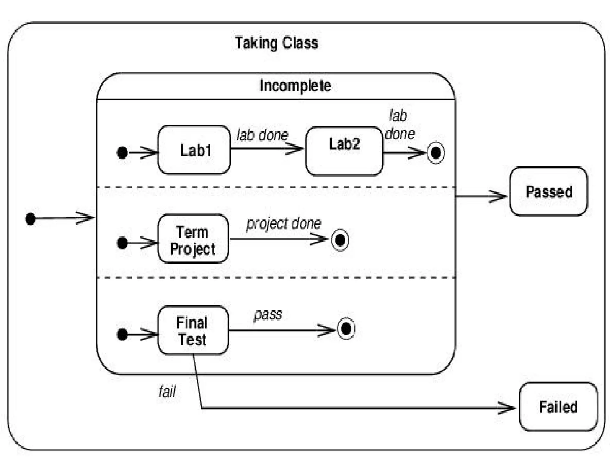
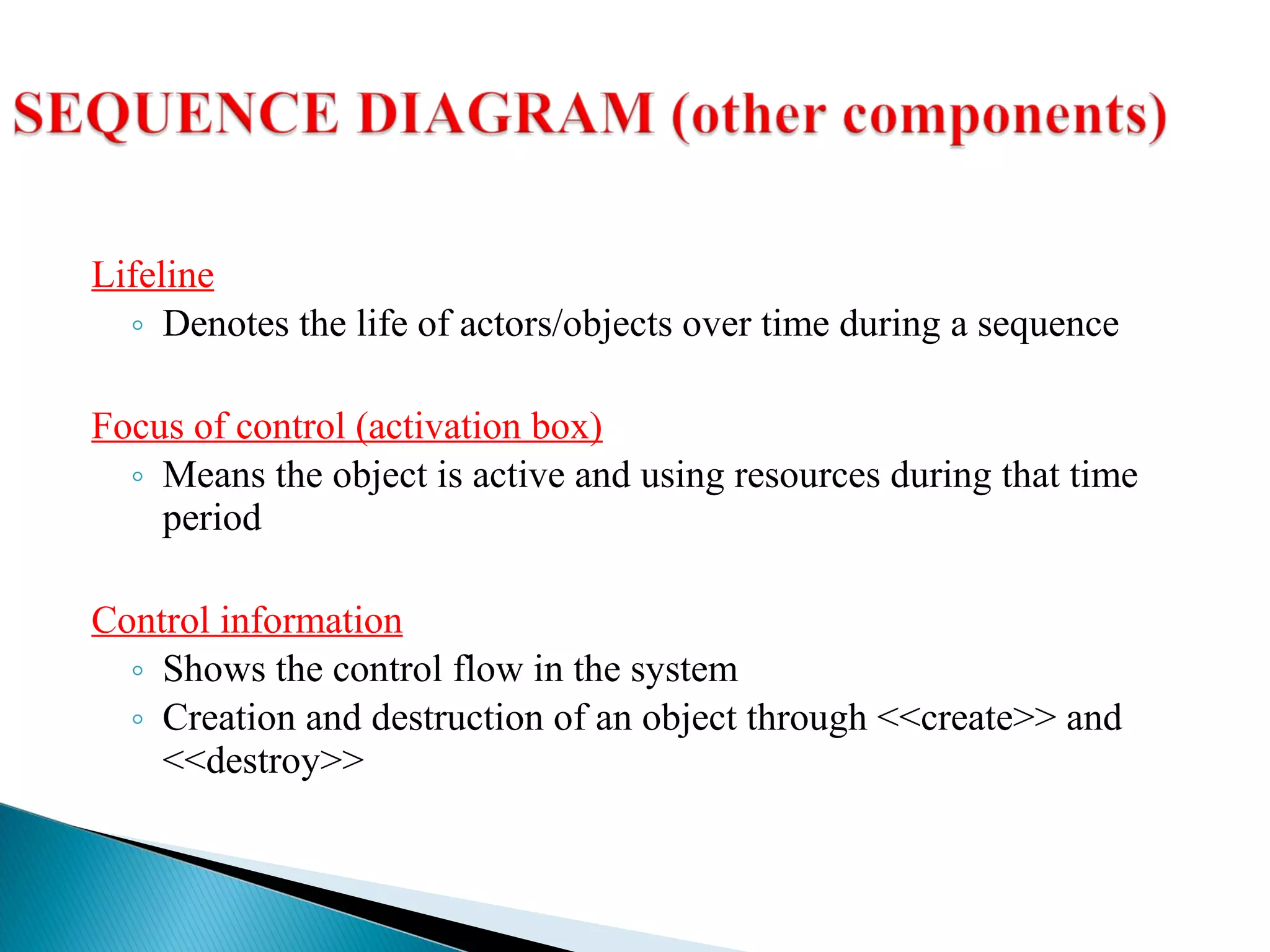
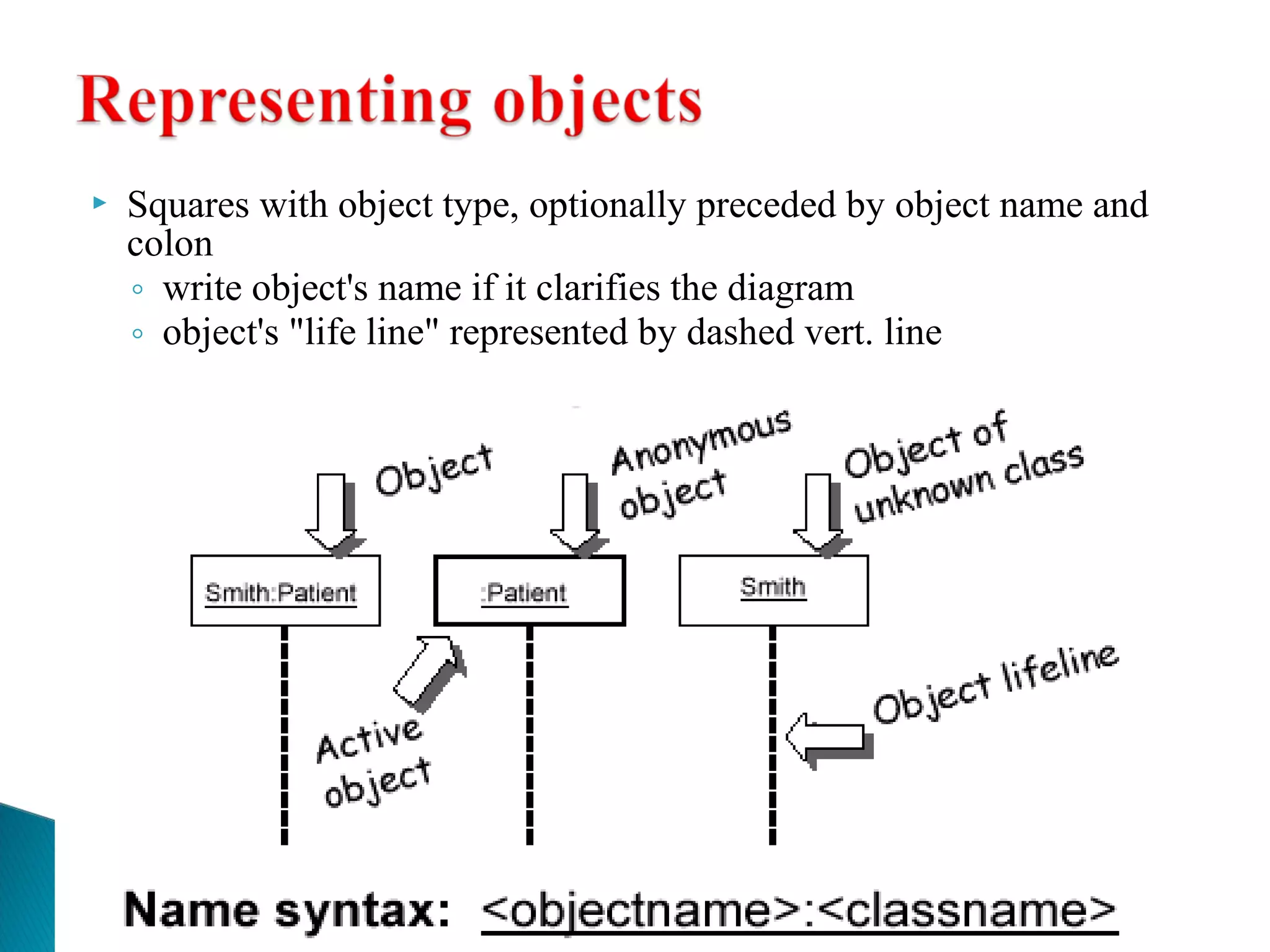
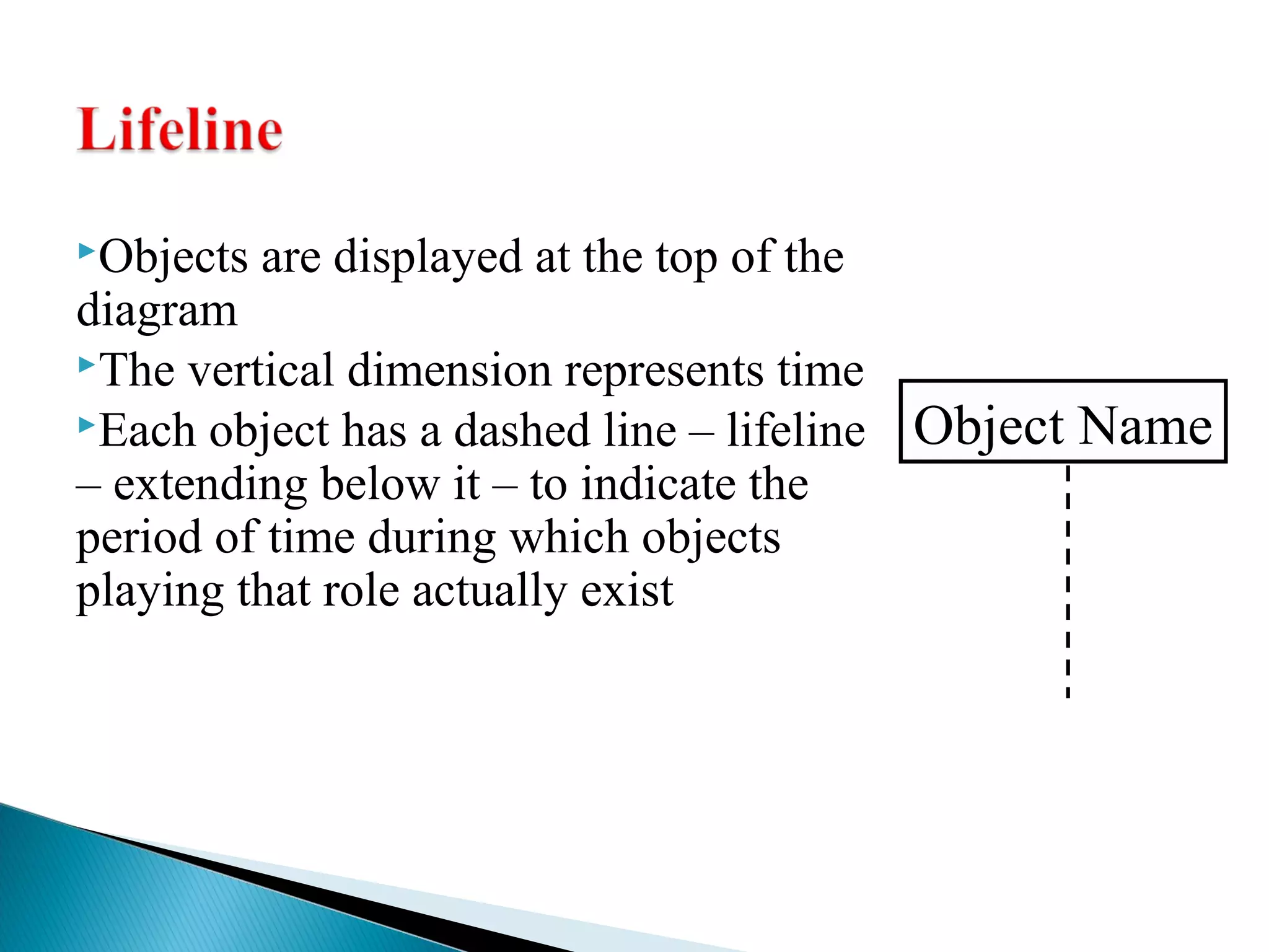
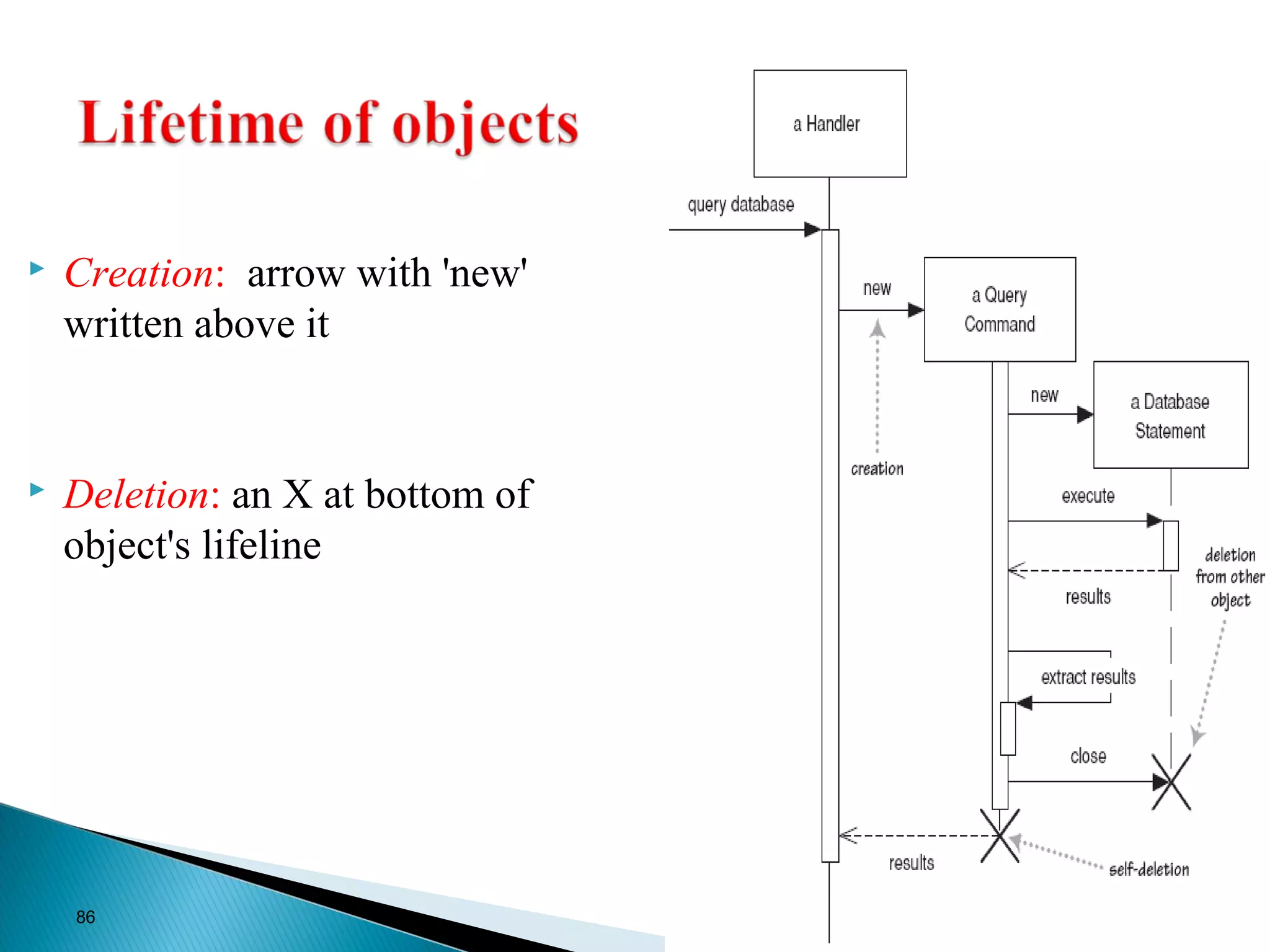
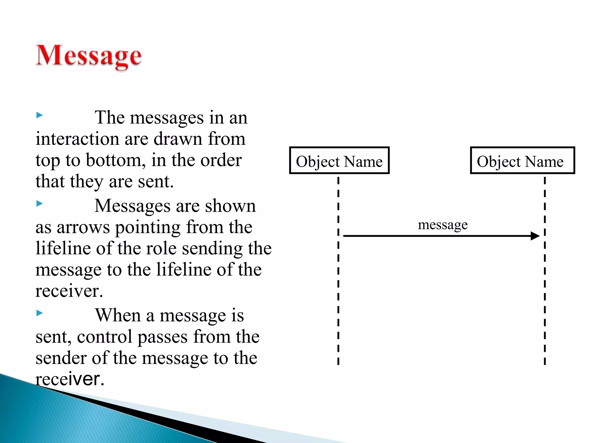
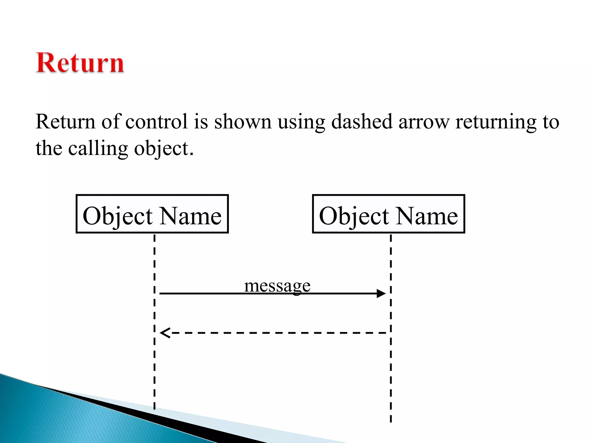
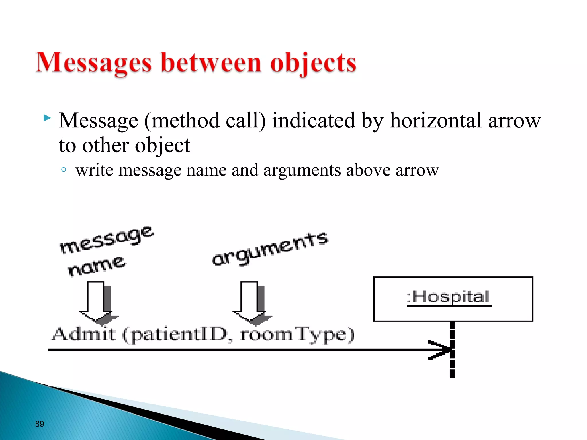
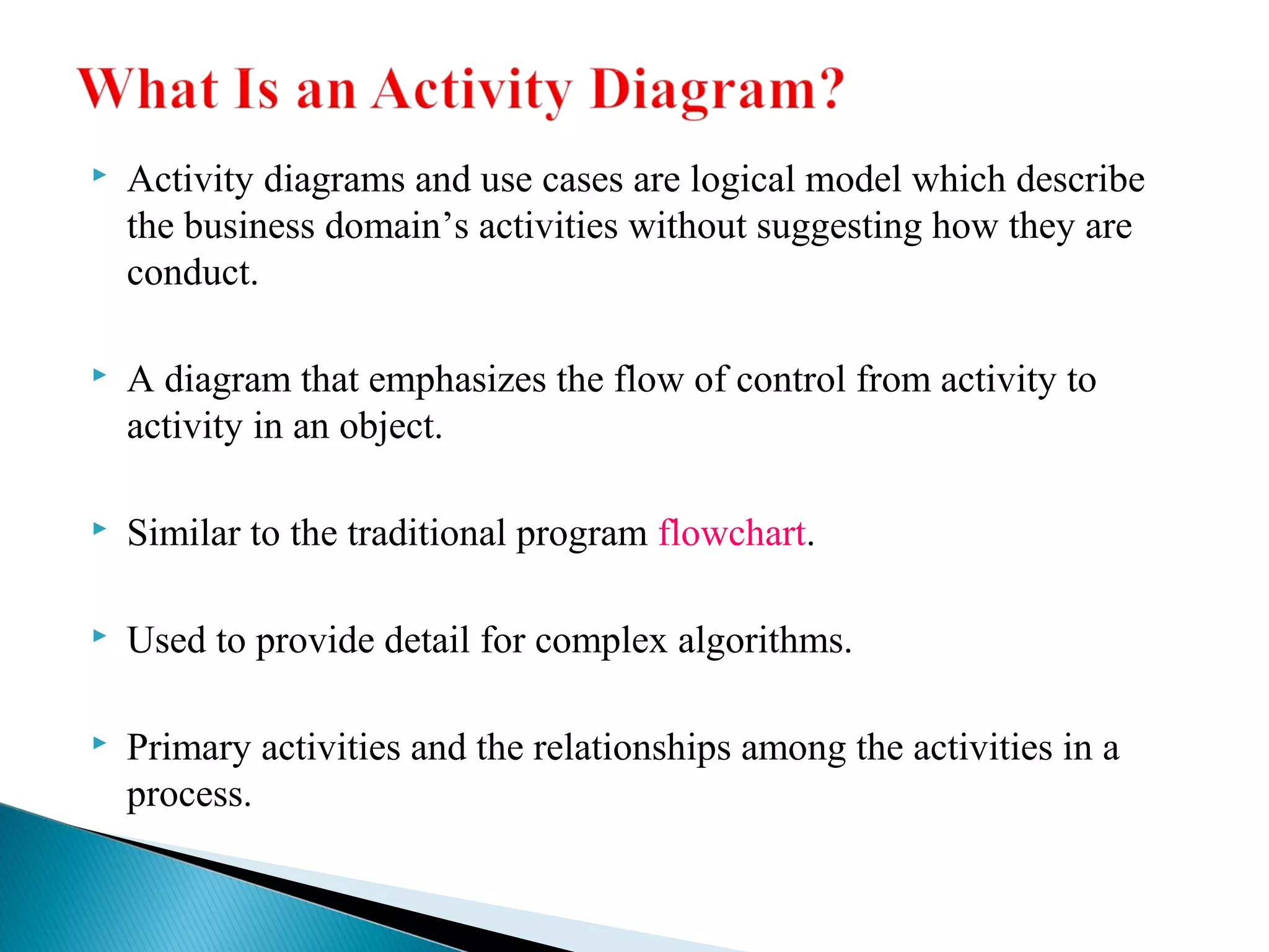
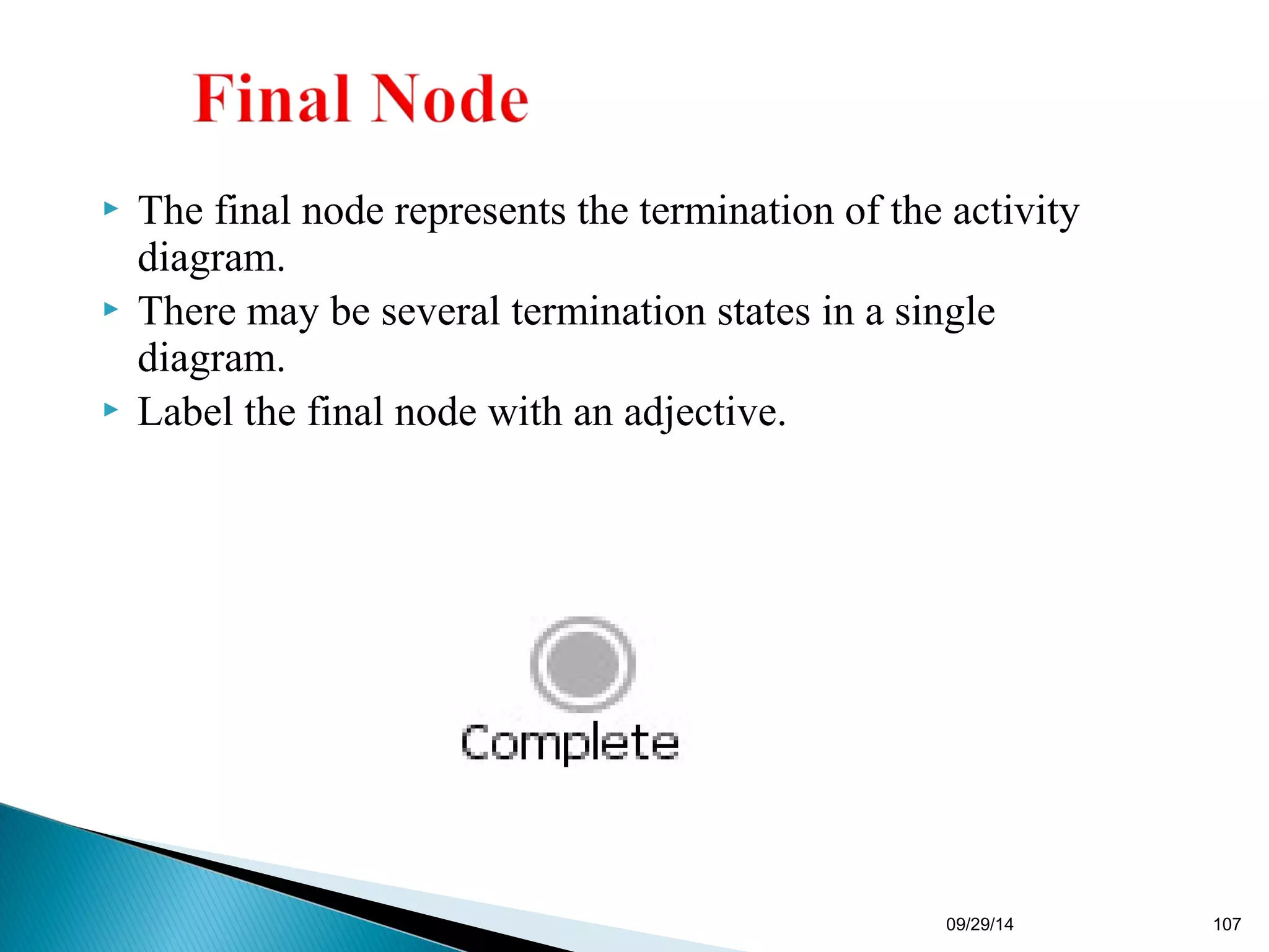
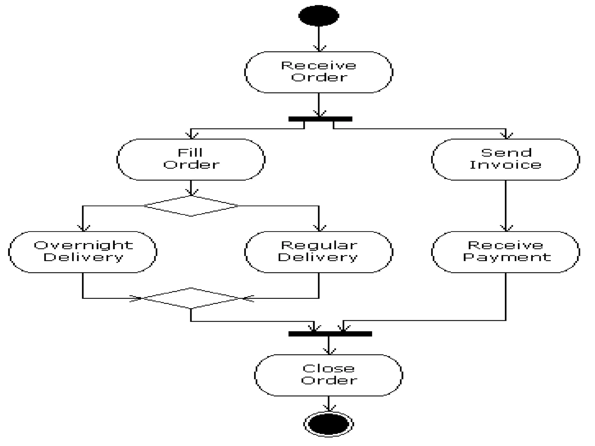
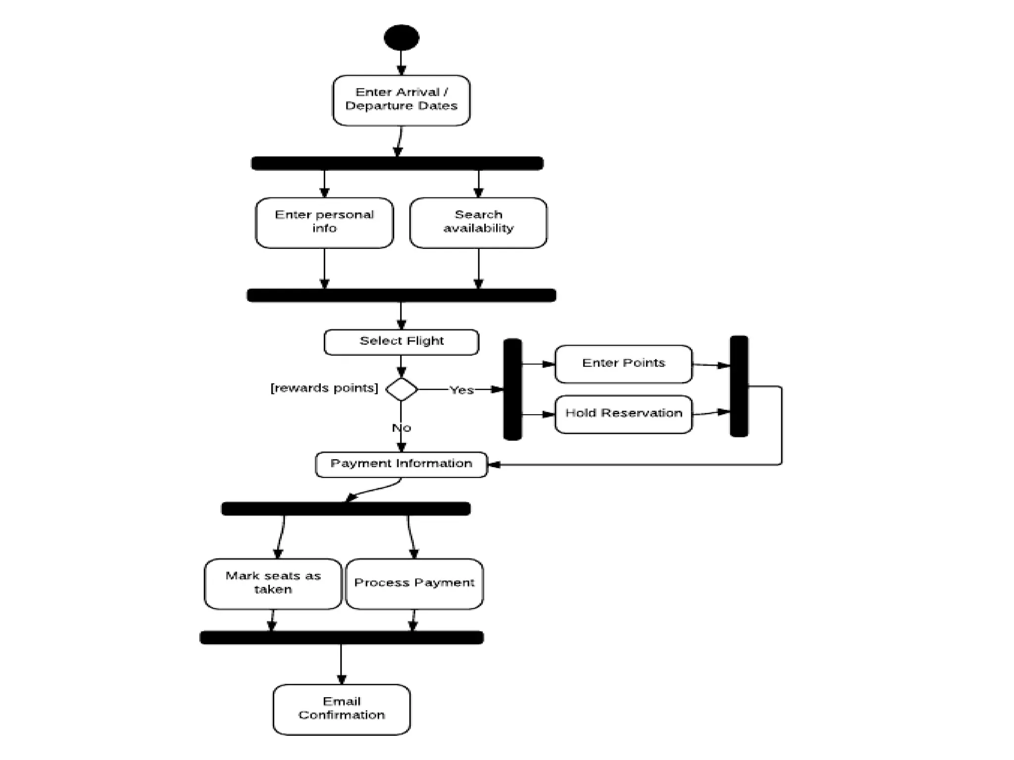
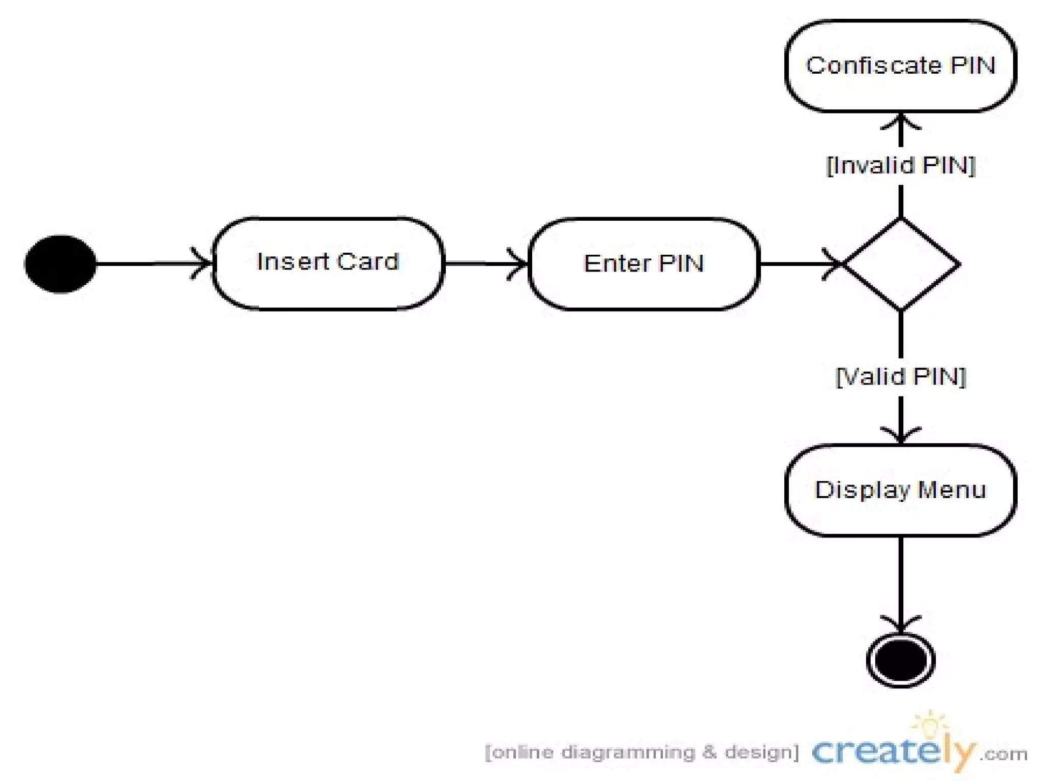
The document provides an overview of advanced state modeling and interaction modeling techniques in UML. It discusses nested state diagrams and concurrent state diagrams for controlling complexity in state diagrams. It also covers activity models, use case models, and sequence models for interaction modeling. The relationships between class models, state models, and interaction models are also briefly described.