Presentation Use Case Diagram and Use Case Specification.pptx
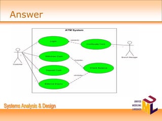
The use case diagram models the interactions between a Customer and an ATM machine. The Customer can perform the use cases of Logging In, Making a Withdrawal, Checking Balance, and Depositing Funds. The ATM machine facilitates these use cases.
Lecture Layout
Use CaseDiagram
Use Case
Actor
Relationship (include & extend)
Use Case Specification
4.
Objectives
Transform and representthe user
requirements into use case diagram using
UML notation
Develop use case specification
Identify basic flow, alternatives flow and
exceptional flows
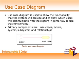
• Use casediagram is used to show the functionality
that the system will provide and to show which users
will communicate with the system in some way to use
that functionality.
• Primary components are : use cases, actors,
system/subsystem and relationships
actor use case
Basic use case diagram
Use Case Diagram
7.
To document thefunctionalities of the system from the
users’ perspective, resulting in an agreement between
the clients and the developers;
To document the scope of the system
To document the interaction between the users and the
system using supporting use case descriptions
To provide basis for performing system tests
To provide the ability to trace functional requirements
into implementation later on
Purpose of Use Case Diagram
8.
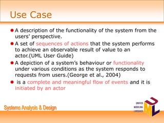
A description ofthe functionality of the system from the
users’ perspective.
A set of sequences of actions that the system performs
to achieve an observable result of value to an
actor.(UML User Guide)
A depiction of a system’s behaviour or functionality
under various conditions as the system responds to
requests from users.(George et al., 2004)
is a complete and meaningful flow of events and it is
initiated by an actor
Use Case
9.
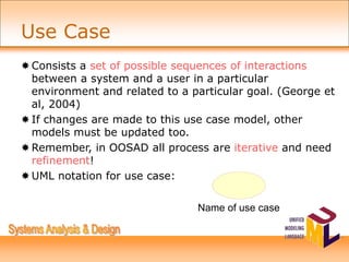
Consists a setof possible sequences of interactions
between a system and a user in a particular
environment and related to a particular goal. (George et
al, 2004)
If changes are made to this use case model, other
models must be updated too.
Remember, in OOSAD all process are iterative and need
refinement!
UML notation for use case:
Name of use case
Use Case
10.
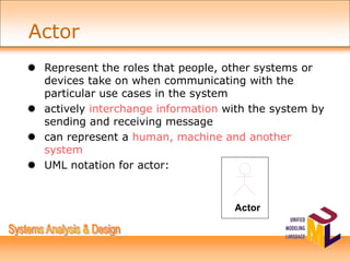
Represent theroles that people, other systems or
devices take on when communicating with the
particular use cases in the system
actively interchange information with the system by
sending and receiving message
can represent a human, machine and another
system
UML notation for actor:
Actor
Actor
11.
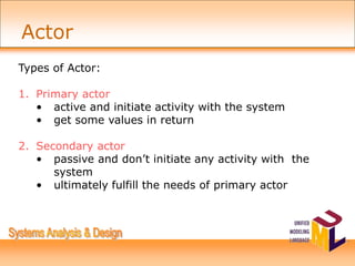
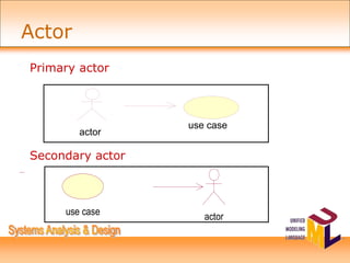
Types of Actor:
1.Primary actor
• active and initiate activity with the system
• get some values in return
2. Secondary actor
• passive and don’t initiate any activity with the
system
• ultimately fulfill the needs of primary actor
Actor
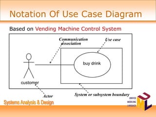
customer
buy drink
System orsubsystem boundary
Actor
Use case
Communication
association
Based on Vending Machine Control System
Notation Of Use Case Diagram
14.
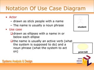
• Actor
– drawnas stick people with a name
– The name is usually a noun phrase
Use case
drawn as ellipses with a name in or
below each ellipse
the name is usually an active verb (what
the system is supposed to do) and a
noun phrase (what the system to act
on) print bill
student
Notation Of Use Case Diagram
15.
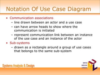
• Communication associations
–line drawn between an actor and a use case
– can have arrow heads to show where the
communication is initiated
– represent communication link between an instance
of the use case and an instance of the actor
• Sub-systems
– drawn as a rectangle around a group of use cases
that belongs to the same sub-system
Notation Of Use Case Diagram
16.
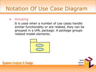
• Grouping
It isused when a number of use cases handle
similar functionality or are related, they can be
grouped in a UML package. A package groups
related model elements.
Notation Of Use Case Diagram
17.
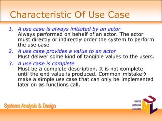
1. A usecase is always initiated by an actor
Always performed on behalf of an actor. The actor
must directly or indirectly order the system to perform
the use case.
2. A use case provides a value to an actor
Must deliver some kind of tangible values to the users.
3. A use case is complete
Must be a complete description. It is not complete
until the end value is produced. Common mistake
make a simple use case that can only be implemented
later on as functions call.
Characteristic Of Use Case
18.
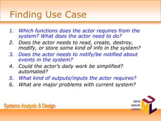
1. Which functionsdoes the actor requires from the
system? What does the actor need to do?
2. Does the actor needs to read, create, destroy,
modify, or store some kind of info in the system?
3. Does the actor needs to notify/be notified about
events in the system?
4. Could the actor’s daily work be simplified?
automated?
5. What kind of outputs/inputs the actor requires?
6. What are major problems with current system?
Finding Use Case
19.
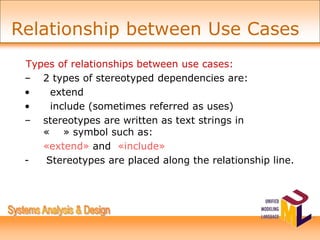
Types of relationshipsbetween use cases:
– 2 types of stereotyped dependencies are:
• extend
• include (sometimes referred as uses)
– stereotypes are written as text strings in
« » symbol such as:
«extend» and «include»
- Stereotypes are placed along the relationship line.
Relationship between Use Cases
20.
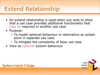
• An extendrelationship is used when you wish to show
that a use case provides additional functionality that
may be required in another use case.
• Purpose:
– To model optional behaviour or alternative at certain
point in separate use case.
– To mitigate the complexity of base use case
• View as optional system behaviour
Extend Relationship
21.
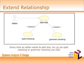
editor
spell checking grammarchecking
edit text
<<extend>> <<extend>>
Every time an editor wants to edit text, he can do spell
checking or grammar checking use case
Extend Relationship
22.
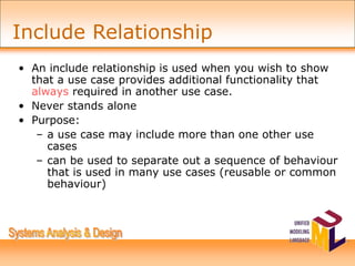
• An includerelationship is used when you wish to show
that a use case provides additional functionality that
always required in another use case.
• Never stands alone
• Purpose:
– a use case may include more than one other use
cases
– can be used to separate out a sequence of behaviour
that is used in many use cases (reusable or common
behaviour)
Include Relationship
23.
customer
deposit funds
withdraw money
verifycustomer
<<include>>
<<include>>
Every time a customer wants to deposit funds, he must verify
himself to the system.
Include Relationship
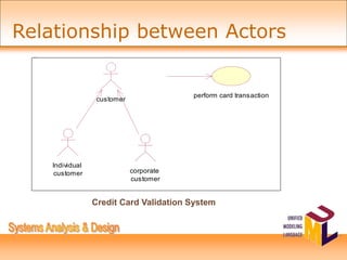
24.
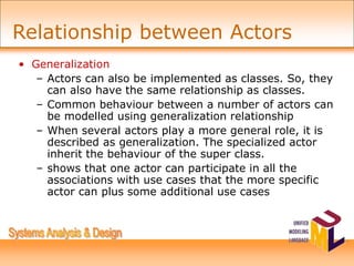
• Generalization
– Actorscan also be implemented as classes. So, they
can also have the same relationship as classes.
– Common behaviour between a number of actors can
be modelled using generalization relationship
– When several actors play a more general role, it is
described as generalization. The specialized actor
inherit the behaviour of the super class.
– shows that one actor can participate in all the
associations with use cases that the more specific
actor can plus some additional use cases
Relationship between Actors
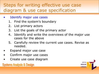
• Identify majoruse cases
1. Find the system’s boundary
2. List primary actors
3. List the goals of the primary actor
4. Identify and write the overviews of the major use
cases for the above
5. Carefully review the current use cases. Revise as
needed.
• Expand major use case
• Confirm major use cases
• Create use case diagram
Steps for writing effective use case
diagram & use case specification
27.
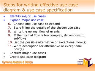
• Identify majoruse cases
• Expand major use case
6. Choose one use case to expand
7. Start filling the details of the chosen use case
8. Write the normal flow of events
9. If the normal flow is too complex, decompose to
subflows
10. List the possible alternative or exceptional flow(s)
11. Write description for alternative or exceptional
flow(s)
• Confirm major use cases
• Create use case diagram
Steps for writing effective use case
diagram & use case specification
28.
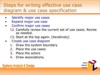
• Identify majoruse cases
• Expand major use case
• Confirm major use cases
12. Carefully review the current set of use cases. Revise
as needed.
13. Start at the top again. (iteratively)
• Create use case diagram
1. Draw the system boundary
2. Place the use cases
3. Place the actors
4. Draw associations.
Steps for writing effective use case
diagram & use case specification
29.
• Show onlythose use cases that are important to
understand the behavior of the system in its context.
• Show only those actors that relate to these use cases.
• Each use case diagram should focus on
communicating one aspect of a system.
• Try to keep them simple.
Guidelines for Use Case Diagram
30.
• Names asingle, identifiable, and reasonably atomic
behavior of the system.
• Describes the flow of events clearly enough for an
outsider to easily understand it.
• Factor common behavior by pulling such behavior
from use cases that it includes.
• Factor variant behavior by pushing such behavior into
other use cases that extend it.
Guidelines for Use Case Diagram
• Use CaseSpecification is known as Use Case
Description.
• The Use Case Specification includes:
Brief description:
• Summary of use case
• Describe the use case not more than 5
lines.
Use Case Specification
33.
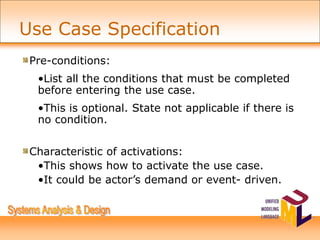
Pre-conditions:
•List all theconditions that must be completed
before entering the use case.
•This is optional. State not applicable if there is
no condition.
Characteristic of activations:
•This shows how to activate the use case.
•It could be actor’s demand or event- driven.
Use Case Specification
34.
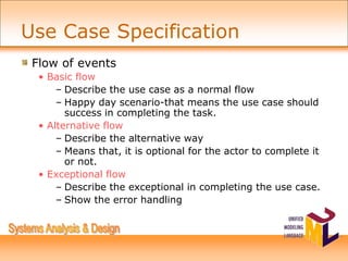
Flow of events
•Basic flow
– Describe the use case as a normal flow
– Happy day scenario-that means the use case should
success in completing the task.
• Alternative flow
– Describe the alternative way
– Means that, it is optional for the actor to complete it
or not.
• Exceptional flow
– Describe the exceptional in completing the use case.
– Show the error handling
Use Case Specification
35.
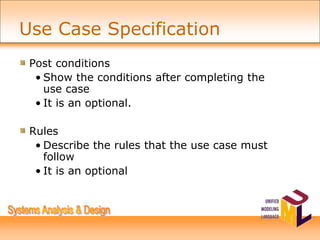
Post conditions
• Showthe conditions after completing the
use case
• It is an optional.
Rules
• Describe the rules that the use case must
follow
• It is an optional
Use Case Specification
36.
–Constraints
•Describe the limitationthat the use case have
•It is an optional
For complete example, refer to Use Case
Specification f
Use Case Specification
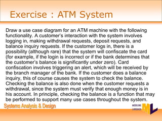
Draw a usecase diagram for an ATM machine with the following
functionality. A customer’s interaction with the system involves
logging in, making withdrawal requests, deposit requests, and
balance inquiry requests. If the customer logs in, there is a
possibility (although rare) that the system will confiscate the card
(for example, if the login is incorrect or if the bank determines that
the customer’s balance is significantly under zero). Card
confiscation involves triggering an alert, which will be received by
the branch manager of the bank. If the customer does a balance
inquiry, this of course causes the system to check the balance.
Checking the balance is also done when the customer requests a
withdrawal, since the system must verify that enough money is in
his account. In principle, checking the balance is a function that may
be performed to support many use cases throughout the system.
Exercise : ATM System