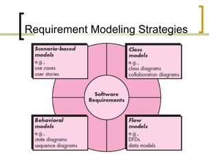
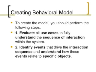
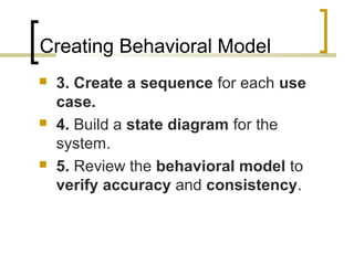
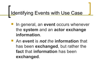
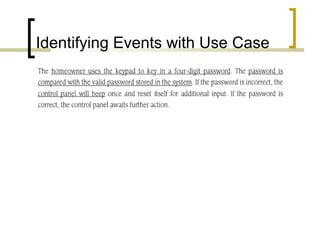
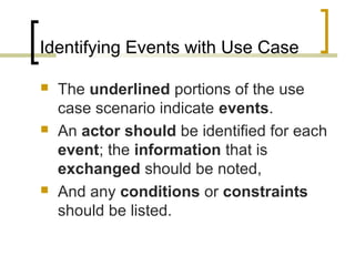
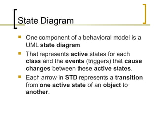
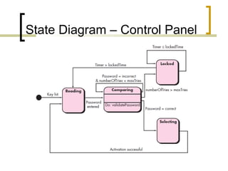
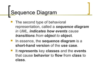
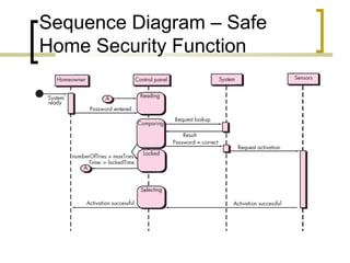
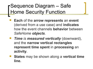
Introduction to Software Engineering 
Muhammad Nasir 
Requirements Modeling – Data 
Flow & Behavior (2) 
m.nasir@iiu.edu.pk
Agenda 
 Creating Behavioral Model 
 Identifying event in Use cases 
 State Diagram 
 Sequence Diagram
Requirement Modeling Strategies
Elements of UML Behavioral Models 
 State Diagram 
 Sequence Diagram
Creating Behavioral Model 
 The modeling notation that we have 
discussed to this point represents static 
elements of the requirements model. 
 It is now time to make a transition to the 
dynamic behavior of the system or product. 
 To accomplish this, you can represent the 
behavior of the system as a function of 
specific events and time.
Creating Behavioral Model 
 The behavioral model indicates how 
software will respond to external 
events or stimuli.
Creating Behavioral Model 
 To create the model, you should perform the 
following steps: 
 1. Evaluate all use cases to fully 
understand the sequence of interaction 
within the system. 
 2. Identify events that drive the interaction 
sequence and understand how these 
events relate to specific objects.
Creating Behavioral Model 
 3. Create a sequence for each use 
case. 
 4. Build a state diagram for the 
system. 
 5. Review the behavioral model to 
verify accuracy and consistency.
Identifying Events with Use Case 
 In general, an event occurs whenever 
the system and an actor exchange 
information. 
 An event is not the information that 
has been exchanged, but rather the 
fact that information has been 
exchanged.
Identifying Events with Use Case
Identifying Events with Use Case 
 The underlined portions of the use 
case scenario indicate events. 
 An actor should be identified for each 
event; the information that is 
exchanged should be noted, 
 And any conditions or constraints 
should be listed.
State Diagram 
 One component of a behavioral model is a 
UML state diagram 
 That represents active states for each 
class and the events (triggers) that cause 
changes between these active states. 
 Each arrow in STD represents a transition 
from one active state of an object to 
another.
State Diagram – Control Panel
Sequence Diagram 
 The second type of behavioral 
representation, called a sequence diagram 
in UML, indicates how events cause 
transitions from object to object. 
 In essence, the sequence diagram is a 
short-hand version of the use case. 
 It represents key classes and the events 
that cause behavior to flow from class to 
class.
Sequence Diagram – Safe 
Home Security Function
Sequence Diagram – Safe 
Home Security Function 
 Each of the arrow represents an event 
(derived from a use case) and indicates 
how the event channels behavior between 
SafeHome objects. 
 Time is measured vertically (downward), 
and the narrow vertical rectangles 
represent time spent in processing an 
activity. 
 States may be shown along a vertical time 
line.
The End 
 Thanks for listening 
 Questions would be appreciated.

Lecture 13 requirements modeling - flow & behavior (2)

  • 1.
    Introduction to SoftwareEngineering Muhammad Nasir Requirements Modeling – Data Flow & Behavior (2) m.nasir@iiu.edu.pk
  • 2.
    Agenda  CreatingBehavioral Model  Identifying event in Use cases  State Diagram  Sequence Diagram
  • 3.
  • 4.
    Elements of UMLBehavioral Models  State Diagram  Sequence Diagram
  • 5.
    Creating Behavioral Model  The modeling notation that we have discussed to this point represents static elements of the requirements model.  It is now time to make a transition to the dynamic behavior of the system or product.  To accomplish this, you can represent the behavior of the system as a function of specific events and time.
  • 6.
    Creating Behavioral Model  The behavioral model indicates how software will respond to external events or stimuli.
  • 7.
    Creating Behavioral Model  To create the model, you should perform the following steps:  1. Evaluate all use cases to fully understand the sequence of interaction within the system.  2. Identify events that drive the interaction sequence and understand how these events relate to specific objects.
  • 8.
    Creating Behavioral Model  3. Create a sequence for each use case.  4. Build a state diagram for the system.  5. Review the behavioral model to verify accuracy and consistency.
  • 9.
    Identifying Events withUse Case  In general, an event occurs whenever the system and an actor exchange information.  An event is not the information that has been exchanged, but rather the fact that information has been exchanged.
  • 10.
  • 11.
    Identifying Events withUse Case  The underlined portions of the use case scenario indicate events.  An actor should be identified for each event; the information that is exchanged should be noted,  And any conditions or constraints should be listed.
  • 12.
    State Diagram One component of a behavioral model is a UML state diagram  That represents active states for each class and the events (triggers) that cause changes between these active states.  Each arrow in STD represents a transition from one active state of an object to another.
  • 13.
    State Diagram –Control Panel
  • 14.
    Sequence Diagram The second type of behavioral representation, called a sequence diagram in UML, indicates how events cause transitions from object to object.  In essence, the sequence diagram is a short-hand version of the use case.  It represents key classes and the events that cause behavior to flow from class to class.
  • 15.
    Sequence Diagram –Safe Home Security Function
  • 16.
    Sequence Diagram –Safe Home Security Function  Each of the arrow represents an event (derived from a use case) and indicates how the event channels behavior between SafeHome objects.  Time is measured vertically (downward), and the narrow vertical rectangles represent time spent in processing an activity.  States may be shown along a vertical time line.
  • 17.
    The End Thanks for listening  Questions would be appreciated.