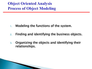
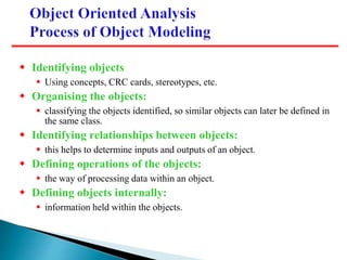
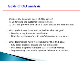
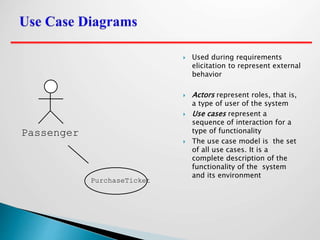
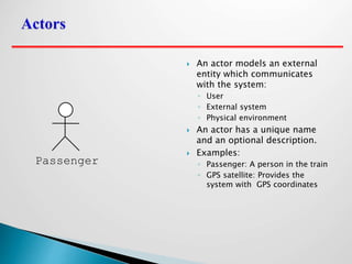
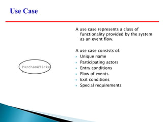
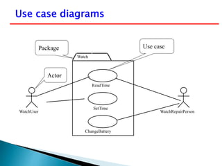
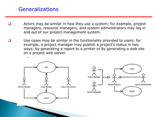
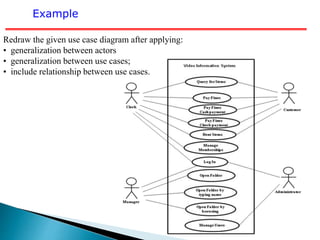
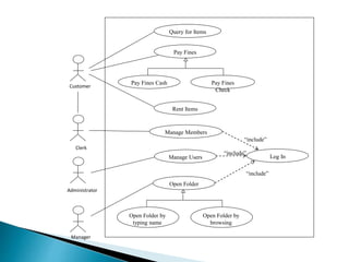
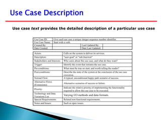
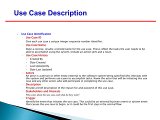
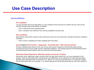
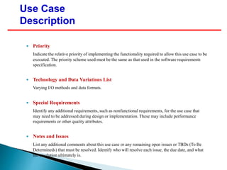
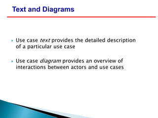
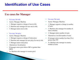
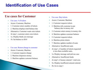
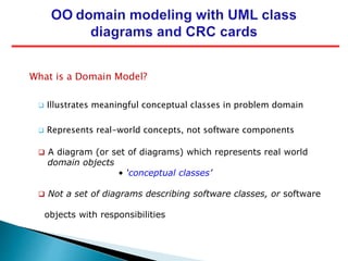
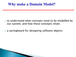
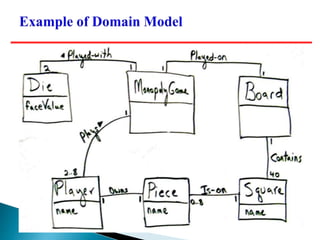
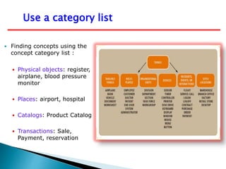
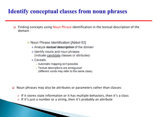
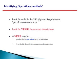
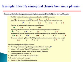
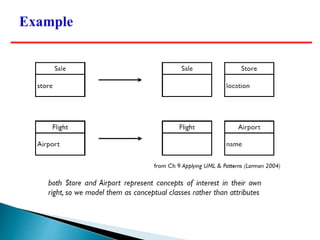
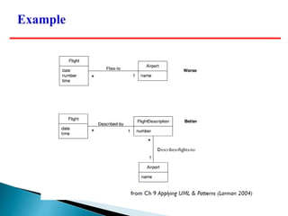
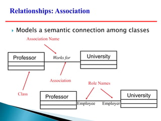
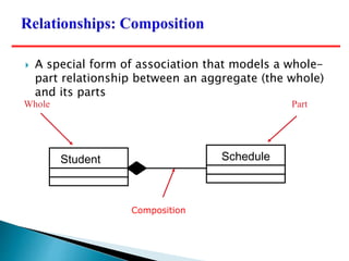
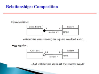
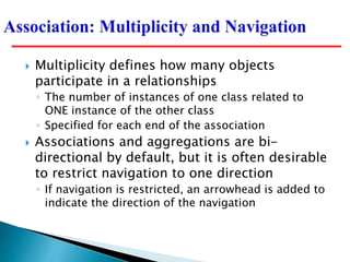
2. 1. Modeling the functions of the system.
2. Finding and identifying the business objects.
3. Organizing the objects and identifying their
relationships.
3. Identifying objects:
Using concepts, CRC cards, stereotypes, etc.
Organising the objects:
classifying the objects identified, so similar objects can later be defined in
the same class.
Identifying relationships between objects:
this helps to determine inputs and outputs of an object.
Defining operations of the objects:
the way of processing data within an object.
Defining objects internally:
information held within the objects.
4. What are the two main goals of OO analysis?
1) Understand the customer’s requirements
2) Describe problem domain as a set of classes and relationships
What techniques have we studied for the 1st goal?
◦ Develop a requirements specification
◦ Describe scenarios of use in user’s language as use cases
What techniques have we studied for the 2nd goal?
◦ CRC cards discover classes and run simulations
◦ UML class diagrams represent classes & relationships
◦ Sequence diagrams model dynamic behavior of a system
5. System analysis use case – a use case that documents the interaction
between the system user and the system. It is highly detailed in describing
what is required but is free of most implementation details and constraints.
1. Identify, define, and document new actors.
2. Identify, define, and document new use cases.
3. Identify any reuse possibilities.
4. Refine the use-case model diagram (if necessary).
5. Document system analysis use-case narratives.
6. Use Case Diagrams describe the functionality of a system and
users of the system.
Describe the functional behavior of the system as seen by the
user.
These diagrams contain the following elements:
• Actors, which represent users of a system, including human
users and other systems.
• Use Cases, which represent functionality or services provided
by a system to users.
7. To draw an use case diagram we should have the following items
identified. Functionalities to be represented as an use case
Actors Relationships among the use cases and actors.
Use case diagrams are considered for high level requirement
analysis of a system. So when the requirements of a system
are analyzed the functionalities are captured in use cases.
8. Use case diagrams are drawn to capture the functional requirements
of a system. So after identifying the above items we have to follow
the following guidelines to draw an efficient use case diagram.
The name of a use case is very important. So the name should
be chosen in such a way so that it can identify the functionalities
performed.
Give a suitable name for actors. Show relationships and
dependencies clearly in the diagram.
Do not try to include all types of relationships.
Because the main purpose of the diagram is to identify
requirements.
Use note when ever required to clarify some important
points.
9. Used during requirements
elicitation to represent external
behavior
Actors represent roles, that is,
a type of user of the system
Use cases represent a
sequence of interaction for a
type of functionality
The use case model is the set
of all use cases. It is a
complete description of the
functionality of the system
and its environment
Passenger
PurchaseTicket
10. An actor models an external
entity which communicates
with the system:
◦ User
◦ External system
◦ Physical environment
An actor has a unique name
and an optional description.
Examples:
◦ Passenger: A person in the train
◦ GPS satellite: Provides the
system with GPS coordinates
Passenger
11. A use case represents a class of
functionality provided by the system
as an event flow.
A use case consists of:
Unique name
Participating actors
Entry conditions
Flow of events
Exit conditions
Special requirements
PurchaseTicke
t
13. Example: High Level Use Case Diagram
Manage Resources
Manage Projects
System Admin
Resource Manager
Project Manager
System Administrator
14. Example: Managing Resources Use Case Diagram
Add Skill
Remove
Skill
Update
Skill
Find Skill
Add
Resource
Remove
Resource
Update
Resource
Find
Resource
Unassign
Skill from
Resource
Assign Skill
from
Resource
Resource Manager
15. The following is a sample use case diagram representing the order
management system. So if we look into the diagram then we will find
three use cases (Order, SpecialOrder and NormalOrder) and one actor
which is customer.
The SpecialOrder and NormalOrder use cases are extended from Order use
case. So they have extends relationship.
Example: Order management system
16. Dependences
Include Dependencies
Extend Dependencies
An include dependency from one
use case (called the base use
case) to another use case (called
the inclusion use case) indicates
that the base use case will include
or call the inclusion use case. A
use case may include multiple use
cases, and it may be included in
multiple use cases.
An extend dependency from one use
case (called the extension use case)
to another use case (called the base
use case) indicates that the extension
use case will extend (or be inserted
into) and augment the base use case.
A use case may extend multiple use
cases, and a use case may be
extended by multiple use cases.
A
B
A
B
17. Generalizations
Actors may be similar in how they use a system; for example, project
managers, resource managers, and system administrators may log in
and out of our project management system.
Use cases may be similar in the functionality provided to users; for
example, a project manager may publish a project's status in two
ways: by generating a report to a printer or by generating a web site
on a project web server.
18. Redraw the given use case diagram after applying:
• generalization between actors
• generalization between use cases;
• include relationship between use cases.
Example
19. Query for Items
Rent Items
Pay Fines
Pay Fines Cash Pay Fines
Check
Open Folder
Open Folder by
typing name
Open Folder by
browsing
Manage Members
Manage Users Log In
Customer
Clerk
Administrator
Manager
“include”
“include”
“include”
20. Use case text provides the detailed description of a particular use case
Use Case ID: Give each use case a unique integer sequence number identifier.
Use Case Name: Start with a verb.
Created By: Last Updated By:
Date Created: Date Last Updated:
Actors: Calls on the system to deliver its services.
Description: "user-goal" or "sub-function"
Stakeholders and Interests: Who cares about this use case, and what do they want?
Trigger: Identify the event that initiates the use case.
Pre-conditions: What must be true on start, and worth telling the reader?
Post-conditions: Describe the state of the system at the conclusion of the use case
execution.
Normal Flow: A typical, unconditional happy path scenario of success.
Alternative Flows
(Extensions):
Alternative scenarios of success or failure.
Priority:
Indicate the relative priority of implementing the functionality
required to allow this use case to be executed.
Technology and Data
Variations List
Varying I/O methods and data formats.
Special Requirements: Related non-functional requirements.
Notes and Issues: Such as open issues.
Use Case Description
21. Use Case Identification
◦ Use Case ID
Give each use case a unique integer sequence number identifier.
◦ Use Case Name
State a concise, results-oriented name for the use case. These reflect the tasks the user needs to be
able to accomplish using the system. Include an action verb and a noun.
◦ Use Case History
Created By
Date Created
Last Updated By
Date Last Updated
◦ Actors
An actor is a person or other entity external to the software system being specified who interacts with
the system and performs use cases to accomplish tasks. Name the actor that will be initiating this use
case and any other actors who will participate in completing the use case.
◦ Description
Provide a brief description of the reason for and outcome of this use case.
◦ Stakeholders and Interests
Who cares about this use case, and what do they want?
◦ Trigger
Identify the event that initiates the use case. This could be an external business event or system event
that causes the use case to begin, or it could be the first step in the normal flow.
Use Case Description
22. Use Case Definition
◦ Pre-conditions
List any activities that must take place, or any conditions that must be true, before the use case can be
started. Number each precondition. Examples:
User’s identity has been authenticated.
User’s computer has sufficient free memory available to launch task.
◦ Post-conditions
Describe the state of the system at the conclusion of the use case execution. Number each post-condition.
Examples:
Price of item in database has been updated with new value.
◦ Normal (basic) Flow of events – Happy path - Successful path – Main Success Scenario
Provide a detailed description of the user actions and system responses that will take place during
execution of the use case under normal, expected conditions. This dialog sequence will ultimately lead to
accomplishing the goal stated in the use case name and description.
◦ Alternative Flows (Extensions): Alternate scenarios of success or failure
Document other, legitimate usage scenarios that can take place within this use case separately in this
section. State the alternative flow, and describe any differences in the sequence of steps that take place.
Number each alternative flow in the form “X.Y”, where “X” is the Use Case ID and Y is a sequence number
for the alternative flow. For example, “5.3” would indicate the third alternative flow for use case number 5.
Use Case Description
23. Priority
Indicate the relative priority of implementing the functionality required to allow this use case to be
executed. The priority scheme used must be the same as that used in the software requirements
specification.
Technology and Data Variations List
Varying I/O methods and data formats.
Special Requirements
Identify any additional requirements, such as nonfunctional requirements, for the use case that
may need to be addressed during design or implementation. These may include performance
requirements or other quality attributes.
Notes and Issues
List any additional comments about this use case or any remaining open issues or TBDs (To Be
Determineds) that must be resolved. Identify who will resolve each issue, the due date, and what
the resolution ultimately is.
Use Case
Description
24. Use case text provides the detailed description
of a particular use case
Use case diagram provides an overview of
interactions between actors and use cases
25. The ClubRiyadh Sport has decided to implement an electronic card system for its subscriber, so that
subscribers can use their K-cards to access secure areas, and also as a debit card, linked to an account
into which subscribers can deposit money to be used to pay club fees. For the initial release of the
system, this will be limited to a few club usages: equipment rental at the sports centre, beverage fees,
and library fees at club libraries. The system will keep a usage record for each K-card.
Identify use cases by providing the actors, use case names. Draw the use case diagram.
27. I am the manager of a theatre.
I want to create an automated movie ticket machine.
You are analysts who need to describe
what the customer wants as a set of use cases
Simplifying assumptions:
◦ One movie showing at a time
◦ Movie time is same every day, only one time, same price
◦ Only manager can change/add movie
◦ Customer can only buy tickets
Who or what are the actors?
What are the use cases (goals of actors)?
Use case diagram for Movie Ticket Machine
28. Use case diagram for Movie Ticket Machine
# of tickets
Set title
Buy tickets
Give change
Set price
Customer
Manager
Set seats
Movie Ticket Machine
29. Use case: Set title
Actors: Manager, Machine
1. Manager requests a change of movie title
2. Machine asks manager for new movie title
3. Manager enters movie title
Use case: Set price
Actors: Manager, Machine
1. Manager requests a change of ticket price
2. Machine asks manager for new price for movie title
3. Manager enters ticket price
Alternatives: Invalid price
If manager enters price below SR5 or greater than
SR50
3a. Machine asks manager to reenter price
Use case: Set seats
Actors: Manager, Machine
1. Manager requests a change in number
of seats
2. Machine asks manager for number of
seats in theatre
3. Manager enters number of seats
Alternatives: Invalid number of seats
If manager enters number less than 20 or
greater than 999
3a. Machine asks manager to reenter
number of seats
Identification of Use Cases
30. Use case: # of tickets
Actors: Customer, Machine
1. Customer enters number of tickets
2. Machine displays total balance due
Alternative: Customer wants zero tickets
At step 1, customer enters zero tickets
1a. Display thank you message
1b. Set balance to $0.0
Use case: Return change to customer
Actors: Customer, Machine
1. Customer requests change
2. Machine dispenses money
3. Machine updates customer balance
Use case: Buy tickets
Actors: Customer, Machine
1. Customer requests tickets
2. Machine tells customer to put
balance due in money slot
3. Customer enters money in money slot
4. Machine updates customer balance
5. Customer requests tickets
6. Machine prints tickets
7. Machine updates number of seats
Alternative: Insufficient seats
At step 1, if number of tickets requested
is less than available seats,
1a. Display message and end use case
Alternative: Insufficient funds
At step 5, if money entered < total cost,
5a. Display insufficient amount entered
5b. Go to step 3
Identification of Use Cases
31. What is a Domain Model?
Illustrates meaningful conceptual classes in problem domain
Represents real-world concepts, not software components
A diagram (or set of diagrams) which represents real world
domain objects
• ‘conceptual classes’
Not a set of diagrams describing software classes, or software
objects with responsibilities
32. to understand what concepts need to be modelled by
our system, and how those concepts relate
a springboard for designing software objects
33. conceptual classes
associations between conceptual classes
attributes of conceptual classes
34. A useful strategy for building a domain model is to start with:
the “boundary” concepts that interact directly with the actors
and then identify the internal concepts
Building the Domain Model
35. Identify Candidate Conceptual classes
Draw them in a Domain Model
Add associations necessary to record the relationships that
must be retained
Add attributes necessary for information to be preserved
36.
37.
38. Use a category list
Finding concepts using the
concept category list :
Physical objects: register,
airplane, blood pressure
monitor
Places: airport, hospital
Catalogs: Product Catalog
Transactions: Sale,
Payment, reservation
39. Noun phrases may also be attributes or parameters rather than classes:
If it stores state information or it has multiple behaviors, then it’s a class
If it’s just a number or a string, then it’s probably an attribute
Finding concepts using Noun Phrase identification in the textual description of the
domain :
44. sometimes we need to separate out the description
of a concept from the concept itself, so that even if
no instances of the concept exist at a given point in
time, its description will still be present in the
system.
doing this can reduce unnecessary redundancy in
recording information when we move into design
and build.
45.
46.
47. Professor
name
empID
create( )
save( )
delete( )
change( )
Class Name
Attributes
Operations
A class is comprised of three sections
◦ The first section contains the class name
◦ The second section shows the structure (attributes)
◦ The third section shows the behavior (operations)
58. Multiplicity defines how many objects
participate in a relationships
◦ The number of instances of one class related to
ONE instance of the other class
◦ Specified for each end of the association
Associations and aggregations are bi-
directional by default, but it is often desirable
to restrict navigation to one direction
◦ If navigation is restricted, an arrowhead is added to
indicate the direction of the navigation
59.
60. Multiplicity – the
minimum and
maximum number of
occurrences of one
object/class for a
single occurrence of
the related object/class.
63. A relationship among classes where one class
shares the structure and/or behavior of one or
more classes
Defines a hierarchy of abstractions in which a
subclass inherits from one or more superclasses
◦ Single inheritance
◦ Multiple inheritance
Generalization is an “is-a-kind of” relationship
64.
65. Airplane Helicopter Wolf Horse
FlyingThing Animal
Bird
multiple
inheritance
Use multiple inheritance only when needed, and
always with caution !
A class can inherit from several other classes
66. Inheritance leverages the similarities among classes
A subclass inherits its parent’s attributes,
operations, and relationships
A subclass may:
◦ Add additional attributes, operations, relationships
◦ Redefine inherited operations (use caution!)
Common attributes, operations, and/or
relationships are shown at the highest applicable
level in the hierarchy
67. we should model the important relationships
between conceptual classes
◦ not every relationship, that would create clutter
and confusion
◦ not too few, we want a useful model
for each association, provide:
◦ a short yet meaningful text label
◦ the multiplicity
69. Consider the world of libraries. A library has books, videos, and CDs that
it loans to its users. All library material has a id# and a title. In addition,
books have one or more authors, videos have one producer and one or
more actors, while CDs have one or more entertainers. The library
maintains one or more copies of each library item (book, video or CD).
Copies of all library material can be loaned to users. Reference-only
material is loaned for 2hrs and can’t be removed from the library. Other
material can be loaned for 2 weeks. For every loan, the library records
the user, the loan date and time, and the return date and time. For
users, the library maintains their name, address and phone number.
Define the two main actors.
Identify use cases by providing the actors, use case names. Draw the us
e case diagram.
Create the conceptual class diagram.
Example: Library System
70. Draw a UML Class Diagram representing the following elements from
the problem domain for digital music players: An artist is either a band
or a musician, where a band consists of two or more musicians. Each
song has an artist who wrote it, and an artist who performed it, and a
title. Therefore, each song is performed by exactly one artist, and
written by exactly one artist. An album is composed of a number of
tracks, each of which contains exactly one song. A song can be used in
any number of tracks, because it could appear on more than one album
(or even more than once on the same album!). A track has bitrate and
duration. Because the order of the tracks on an album is important, the
system will need to know, for any given track, what the next track is,
and what the previous track is.
Draw a class diagram for this information, and be sure to label all
the associations (relationships) with appropriate multiplicities.
71. Applying UML & Patterns (Larman 2007),
Chapters 6, 9.
Object-Oriented Systems Analysis and Design
(Bennett et al, Third Edition, 2006), Chapter
6, 7.