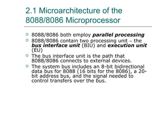
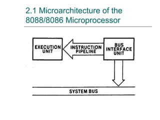
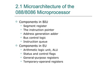
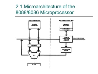
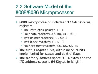
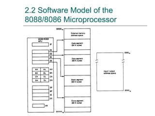
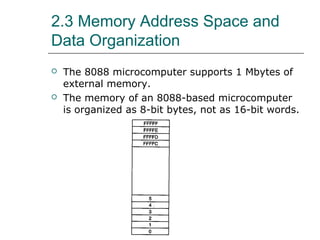
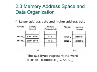
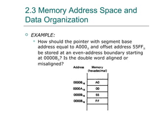
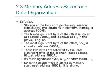
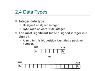
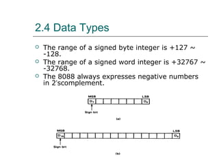
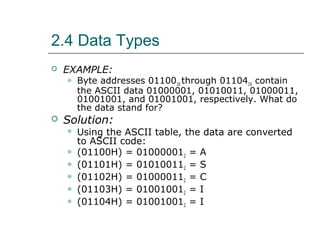
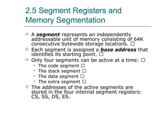
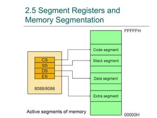
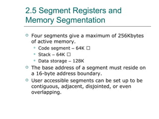
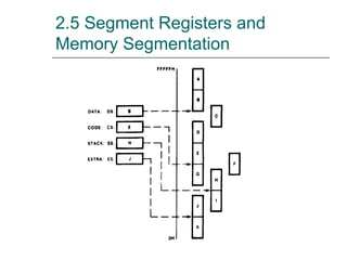
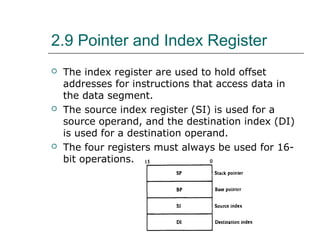
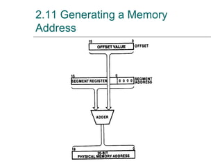
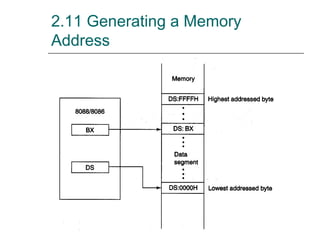
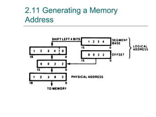
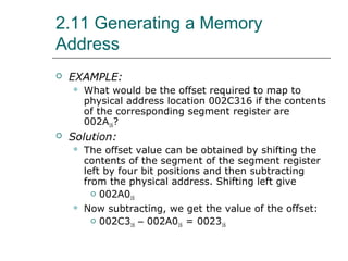
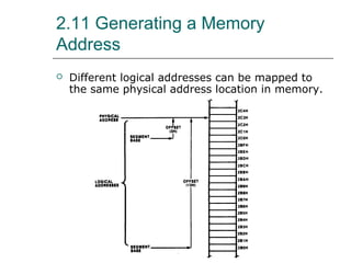
This document describes the software architecture of the Intel 8088 and 8086 microprocessors. It covers topics such as the microarchitecture, memory addressing, registers, data types, segmentation, the stack, and input/output. The 8088/8086 use segmentation to access up to 1MB of memory using segment registers and offsets. They contain various registers for data, pointers, indexes, and status flags. Memory is addressed by combining a segment base with an offset to generate a physical address.
In these slides the registration organization and stack organization have discussed in detail. Stack organization is discussed with the aid of animation to let the user understand it in a better and easy way.
Register Organization of 8086, Architecture, Signal Description of 8086, Physical Memory
Organization, General Bus Operation, I/O Addressing Capability, Special Processor Activities,
Minimum Mode 8086 System and Timings, Maximum Mode 8086 System and Timings.
Addressing Modes of 8086.
2. SOFTWARE ARCHITECTURE OF
THE 8088 AND 8086
MICROPROCESSORS
2.1 Microarchitecture of the 8088/8086
Microprocessor
2.2 Software Model of the 8088/8086
Microprocessor
2.3 Memory Address Space and Data
Organization
2.4 Data Types
2.5 Segment Registers and Memory
Segmentation
2.6 Dedicated, Reserved, and General-Used
Memory
2.7 Instruction Pointer
3. SOFTWARE ARCHITECTURE OF
THE 8088 AND 8086
MICROPROCESSORS
2.8 Data Registers
2.9 Pointer and Index Register
2.10 Status Register
2.11 Generating a Memory Address
2.12 The Stack
2.13 Input/Output Address Space
4. 2.1 Microarchitecture of the
8088/8086 Microprocessor
8088/8086 both employ parallel processing
8088/8086 contain two processing unit – the
bus interface unit (BIU) and execution unit
(EU)
The bus interface unit is the path that
8088/8086 connects to external devices.
The system bus includes an 8-bit bidirectional
data bus for 8088 (16 bits for the 8086), a 20-
bit address bus, and the signal needed to
control transfers over the bus.
6. 2.1 Microarchitecture of the
088/8086 Microprocessor
Components in BIU
Segment register
The instruction pointer
Address generation adder
Bus control logic
Instruction queue
Components in EU
Arithmetic logic unit, ALU
Status and control flags
General-purpose registers
Temporary-operand registers
8. 2.2 Software Model of the
8088/8086 Microprocessor
8088 microprocessor includes 13 16-bit internal
registers.
The instruction pointer, IP �
Four data registers, AX, BX, CX, DX �
Two pointer registers, BP, SP �
Two index registers, SI, DI �
Four segment registers, CS, DS, SS, ES
The status register, SR, with nine of its bits
implemented for status and control flags.
The memory address space is 1 Mbytes and the
I/O address space is 64 Kbytes in length.
10. 2.3 Memory Address Space and
Data Organization
The 8088 microcomputer supports 1 Mbytes of
external memory.
The memory of an 8088-based microcomputer
is organized as 8-bit bytes, not as 16-bit words.
11. 2.3 Memory Address Space and
Data Organization
Lower address byte and higher address byte
The two bytes represent the word
01010101000000102 = 550216
12. 2.3 Memory Address Space and
Data Organization
EXAMPLE:
What is the data word shown in the previous
figure (b)? Express the result in hexadecimal
form. Is it stored at an even- or odd-addressed
word boundary? Is it an aligned or misaligned
word of data?
13. 2.3 Memory Address Space and
Data Organization
Solution:
111111012 = FD16 = FDH
101010102 = AA16 = AAH
Together the two bytes give the word
11111101101010102 = FDAA16 = FDAAH
Expressing the address of the least significant
byte in binary form gives
0072BH = 0072B16 = 000000000111001010112
Therefore, it is misaligned word of data.
14. 2.3 Memory Address Space and
Data Organization
Even- or odd-addressed
word
If the least significant
bit of the address is 0,
the word is said to be
held at an even-
addressed boundary.
Aligned word or
misaligned word
15. 2.3 Memory Address Space and
Data Organization
A double word corresponds to four
consecutive bytes of data stored in memory.
16. 2.3 Memory Address Space and
Data Organization
A pointer is a double word.
The higher address word represents the
segment base address
The lower address word represents the offset.
Example:
Segment base address = 3B4C16 = 00111011010011002
Offset value = 006516 = 00000000011001012
17. 2.3 Memory Address Space and
Data Organization
EXAMPLE:
How should the pointer with segment base
address equal to A00016 and offset address 55FF16
be stored at an even-address boundary starting
at 0000816? Is the double word aligned or
misaligned?
18. 2.3 Memory Address Space and
Data Organization
Solution:
Storage of the two-word pointer requires four
consecutive byte locations in memory, starting at
address 0000816.
The least-significant byte of the offset is stored
at address 0000816 and is shown as FF16 in the
previous figure.
The most significant byte of the offset, 5516, is
stored at address 0000916.
These two bytes are followed by the least
significant byte of the segment base address,
0016, at address 0000A16.
Its most significant byte, A016, at address 0000B16.
Since the double word is stored in memory
starting at address 0000816, it is aligned.
19. 2.4 Data Types
Integer data type
Unsigned or signed integer
Byte-wide or word-wide integer
The most significant bit of a signed integer is a
sign bit.
A zero in this bit position identifies a positive
number.
20. 2.4 Data Types
The range of a signed byte integer is +127 ~
-128.
The range of a signed word integer is +32767 ~
-32768.
The 8088 always expresses negative numbers
in 2’scomplement.
21. 2.4 Data Types
EXAMPLE:
A signed word integer equals FEFF16. What
decimal number does it represent?
Solution:
FEFF16 = 11111110111111112
The most significant bit is 1, the number is
negative and is in 2’s complement form.
Converting to its binary equivalent by subtracting
1 from the least significant bit
Then complement all bits give:
FEFF16 = -00000001000000012 = -257
22. 2.4 Data Types
The 8088 can also process data that is coded as
binary-coded decimal (BCD) numbers.
BCD data can be stored in packed or unpacked
forms.
23. 2.4 Data Types
EXAMPLE:
The packed BCD data stored at byte address
0100016 equals 100100012. What is the two digit
decimal number?
Solution:
Writing the value 100100012 as separate BCD
digits gives
100100012 = 1001BCD0001BCD = 9110
24. 2.4 Data Types
The ASCII
(American
Standard Code
for Information
Interchange)
digit
25. 2.4 Data Types
EXAMPLE:
Byte addresses 0110016 through 0110416 contain
the ASCII data 01000001, 01010011, 01000011,
01001001, and 01001001, respectively. What do
the data stand for?
Solution:
Using the ASCII table, the data are converted
to ASCII code:
(01100H) = 010000012 = A
(01101H) = 010100112 = S
(01102H) = 010000112 = C
(01103H) = 010010012 = I
(01104H) = 010010012 = I
26. 2.5 Segment Registers and
Memory Segmentation
A segment represents an independently
addressable unit of memory consisting of 64K
consecutive bytewide storage locations.
Each segment is assigned a base address that
identifies its starting point.
Only four segments can be active at a time:
The code segment
The stack segment
The data segment
The extra segment
The addresses of the active segments are
stored in the four internal segment registers:
CS, SS, DS, ES.
28. 2.5 Segment Registers and
Memory Segmentation
Four segments give a maximum of 256Kbytes
of active memory.
Code segment – 64K
Stack – 64K
Data storage – 128K
The base address of a segment must reside on
a 16-byte address boundary.
User accessible segments can be set up to be
contiguous, adjacent, disjointed, or even
overlapping.
30. 2.6 Dedicated, Reserved, and
General-Used Memory
The dedicated memory (0000016 ~ 0001316)
are used for storage of the pointers to 8088’s
internal interrupt service routines and
exceptions.
The reserved memory (0001416 ~ 0007F16) are
used for storage of the pointers to user-defined
interrupts.
The 128-byte dedicated and reserved memory
can contain 32 interrupt pointers.
The general-use memory (0008016 ~ FFFEF16)
stores data or instructions of the program.
The dedicated memory (FFFE016 ~ FFFEB16) are
used for hardware reset jump instruction.
32. 2.7 Instruction Pointer
The instruction pointer (IP) identifies the
location of the next word of instruction code to
be fetched from the current code segment of
memory.
The offset in IP is combined with the current
value in CS to generate the address of the
instruction code.
During normal operation, the 8088 fetches
instructions from the code segment of memory,
stores them in its instruction queue, and
executes them one after the other.
33. 2.8 Data Registers
Data registers are used for temporary storage
of frequently used intermediate results.
The contents of the data registers can be read,
loaded, or modified through software.
The four data registers are:
Accumulator register, A
Base register, B
Counter register, C
Data register, D
Each register can be accessed either as a whole
(16 bits) for word data or as 8-bit data for
byte-wide operation.
36. 2.9 Pointer and Index Register
The pointer registers and index registers are
used to store offset addresses.
Values held in the index registers are used to
reference data relative to the data segment or
extra segment.
The pointer registers are used to store offset
addresses of memory location relative to the
stack segment register.
Combining SP with the value in in SS (SS:SP)
results in a 20-bit address that points to the
top of the stack (TOS).
BP is used to access data within the stack
segment of memory.
It is commonly used to reference subroutine
parameters.
37. 2.9 Pointer and Index Register
The index register are used to hold offset
addresses for instructions that access data in
the data segment.
The source index register (SI) is used for a
source operand, and the destination index (DI)
is used for a destination operand.
The four registers must always be used for 16-
bit operations.
38. 2.10 Status Register
The status register, also called the flags
register, indicate conditions that are produced
as the result of executing an instruction.
Only nine bits of the register are implemented.
Six of these bits represent status flags
The other three bits represent control flags
The 8088 provides instructions within its
instruction set that are able to use these flags
to alter the sequence in which the program is
executed.
39. 2.10 Status Register
Status and control bits maintained in the flags
register
Generally Set and Tested Individually
9 1-bit flags in 8086; 7 are unused
40. 2.10 Status Register
Status flags indicate current processor status.
CF Carry Flag Arithmetic Carry/Borrow
OF Overflow Flag Arithmetic Overflow
ZF Zero Flag Zero Result; Equal
Compare
SF Sign Flag Negative Result; Non-
Equal Compare
PF Parity Flag Even Number of “1” bits
AF Auxiliary Carry Used with BCD
Arithmetic
41. 2.10 Status Register
Control flags influence the 8086 during execution
phase
DF Direction Flag Auto Increment/Decrement
used for “string operations”
IF Interrupt Flag Enables Interrupts
allows “fetch-execute” to be interrupted
TF Trap Flag Allows Single-Step
for debugging; causes interrupt after each op
42. 2.11 Generating a Memory
Address
A logical address in the 8088 microcomputer
system is described by a segment base and an
offset.
The physical addresses that are used to
access memory are 20 bits in length.
The generation of the physical address involves
combining a 16-bit offset value that is located
in the instruction pointer, a base pointer, an
index register, or a pointer register and a 16-bit
segment base value that is located in one of the
segment register.
46. 2.11 Generating a Memory
Address
EXAMPLE:
What would be the offset required to map to
physical address location 002C316 if the contents
of the corresponding segment register are
002A16?
Solution:
The offset value can be obtained by shifting the
contents of the segment of the segment register
left by four bit positions and then subtracting
from the physical address. Shifting left give
002A016
Now subtracting, we get the value of the offset:
002C316 – 002A016 = 002316
47. 2.11 Generating a Memory
Address
Different logical addresses can be mapped to
the same physical address location in memory.
48. 2.12 The Stack
The stack is implemented for temporary
storage of information such as data or
addresses.
The stack is 64KBytes long and is organized
from a software point of view as 32K words.
The contents of the SP and BP registers are
used as offsets into the stack segment memory
while the segment base value is in the SS
register.
49. 2.12 The Stack
Push instructions (PUSH) and pop instructions
(POP)
Top of the stack (TOS) and bottom of the
stack (BOS)
The 8088 can push word-wide data and
address information onto the stack from
registers or memory.
Many stacks can exist but only one is active at
a time.
53. 2.13 Input/Output Address Space
The 8088 has separate memory and
input/output (I/O) address space.
The I/O address space is the place where I/O
interfaces, such as printer and terminal ports,
are implemented.
The I/O address range is from 000016 to
FFFF16.
This represents 64KByte addresses.
The I/O addresses are 16 bits long
Each of these addresses corresponds to one
byte-wide I/O port.
Certain I/O instructions can only perform
operations to addresses 000016 thru 00FF16
(page 0).