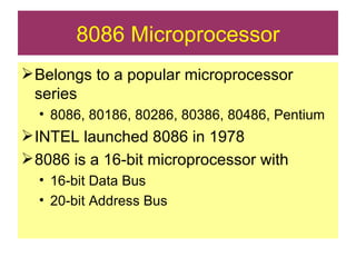
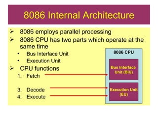
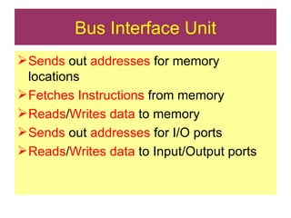
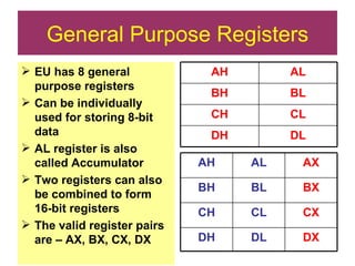
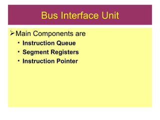
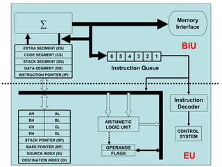
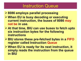
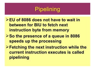
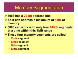
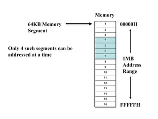
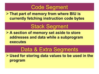
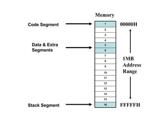
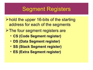
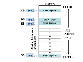
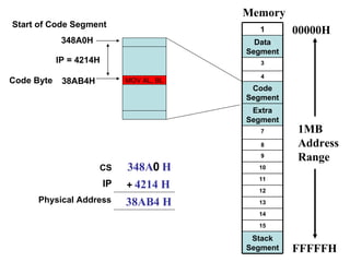
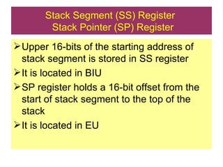
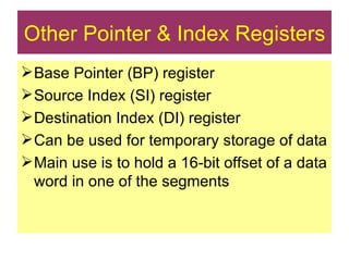
The document provides an introduction to the 8086 microprocessor. It describes how the 8086 is a 16-bit microprocessor that was launched by Intel in 1978. It discusses the internal architecture of the 8086, including how it employs parallel processing through separate bus interface and execution units to improve performance. It also describes the various registers and memory segmentation used in the 8086 architecture.
8086 Microprocessor Belongsto a popular microprocessor series 8086, 80186, 80286, 80386, 80486, Pentium INTEL launched 8086 in 1978 8086 is a 16-bit microprocessor with 16-bit Data Bus 20-bit Address Bus
3.
8086 Internal Architecture8086 employs parallel processing 8086 CPU has two parts which operate at the same time Bus Interface Unit Execution Unit CPU functions Fetch Decode Execute 8086 CPU Bus Interface Unit (BIU) Execution Unit (EU)
4.
Bus Interface UnitSends out addresses for memory locations Fetches Instructions from memory Reads / Writes data to memory Sends out addresses for I/O ports Reads / Writes data to Input/Output ports
5.
Execution Unit TellsBIU (addresses) where to fetch instructions or data Decodes & Executes instructions Dividing the work between BIU & EU speeds up processing
CONTROL SYSTEMARITHMETIC LOGIC UNIT FLAGS Instruction Queue OPERANDS ∑ Memory Interface EU BIU Instruction Decoder DESTINATION INDEX (DI) SOURCE INDEX (SI) BASE POINTER (BP) STACK POINTER (SP) DL DH CL CH BL BH AL AH EXTRA SEGMENT (ES) INSTRUCTION POINTER (IP) DATA SEGMENT (DS) STACK SEGMENT (SS) CODE SEGMENT (CS) 6 5 4 3 2 1
8.
Execution Unit Maincomponents are Instruction Decoder Control System Arithmetic Logic Unit General Purpose Registers Flag Register Pointer & Index registers
9.
Instruction Decoder Translatesinstructions fetched from memory into a series of actions which EU carries out Control System Generates timing and control signals to perform the internal operations of the microprocessor Arithmetic Logic Unit EU has a 16-bit ALU which can ADD, SUBTRACT, AND, OR, increment, decrement, complement or shift binary numbers
10.
General Purpose RegistersEU has 8 general purpose registers Can be individually used for storing 8-bit data AL register is also called Accumulator Two registers can also be combined to form 16-bit registers The valid register pairs are – AX, BX, CX, DX DL DH CL CH BL BH AL AH DL CL BL AL DX DH CX CH BX BH AX AH
11.
Flag Register 8086has a 16-bit flag register Contains 9 active flags There are two types of flags in 8086 Conditional flags – six flags, set or reset by EU on the basis of results of some arithmetic operations Control flags – three flags, used to control certain operations of the processor
12.
Flag Register CFU PF U AF U ZF SF TF IF DF OF U U U U DIRECTION FLAG DF 9. INTERRUPT FLAG IF 8. Control Flags TRAP FLAG TF 7. OVERFLOW FLAG OF 6. SIGN FLAG SF 5. ZERO FLAG ZF 4. AUXILIARY CARRY AF 3. PARITY FLAG PF 2. Conditional Flags (Compatible with 8085, except OF) CARRY FLAG CF 1.
13.
Bus Interface UnitMain Components are Instruction Queue Segment Registers Instruction Pointer
14.
CONTROL SYSTEMARITHMETIC LOGIC UNIT FLAGS Instruction Queue OPERANDS ∑ Memory Interface EU BIU Instruction Decoder DESTINATION INDEX (DI) SOURCE INDEX (SI) BASE POINTER (BP) STACK POINTER (SP) DL DH CL CH BL BH AL AH EXTRA SEGMENT (ES) INSTRUCTION POINTER (IP) DATA SEGMENT (DS) STACK SEGMENT (SS) CODE SEGMENT (CS) 6 5 4 3 2 1
15.
Instruction Queue 8086employs parallel processing When EU is busy decoding or executing current instruction, the buses of 8086 may not be in use. At that time, BIU can use buses to fetch upto six instruction bytes for the following instructions BIU stores these pre-fetched bytes in a FIFO register called Instruction Queue When EU is ready for its next instruction, it simply reads the instruction from the queue in BIU
16.
Pipelining EU of8086 does not have to wait in between for BIU to fetch next instruction byte from memory So the presence of a queue in 8086 speeds up the processing Fetching the next instruction while the current instruction executes is called pipelining
17.
Memory Segmentation 8086has a 20-bit address bus So it can address a maximum of 1MB of memory 8086 can work with only four 64KB segments at a time within this 1MB range These four memory segments are called Code segment Stack segment Data segment Extra segment
18.
Memory 00000H FFFFFH1MB Address Range 64KB Memory Segment Only 4 such segments can be addressed at a time 16 15 14 13 12 11 10 9 8 7 6 5 4 3 2 1 7 6 5 4
19.
Code Segment Thatpart of memory from where BIU is currently fetching instruction code bytes Stack Segment A section of memory set aside to store addresses and data while a subprogram executes Data & Extra Segments Used for storing data values to be used in the program
20.
Memory 00000H FFFFFH1MB Address Range Code Segment Stack Segment Data & Extra Segments 16 15 14 13 12 11 10 9 8 7 6 5 4 3 2 1
21.
Segment Registers holdthe upper 16-bits of the starting address for each of the segments The four segment registers are CS (Code Segment register) DS (Data Segment register) SS (Stack Segment register) ES (Extra Segment register)
22.
Memory 00000H FFFFFH1MB Address Range Starting Addresses of Segments 1000 0H 4000 0H 5000 0H F000 0H CS DS ES SS Stack Segment 15 14 13 12 11 10 9 8 7 Extra Segment Data Segment 4 3 Code Segment 1
23.
Address of asegment is of 20-bits A segment register stores only upper 16-bits BIU always inserts zeros for the lowest 4-bits of the 20-bit starting address. E.g. if CS = 348AH, then the code segment will start at 348A0H A 64-KB segment can be located anywhere in the memory, but will start at an address with zeros in the lowest 4-bits
24.
Instruction Pointer (IP)Register a 16-bit register Holds 16-bit offset , of the next instruction byte in the code segment BIU uses IP and CS registers to generate the 20-bit address of the instruction to be fetched from memory
25.
Memory 00000H FFFFFH1MB Address Range 348A H 4214 H 38AB4 H CS IP Physical Address Start of Code Segment 348A0H Code Byte MOV AL, BL 38AB4H IP = 4214H + 0 Stack Segment 15 14 13 12 11 10 9 8 7 Extra Segment Code Segment 4 3 Data Segment 1
26.
Stack Segment (SS)Register Stack Pointer (SP) Register Upper 16-bits of the starting address of stack segment is stored in SS register It is located in BIU SP register holds a 16-bit offset from the start of stack segment to the top of the stack It is located in EU
27.
Other Pointer &Index Registers Base Pointer (BP) register Source Index (SI) register Destination Index (DI) register Can be used for temporary storage of data Main use is to hold a 16-bit offset of a data word in one of the segments