Downloaded 52 times


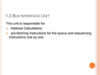
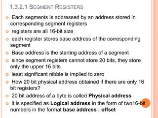
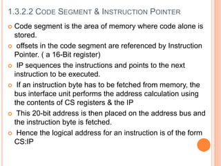
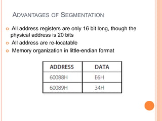
![ Here, either the source or the destination will be a memory address
MOV AX, [2345H] ; move word location 2345H to AX
MOV [1089H], AL ; the byte in AL is moved to location 1086H
MOV AX , PRICE
MOV COST,AL
PRICE and COST are labels for memory addresses
1.4.3 DIRECT ADDRESSING](https://image.slidesharecdn.com/chapter1archietectureof8086-170612061526/85/Chapter-1-archietecture-of-8086-21-320.jpg)
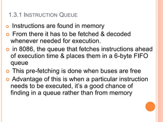
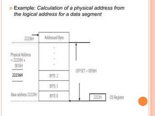
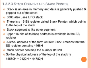
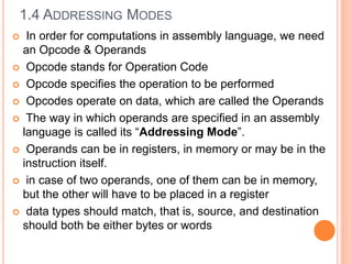
![1.4.4REGISTER INDIRECT ADDRESSING
In this mode , the address of the data is held in a register
Effective address
EA=EA= { [BX] / [DI] /[SI]}
MOV AL,[BX] ; move into AL the content of the location
whose address is in BX
MOV [SI], CL ;move the content of CL to the address
pointed by SI
MOV [DI],AX ; move the content of AX to the address
pointed by DI
In third instruction, AX contains two bytes, so the content
of AL will be moved to the address pointed by DI.
The content of AH will be moved to the address [D+1]](https://image.slidesharecdn.com/chapter1archietectureof8086-170612061526/85/Chapter-1-archietecture-of-8086-22-320.jpg)
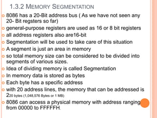
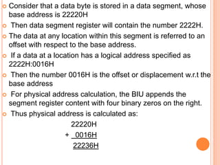
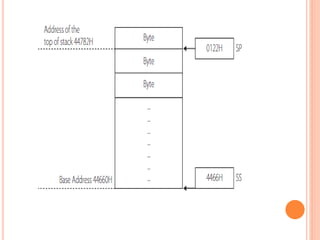
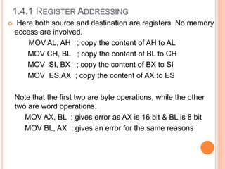
![ Show the location of data in memory, after the
execution of each of these instructions , if the
content of registers are as given
DS= 1112H , AX= EE78H and BX=3400H
MOV [0422H], AL
MOV [0424H],AX
MOV [BX] ,AX
EXAMPLE](https://image.slidesharecdn.com/chapter1archietectureof8086-170612061526/85/Chapter-1-archietecture-of-8086-23-320.jpg)
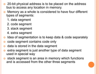
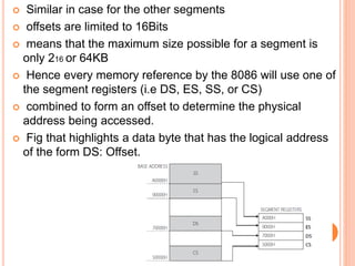
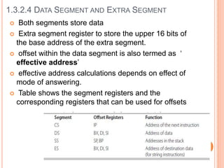
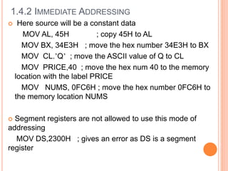
![1.4.5 REGISTER RELATIVE ADDRESSING
In relative addressing mode , a number or
displacement is part of the effective address
EA ={[BX] /[DI] /[SI] /[BP]} + 8 bit or 16 bit displacement
The displacement can be a 16 bit signed/unsigned
number or an 8 bit sign extended number.
MOV CL ,10[BX] ; move the content of the address
specified by adding the content of BX and 10
Like
MOV CL, [BX+10]
MOV CL, [BX]+10](https://image.slidesharecdn.com/chapter1archietectureof8086-170612061526/85/Chapter-1-archietecture-of-8086-24-320.jpg)
![1.4.6 BASED INDEXED MODE
In this mode ,an index register and a base register
together carry the effective address .
The content of these two registers are added and called
the effective address.
MOV AL,[BX][SI] ; move the content of the effective
address pointed by [BX] and [SI] into AL
MOV [BX][DI],CX ;move the content of CX to the effective
address pointed by [BX] and [SI]](https://image.slidesharecdn.com/chapter1archietectureof8086-170612061526/85/Chapter-1-archietecture-of-8086-25-320.jpg)
![1.4.7 RELATIVE BASED INDEXED MODE
The ‘effective address is the sum of the two registers
and a displacement .
MOV DL ,5[BX][DI]
MOV 5[BP][SI], AX
MOV CL ,COST[BX[[SI]](https://image.slidesharecdn.com/chapter1archietectureof8086-170612061526/85/Chapter-1-archietecture-of-8086-26-320.jpg)
![EXAMPLE
Find the address of physical memory for the
following instructions if the content of the
required registers are as given below
SS =2344 H, DS =4022H ,
BX =0200H,BP=1402H ,SI=4442H
i)MOV CL,1234H[SI]
i)MOV AL,5[SI[[BP]](https://image.slidesharecdn.com/chapter1archietectureof8086-170612061526/85/Chapter-1-archietecture-of-8086-27-320.jpg)

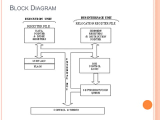
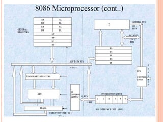
The document discusses the architecture of the 8086 microprocessor. It describes the 8086 as a 16-bit processor that can access external memory using a 20-bit address bus. The 8086 uses memory segmentation to map the larger 20-bit physical addresses to the smaller 16-bit registers. Each segment is defined by a base address stored in a 16-bit segment register. The 20-bit physical address is calculated by combining the segment register value and offset. The document provides details on the various memory segments and addressing modes supported by the 8086 architecture.