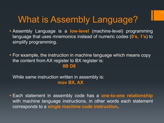
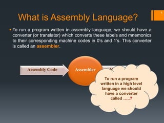
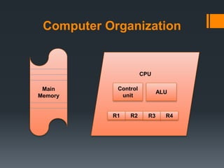
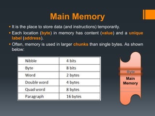
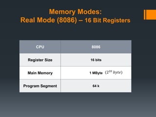
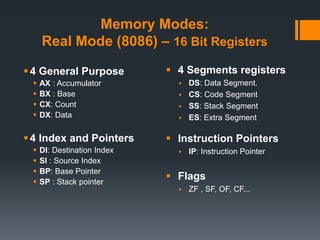
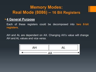
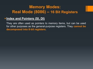
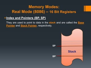
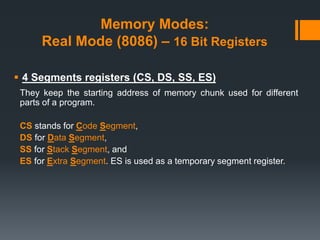
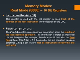
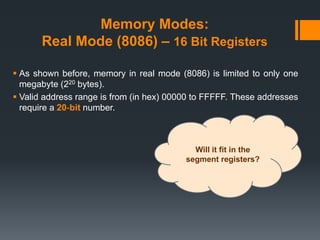
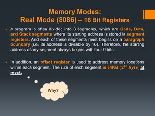
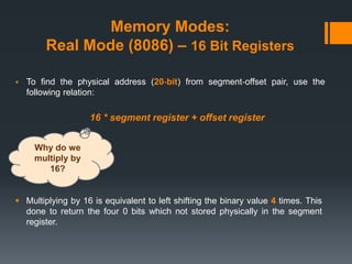
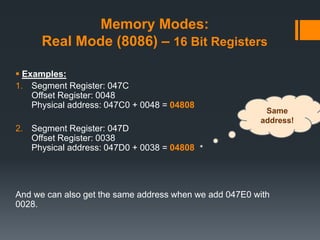
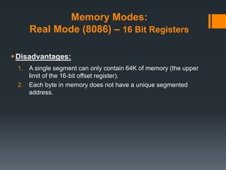
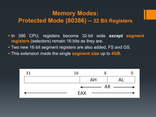
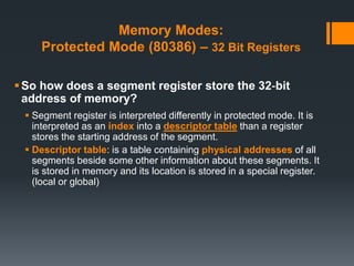
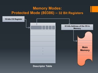
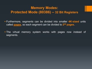
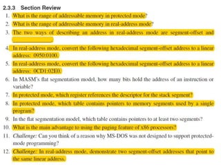
Assembly Language - Lab (2)
1
Agenda
What is Assembly Language?
Computer Organization
Main memory
Memory Modes:
 Real Mode (8086)
 Protected Mode (80386)
What is Assembly Language?
 Assembly Language is a low-level (machine‐level) programming
language that uses mnemonics instead of numeric codes (0’s, 1’s) to
simplify programming.
 For example, the instruction in machine language which means copy
the content from AX register to BX register is:
8B D8
While same instruction written in assembly is:
mov BX, AX
 Each statement in assembly code has a one-to-one relationship
with machine language instructions, in other words each statement
corresponds to a single machine code instruction.
3
 To run a program written in assembly language, we should have a
converter (or translator) which converts these labels and mnemonics
to their corresponding machine codes in 0’s and 1’s. This converter
is called an assembler.
4
Machine CodeAssemblerAssembly Code
To run a program
written in a high level
language we should
have a converter
called …..?
What is Assembly Language?
Computer Organization
Main
Memory
CPU
R2 R3R1
ALU
Control
unit
R4
Main Memory
 It is the place to store data (and instructions) temporarily.
 Each location (byte) in memory has content (value) and a unique
label (address).
 Often, memory is used in larger chunks than single bytes. As shown
below:
Main
Memory
Byte
Memory Modes:
Real Mode (8086) – 16 Bit Registers
CPU 8086
Register Size 16 bits
Main Memory 1 MByte
Program Segment 64 k
(220 𝑏𝑦𝑡𝑒)
Memory Modes:
Real Mode (8086) – 16 Bit Registers
4 General Purpose
 AX : Accumulator
 BX : Base
 CX: Count
 DX: Data
4 Index and Pointers
 DI: Destination Index
 SI : Source Index
 BP: Base Pointer
 SP : Stack pointer
 4 Segments registers
 DS: Data Segment.
 CS: Code Segment
 SS: Stack Segment
 ES: Extra Segment
 Instruction Pointers
 IP: Instruction Pointer
 Flags
 ZF , SF, OF, CF...
Memory Modes:
Real Mode (8086) – 16 Bit Registers
4 General Purpose
Each of these registers could be decomposed into two 8‐bit
registers.
AH and AL are dependent on AX. Changing AX’s value will change
AH and AL values and vice versa.
Memory Modes:
Real Mode (8086) – 16 Bit Registers
Index and Pointers (SI, DI)
They are often used as pointers to memory items, but can be used
for other purposes as the general‐purpose registers. They cannot be
decomposed into 8‐bit registers.
Memory Modes:
Real Mode (8086) – 16 Bit Registers
Index and Pointers (BP, SP)
They are used to point to data in the stack and are called the Base
Pointer and Stack Pointer, respectively.
Stack
BP
SP
Memory Modes:
Real Mode (8086) – 16 Bit Registers
 4 Segments registers (CS, DS, SS, ES)
They keep the starting address of memory chunk used for different
parts of a program.
CS stands for Code Segment,
DS for Data Segment,
SS for Stack Segment, and
ES for Extra Segment. ES is used as a temporary segment register.
Memory Modes:
Real Mode (8086) – 16 Bit Registers
 Instruction Pointers (IP)
This register is used with the CS register to keep track of the
address of the next instruction to be executed by the CPU.
 Flags (ZF , SF, OF, CF...)
The FLAGS register stores important information about the results of
the last executed operation. This information is stored as individual
bits in this register. For example, there is a specific bit called the Zero
flag (Z flag). This Z flag is 1 if the result of the last operation was zero
otherwise Z flag is set to zero. Not all instructions modify the bits
in FLAGS.
Memory Modes:
Real Mode (8086) – 16 Bit Registers
 As shown before, memory in real mode (8086) is limited to only one
megabyte (220 bytes).
 Valid address range is from (in hex) 00000 to FFFFF. These addresses
require a 20‐bit number.
Will it fit in the
segment registers?
Memory Modes:
Real Mode (8086) – 16 Bit Registers
 A program is often divided into 3 segments, which are Code, Data,
and Stack segments where its starting address is stored in segment
registers. And each of these segments must begins on a paragraph
boundary (i.e. its address is divisible by 16). Therefore, the starting
address of any segment always begins with four 0‐bits.
 In addition, an offset register is used to address memory locations
within each segment. The size of each segment is 64KB (𝟐 𝟏𝟔 𝒃𝒚𝒕𝒆) at
most.
Why?
Memory Modes:
Real Mode (8086) – 16 Bit Registers
 To find the physical address (20‐bit) from segment‐offset pair, use the
following relation:
16 * segment register + offset register
 Multiplying by 16 is equivalent to left shifting the binary value 4 times. This
done to return the four 0 bits which not stored physically in the segment
register.
Why do we
multiply by
16?
Memory Modes:
Real Mode (8086) – 16 Bit Registers
 Examples:
1. Segment Register: 047C
Offset Register: 0048
Physical address: 047C0 + 0048 = 04808
2. Segment Register: 047D
Offset Register: 0038
Physical address: 047D0 + 0038 = 04808
And we can also get the same address when we add 047E0 with
0028.
Same
address!
Memory Modes:
Real Mode (8086) – 16 Bit Registers
Disadvantages:
1. A single segment can only contain 64K of memory (the upper
limit of the 16‐bit offset register).
2. Each byte in memory does not have a unique segmented
address.
Memory Modes:
Protected Mode (80386) – 32 Bit Registers
CPU 80386
Register Size 32 bits
Main Memory 4 Gbyte
Program Segment 4 Gbyte
(232 𝑏𝑦𝑡𝑒)
Memory Modes:
Protected Mode (80386) – 32 Bit Registers
 In 386 CPU, registers become 32‐bit wide except segment
registers (selectors) remain 16‐bits as they are.
 Two new 16‐bit segment registers are also added, FS and GS.
 This extension made the single segment size up to 4GB.
Memory Modes:
Protected Mode (80386) – 32 Bit Registers
So how does a segment register store the 32‐bit
address of memory?
 Segment register is interpreted differently in protected mode. It is
interpreted as an index into a descriptor table than a register
stores the starting address of the segment.
 Descriptor table: is a table containing physical addresses of all
segments beside some other information about these segments. It
is stored in memory and its location is stored in a special register.
(local or global)
Memory Modes:
Protected Mode (80386) – 32 Bit Registers
.
.
.
16 bits CS Register
32 bits Address of the CS in
Memory
Main
Memory
Descriptor Table
Memory Modes:
Protected Mode (80386) – 32 Bit Registers
 As explained before, this mode allows the program segment to be
of size 4GB, so only one segment of only one program can take the
whole memory size to its own?
Memory Modes:
Protected Mode (80386) – 32 Bit Registers
 For that problem protected mode uses a technique called virtual
memory.
 The basic idea of virtual memory system is to only keep the data and
code in physical memory that programs are currently using.
 Other data and code are stored temporarily on disk until they are
needed again.
Memory Modes:
Protected Mode (80386) – 32 Bit Registers
 Furthermore, segments can be divided into smaller 4K‐sized units
called pages, so each segment can be divided to 220 pages.
 The virtual memory system works with pages now instead of
segments.
Questions?
27
Thank you 
28

[ASM] Lab2

  • 1.
  • 2.
    Agenda What is AssemblyLanguage? Computer Organization Main memory Memory Modes:  Real Mode (8086)  Protected Mode (80386)
  • 3.
    What is AssemblyLanguage?  Assembly Language is a low-level (machine‐level) programming language that uses mnemonics instead of numeric codes (0’s, 1’s) to simplify programming.  For example, the instruction in machine language which means copy the content from AX register to BX register is: 8B D8 While same instruction written in assembly is: mov BX, AX  Each statement in assembly code has a one-to-one relationship with machine language instructions, in other words each statement corresponds to a single machine code instruction. 3
  • 4.
     To runa program written in assembly language, we should have a converter (or translator) which converts these labels and mnemonics to their corresponding machine codes in 0’s and 1’s. This converter is called an assembler. 4 Machine CodeAssemblerAssembly Code To run a program written in a high level language we should have a converter called …..? What is Assembly Language?
  • 5.
  • 6.
    Main Memory  Itis the place to store data (and instructions) temporarily.  Each location (byte) in memory has content (value) and a unique label (address).  Often, memory is used in larger chunks than single bytes. As shown below: Main Memory Byte
  • 7.
    Memory Modes: Real Mode(8086) – 16 Bit Registers CPU 8086 Register Size 16 bits Main Memory 1 MByte Program Segment 64 k (220 𝑏𝑦𝑡𝑒)
  • 8.
    Memory Modes: Real Mode(8086) – 16 Bit Registers 4 General Purpose  AX : Accumulator  BX : Base  CX: Count  DX: Data 4 Index and Pointers  DI: Destination Index  SI : Source Index  BP: Base Pointer  SP : Stack pointer  4 Segments registers  DS: Data Segment.  CS: Code Segment  SS: Stack Segment  ES: Extra Segment  Instruction Pointers  IP: Instruction Pointer  Flags  ZF , SF, OF, CF...
  • 9.
    Memory Modes: Real Mode(8086) – 16 Bit Registers 4 General Purpose Each of these registers could be decomposed into two 8‐bit registers. AH and AL are dependent on AX. Changing AX’s value will change AH and AL values and vice versa.
  • 10.
    Memory Modes: Real Mode(8086) – 16 Bit Registers Index and Pointers (SI, DI) They are often used as pointers to memory items, but can be used for other purposes as the general‐purpose registers. They cannot be decomposed into 8‐bit registers.
  • 11.
    Memory Modes: Real Mode(8086) – 16 Bit Registers Index and Pointers (BP, SP) They are used to point to data in the stack and are called the Base Pointer and Stack Pointer, respectively. Stack BP SP
  • 12.
    Memory Modes: Real Mode(8086) – 16 Bit Registers  4 Segments registers (CS, DS, SS, ES) They keep the starting address of memory chunk used for different parts of a program. CS stands for Code Segment, DS for Data Segment, SS for Stack Segment, and ES for Extra Segment. ES is used as a temporary segment register.
  • 13.
    Memory Modes: Real Mode(8086) – 16 Bit Registers  Instruction Pointers (IP) This register is used with the CS register to keep track of the address of the next instruction to be executed by the CPU.  Flags (ZF , SF, OF, CF...) The FLAGS register stores important information about the results of the last executed operation. This information is stored as individual bits in this register. For example, there is a specific bit called the Zero flag (Z flag). This Z flag is 1 if the result of the last operation was zero otherwise Z flag is set to zero. Not all instructions modify the bits in FLAGS.
  • 14.
    Memory Modes: Real Mode(8086) – 16 Bit Registers  As shown before, memory in real mode (8086) is limited to only one megabyte (220 bytes).  Valid address range is from (in hex) 00000 to FFFFF. These addresses require a 20‐bit number. Will it fit in the segment registers?
  • 15.
    Memory Modes: Real Mode(8086) – 16 Bit Registers  A program is often divided into 3 segments, which are Code, Data, and Stack segments where its starting address is stored in segment registers. And each of these segments must begins on a paragraph boundary (i.e. its address is divisible by 16). Therefore, the starting address of any segment always begins with four 0‐bits.  In addition, an offset register is used to address memory locations within each segment. The size of each segment is 64KB (𝟐 𝟏𝟔 𝒃𝒚𝒕𝒆) at most. Why?
  • 16.
    Memory Modes: Real Mode(8086) – 16 Bit Registers  To find the physical address (20‐bit) from segment‐offset pair, use the following relation: 16 * segment register + offset register  Multiplying by 16 is equivalent to left shifting the binary value 4 times. This done to return the four 0 bits which not stored physically in the segment register. Why do we multiply by 16?
  • 17.
    Memory Modes: Real Mode(8086) – 16 Bit Registers  Examples: 1. Segment Register: 047C Offset Register: 0048 Physical address: 047C0 + 0048 = 04808 2. Segment Register: 047D Offset Register: 0038 Physical address: 047D0 + 0038 = 04808 And we can also get the same address when we add 047E0 with 0028. Same address!
  • 18.
    Memory Modes: Real Mode(8086) – 16 Bit Registers Disadvantages: 1. A single segment can only contain 64K of memory (the upper limit of the 16‐bit offset register). 2. Each byte in memory does not have a unique segmented address.
  • 19.
    Memory Modes: Protected Mode(80386) – 32 Bit Registers CPU 80386 Register Size 32 bits Main Memory 4 Gbyte Program Segment 4 Gbyte (232 𝑏𝑦𝑡𝑒)
  • 20.
    Memory Modes: Protected Mode(80386) – 32 Bit Registers  In 386 CPU, registers become 32‐bit wide except segment registers (selectors) remain 16‐bits as they are.  Two new 16‐bit segment registers are also added, FS and GS.  This extension made the single segment size up to 4GB.
  • 21.
    Memory Modes: Protected Mode(80386) – 32 Bit Registers So how does a segment register store the 32‐bit address of memory?  Segment register is interpreted differently in protected mode. It is interpreted as an index into a descriptor table than a register stores the starting address of the segment.  Descriptor table: is a table containing physical addresses of all segments beside some other information about these segments. It is stored in memory and its location is stored in a special register. (local or global)
  • 22.
    Memory Modes: Protected Mode(80386) – 32 Bit Registers . . . 16 bits CS Register 32 bits Address of the CS in Memory Main Memory Descriptor Table
  • 23.
    Memory Modes: Protected Mode(80386) – 32 Bit Registers  As explained before, this mode allows the program segment to be of size 4GB, so only one segment of only one program can take the whole memory size to its own?
  • 24.
    Memory Modes: Protected Mode(80386) – 32 Bit Registers  For that problem protected mode uses a technique called virtual memory.  The basic idea of virtual memory system is to only keep the data and code in physical memory that programs are currently using.  Other data and code are stored temporarily on disk until they are needed again.
  • 25.
    Memory Modes: Protected Mode(80386) – 32 Bit Registers  Furthermore, segments can be divided into smaller 4K‐sized units called pages, so each segment can be divided to 220 pages.  The virtual memory system works with pages now instead of segments.
  • 27.
  • 28.

Editor's Notes

  • #5 Compiler
  • #7 Four-bit computer architectures use groups of four bits as their fundamental unit. Such architectures were used in early microprocessors and pocket calculators and continue to be used in some microcontrollers
  • #16 2^16 at most so as to be able to use a 16-bit register for representing this amount of bytes (Locations)
  • #21  FS and GS have no hardware-assigned uses but they can be used like the ES register
  • #27 1. 4 GByte ( 0 to FFFFFFFFh). 2. 1 MByte (0 to FFFFFh). 3. Linear (absolute). 4. 09600h. 5. 0CFF0h. 6. 32 bits. 7. SS register. 8. Local descriptor table. 9. Global descriptor table. 10. The total size of all programs loaded into memory can exceed the amount of physical memory installed in the computer. 11. This is an open-ended question, of course. It is a fact that MS-DOS first had to run on the 8086/8088 processors, which only supported Real-address mode. When later processors came out that supported Protected mode, my guess is that Microsoft wanted MS-DOS to continue to run on the older processors. Otherwise, customers with older computers would refuse to upgrade to new versions of MS-DOS. 12. The following segment-offset addresses point to the same linear address: 0640:0100 and 0630:0200.