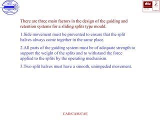
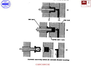
1. The document discusses different types of molds used in injection molding, including two plate molds, three plate molds, multi-daylight molds, stack molds, runnerless molds, insulated hot runner molds, and split molds.
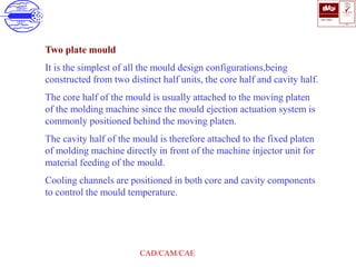
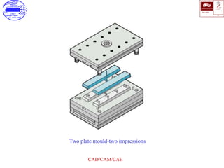
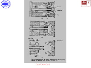
2. It provides details on the construction and functioning of each mold type, specifically how they are designed to handle components with features like undercuts, multiple cavities, and integrated runners and sprues.
3. The advantages and disadvantages of each mold configuration are outlined, such as their effectiveness for different production needs, material savings, and ease of manufacturing.
Injection molding is a manufacturing process that uses molds to produce plastic or rubber parts. Molds are hollow blocks that give the part its shape and allow it to cool. Thermoplastics can be molded repeatedly while thermosetting plastics set permanently after one molding. Injection molding machines consist of a hopper, barrel with a reciprocating screw, nozzle, and molds. The process involves melting plastic in the heated barrel and injecting it into the mold under pressure before allowing it to cool into the final shape.
This document describes the components and workings of a pneumatic sheet cutting machine. The key components are a pneumatic cylinder, 5/2 direction control foot valve, shearing blade, frame, and air circulating devices. The pneumatic cylinder uses compressed air to move the piston rod and shearing blade in two directions. The 5/2 direction control foot valve controls the direction of air flow to move the cylinder in forward and reverse. Compressed air is stored in an air receiver and distributed through piping to power the cylinder while minimizing pressure drops.
This document discusses different molding processes including structural foam molding, sandwich molding, and their advantages and disadvantages. Structural foam molding is a low pressure injection molding process where gas is introduced into molten polymer to reduce density and weight. It requires less pressure than other molding processes. Sandwich molding involves injecting two or more polymers one after another through the same gate to form a layered part with different materials for the core and skin. This allows for weight reduction and various material combinations. Advantages of these processes include lower costs, weight reduction, design flexibility, and strength to weight ratios. Disadvantages include potential for air bubbles or shrinkage.
This document provides details about a summer training project report on computer numerical control (CNC) machines completed by Amarkant Anchal at Bharat Heavy Electricals Limited in Jhansi, India under the guidance of Mr. Sateesh Soni. The report includes sections on CNC construction details, coordinate systems, positioning of the machine origin, motion control systems, part programming, and advantages of CNC machines. It also provides acknowledgements, a preface, index, and several chapters discussing topics like numerical control and applications of CNC.
The document discusses various methods for plastic welding, including mechanical joining using fasteners, adhesive bonding, and different types of welding. It describes several welding processes such as hot plate welding, hot gas welding, ultrasonic welding, friction welding, and laser welding. These welding methods use heat from external sources like hot plates or internal sources like ultrasonic vibrations to melt the plastic surfaces and join them together. Common applications of plastic welding include pipe assemblies, automotive parts, and food packaging.
(1) Compression molding is a manufacturing process used to mold thermosetting materials under heat and pressure in a mold cavity.
(2) The process involves preheating the molding material, placing it into the mold, applying pressure using a hydraulic press, and allowing the material to cure.
(3) Compression molding is commonly used to make electrical parts, dinnerware, gears, buttons, and automotive and medical components. It allows for high volume, low-cost production with minimal material waste.
Vacuum forming is a technique used to shape plastics by heating a plastic sheet and forming it over a mold using atmospheric pressure and vacuum. The process involves clamping a heated plastic sheet over a mold, turning on a vacuum to pull the sheet tightly over the mold, then removing the formed plastic piece once cooled. Vacuum forming is commonly used to make unusual shapes that would be difficult with other techniques.
This document discusses various plastic processing techniques. It begins by defining polymers and plastics, noting that polymers are composed of repeating monomer units and occur naturally or can be synthetic. Plastics are typically organic polymers that can be molded. The document then discusses two main types of plastics - thermoplastics, which can be remelted and reshaped, and thermosetting plastics, which permanently set their shape after heating. It proceeds to describe several plastic processing methods like injection molding, compression molding, and extrusion.
This document discusses different types of plastic welding. It describes five main types: hot gas plastic welding, laser welding, hot plate plastic welding, ultrasonic plastic welding, and friction welding. For each type, it provides details on the welding process and how heat is applied to fuse plastic materials. The document also covers the advantages of plastic welding, such as its speed, cleanliness, and ability to create permanent welds. Disadvantages include the permanence of welds and costs associated with some methods. Applications are in automotive and other industries where plastic welding provides a fast, lightweight joining method.
Transfer molding is a manufacturing process where a casting material is forced into an enclosed mold under pressure to form a casting. There are different types of transfer molding including resin transfer molding (RTM) and vacuum assisted resin transfer molding (VARTM). Thermoset polymers and fibers are common materials used. The transfer molding process involves placing the preheated molding compound in a transfer pot, closing the mold, and forcing the compound into the mold cavity under pressure where it cures. Applications include parts for the natural gas, electrical, and automotive industries. Advantages are uniform products and simpler production compared to other molding processes, while disadvantages include more material waste.
Rotational molding is a process used to create large, hollow plastic parts with uniform wall thickness. It is the only hollow parts process that can produce extremely large parts. The material is heated and rotated inside a mold to distribute it evenly. This allows for flexible designs by combining parts into one. Advantages include low-cost tooling, stress-free parts, and uniform thickness. However, cycles times are very long, ranging from 8-40 minutes. Also, only certain materials can be used and warping may occur without precise cooling. Competing processes like blow molding and injection molding have shorter cycles but cannot produce parts as large. Future developments include new materials, automation, and adding internal cooling.
Thermoforming is a process where a plastic sheet is heated and formed into a desired shape using pressure, vacuum, or mechanical methods. There are three main thermoforming methods: vacuum forming uses vacuum pressure to draw the heated sheet onto a mold; pressure forming uses compressed air to force the sheet onto the mold more quickly; and mechanical forming uses matching molds to shape the sheet without vacuum or pressure. Common materials thermoformed include plastics like ABS, polyethylene, and PVC. Applications include food packaging, automotive and aircraft parts.
Extrusion molding is a process that uses heat and pressure to form plastic into continuous lengths with uniform cross-sections like pipes, rods, or sheets. The plastic is fed into an extruder which heats and melts it before forcing it through a die. The shape of the die determines the shape of the extruded plastic. Common products made through extrusion molding include pipes, hoses, siding, fencing, deck railings, and plastic bags.
The document discusses injection molding techniques. It begins by defining injection molding as a process where molten plastic is injected into a mold to produce parts. It describes the basic components of older and modern injection molding machines. The process involves plastic pellets being melted and injected under pressure into molds through a nozzle to produce parts, which then cool and are ejected. Key advantages are high production rates and the ability to produce complex parts in various plastics.
Plasma arc machining uses ionized gas (plasma) to cut metals. It can cut materials that are difficult to cut with traditional techniques due to high thermal conductivity and oxidation resistance. The process involves generating a pilot arc to ignite the plasma and transferring the arc to the workpiece to melt and vaporize the metal, which is removed by the high-velocity gas. Plasma arc machining produces high-quality cuts at maximum productivity and is suitable for automated cutting applications.
This document discusses various manufacturing processes for plastic components. It begins by explaining what plastics are, how they are made from polymers, and the different types of plastics including thermoplastics and thermosets. It then covers several common plastic manufacturing processes like compression molding, transfer molding, injection molding, blow molding, and extrusion. For each process, it provides details on how the process works, suitable materials, advantages and disadvantages, and common applications. It also discusses defects that can occur in injection molding and additives that are often included with plastics.
Working elements of Pneumatic System with Circuits, Safety, InstallationMohammad Azam Khan
A pneumatic circuit is usually designed to implement the desired logics. However, there are several basics circuits, which can be integrated into the final circuit
The document discusses various polymer processing techniques. It begins by explaining that the main goal of polymer processing is to produce usable objects and lists the necessary parameters for processing including flow, heat transfer, mass transfer, and chemical reactions. It then focuses on extrusion, describing it as shaping material by forcing it through a die. Various extrusion techniques are discussed including single screw extrusion, twin screw extrusion, blown film extrusion, co-extrusion, and injection molding. Other processing methods summarized include thermoforming, vacuum forming, rotational molding, calendering, and spinning.
Plastics are synthetic or semi-synthetic organic polymers that can be molded into solid objects. There are two main types: thermoplastics, which can be reshaped when heated, and thermosetting plastics, which set permanently. Common plastic processing methods include injection molding, extrusion, blow molding, calendaring, thermoforming, rotational molding, and laminating. Injection molding uses heat and pressure to force melted plastic into a mold cavity. Extrusion produces solid or hollow shapes of constant cross-section. Blow molding inflates a hollow tube of plastic against a mold cavity. [/SUMMARY]
Injection Moulding Tool Design Manufacturing, Estimation and Comparison of L&...IOSR Journals
This document discusses the design, manufacturing, and analysis of an injection molding tool for an L&T power box side panel using different plastic materials. It first provides background on injection molding and describes the power box component. It then details the modeling of the part in Pro/E and analysis of the mold flow using plastic advisor to optimize filling. Mold calculations are presented to determine clamping force, shot capacity, cooling requirements, and machine specifications. The extraction of the core and cavity from the mold is illustrated along with the CNC manufacturing process. Cost comparisons of producing the part in different plastics are estimated.
Filament winding is a process that creates circular composite products with a hollow core by winding fiber material and resin around a mandrel or core. The fiber is wound in a precise pattern while under tension. The wound part is then cured either at room temperature or in an oven, after which the mandrel is removed, leaving a hollow composite structure. Filament winding is used to create products like storage tanks, pipes, aerospace and vehicle parts, and more.
it is PDF are typed of myself. study triks & short & sweet (Technical manual) Of Diploma in Plastics technology(DPT-DPMT). All machine knowlage in plastics processing.
Er. Naresh Dhaker
(8890881858)
(CIPET JAIPUR)
Vacuum forming is a thermoforming process that uses vacuum pressure to mold a plastic sheet over a mold. The process involves heating a plastic sheet until soft, draping it over a mold, applying vacuum pressure to suck the sheet onto the mold, then cooling and ejecting the molded part. Key aspects of vacuum forming include part and tool design, material selection, and processing techniques like heating, vacuum application, and cooling. Common applications are food containers, baths, vehicle interiors, and more.
Vacuum bag forming and pressure bag formingLahiru Dilshan
Vacuum bag forming and pressure bag forming are techniques used to consolidate composite materials. Vacuum bag forming uses vacuum pressure to pull resin-coated fibers into a mold cavity, while pressure bag forming uses both vacuum and positive air pressure to push the materials into the mold. These techniques are commonly used to produce parts for applications like medical devices, automotive, and recreation where higher fiber content and lower voids are needed compared to traditional layup methods. The processes involve laying up materials on a mold, sealing in a vacuum bag, and applying vacuum or pressure to consolidate the part before curing. They provide advantages like close tolerances and rapid prototyping for medium production quantities.
This document discusses plastic injection molding. It begins with an abstract that develops a steady state model to describe fluid behavior during the filling stage of injection molding. It then discusses factors that affect part quality and different approaches that have been used to determine optimal process parameters, including mathematical models, Taguchi methods, neural networks, and more. The rest of the document provides details on an experiment conducted to analyze how independent variables like temperature, pressure, and flow rate affect the dependent variable of part weight. It summarizes the injection molding process and concludes that pressure and flow rate had the biggest impact on part weight.
This document provides an overview of thermoforming and other plastic processing techniques. It discusses the history and development of thermoforming from World War II to today. It then describes different types of thermoforming like vacuum, pressure, and mechanical thermoforming. The document also discusses extrusion, injection molding, and blow molding processes. It provides details on the history, process, materials used, advantages and disadvantages, and applications of each technique. Finally, it mentions some Pakistani industries that utilize these plastic processing methods.
The document discusses the feed system components used in injection moulding including the sprue, runner, and gate. It describes the sprue as the tapered passage connecting the nozzle to the mould and the sprue bush. It explains that the runner is the channel connecting the sprue to the gate entrance of the cavity. Finally, it notes that the gate is the small channel connecting the runner to the cavity and discusses different gate types and how to design and balance the feed system.
Forging considerations -requirements and rules-redesign of components for forging and case studies.
Design of components for powder metallurgy- requirements and rules-case studies.
Design of components for injection moulding- requirements and rules-case studies.
Cimatron là sản phẩm cùng tên với công ty mẹ là Cimatron Group. Nó giúp lập trình và cung cấp phần mềm CAD/CAM cho các ứng dụng sản xuất, chế tạo công cụ và lập trình CNC.
Gating system is one of five major systems in the design of plastic molds. Its design will affect product ranking, number of mold cavities, form of mold structure, choice of injection moulding machine size, level of injection molding costs, level of mold manufacturing costs, difficulty of mold manufacturing, pressure, post-processing methods and costs during manufacturing. Slight effects will cause product to appear burrs, shrinkage, deformation, air lines, pinching, trapped air, easy to crack, difficult to cut, difficult to repair, difficult to take, difficult to take, etc .; serious effects will make product unable to produce, unfilling injection, obvious and severe clamping, product burnt, damage to appearance, bending of mold core, dragging product to scrap, unable to perform post-processing, unable to package, unable to distinguish left and right, etc.
The document outlines 15 steps for mold design and focuses on design considerations. It discusses analyzing product drawings, determining the injection machine type and number of cavities, selecting the parting surface, designing the gating system, ejection system, cooling system, and other elements. Key points include choosing an appropriate parting surface, layout of the flow channel and gate, ejection device, water distribution, exhaust, draft angles, and simplifying the mold structure as much as possible.
A presentation on topic Plastics ceramics and glass processing, the all content based on GTU syllabus And ideal for gtu students. The PPT contains videos for clear understanding of concept.
The document discusses the production process of an engine block or monoblock. It describes the monoblock as the main body of the engine that houses the cylinders. It contains internally the cylinders, pistons, crankshaft, gears, valves, rods and lubrication network. Externally it supports other engine components. The monoblock must withstand high temperatures and pressures from combustion, and prevent leaks while efficiently conducting heat. Production involves casting aluminum or iron alloys using sand molds in a pressure die casting process.
This document provides an overview of plastic mould design and the injection moulding process. It discusses the importance of plastic parts in modern industries and advantages of plastics over metals. Key topics covered include design considerations for plastic parts, common plastic materials, types of moulds, injection mould components like the cavity and core, and the six main steps of the injection moulding process: mould closing and clamping, injection, dwelling, cooling, plasticizing resin, and mould opening and ejection. The document also provides a brief overview of injection moulding machines.
The document discusses the process of injection moulding. It begins with an introduction to injection moulding, describing how it is used to produce plastic components. It then provides historical background on the development of injection moulding from the late 19th century onwards. The document outlines some of the key advantages of injection moulding, such as high production rates and dimensional accuracy of parts. It also notes some limitations, like high initial costs for moulds and machinery. Finally, it includes a glossary defining technical terms used in injection moulding.
Proceso de fabricación del monoblock de un motorIvan Heli
The document provides details about the production process of an engine block or monoblock. It describes the monoblock as the main body of the engine that houses the cylinders. It contains internally the cylinders, pistons, crankshaft, gears, and lubrication system. Externally it supports other engine components. The monoblock must withstand high temperatures and pressures from combustion. It is typically made of cast iron or aluminum alloy.
Technology for Plastic Mold Tooling - Direct Metal Deposition HCL Technologies
This whitepaper highlights the benefits of DMD(Direct Metal Deposition) technology in mold cycle time reduction. It presents a comparative analysis conducted for cycle time performance of a mold consisting of a conventionally machined tool steel insert to a mold fitted with a Chromium Copper insert with a coating of tool steel deposited by the DMD process.
Polymer Processing( Manufacturing Of Polymer)Haseeb Ahmad
This document discusses various polymer processing techniques including extrusion, injection molding, blow molding, and compression molding. It provides definitions and descriptions of each process, diagrams to illustrate the basic steps, and discusses important terms and considerations for each technique. The key components and functioning of extruders and injection molding machines are explained. Examples of common applications for each type of processing are also provided.
The document discusses Pacific Wedgeplug valves, including:
1) Key features of Wedgeplug valves like simple construction, metal sealing surfaces, and bi-directional sealing capability.
2) Typical applications in refineries and petrochemical plants, including isolation valves in various units.
3) Design details like the plug, body, seats, bonnet, and Wedgetorque operator. Purging and flushing processes are described to enhance performance.
Blow Molding Process on Manufacturing Technology .
Tackles about the definition of Blow molding process, its various types , advantages and disadvantages and the application of it on a manufacturing set-up.
This document discusses various methods for producing composites, which are divided into open molding and closed molding. Open molding methods described include hand lay-up, spray-up, and filament winding. Closed molding methods include compression molding, pultrusion, vacuum bag molding, and vacuum infusion processing. Each method is briefly described in terms of its process, molds used, advantages, and typical products produced.
Justin Sly presented on his 1st co-op rotation working in product engineering at Aerials. He summarized four projects: [1] updating weldment assembly drawings for improved clarity; [2] redesigning an outrigger rod cover to prevent interference and scraping; [3] implementing new logo placements on aerial vehicles per a client request; and [4] redesigning a platform cover and cup holder to better allow for debris cleanout. The presentation highlighted lessons learned about engineering design, manufacturing processes, and software tools like SolidWorks and DraftSight.
OPTIMIZED DIE STRUCTURE DESIGN OF PLASTIC INJECTION MOULD USING FEM TECHNIQUEIjripublishers Ijri
The Aim of this thesis work is to reduce weight and cost of the injection mold by removing unwanted materials and using
low cost materials at non-stress region areas.
A general large size model will be prepared to design the mold structure using theoretical method.
Complete level of mold parts and assembly will be prepared to conduct analysis.
Structural analysis will be conducted on mould to find stress locations and non-effective locations.
Modifications will be done on mold according to obtained results.
OPTIMIZED DIE STRUCTURE DESIGN OF PLASTIC INJECTION MOULD USING FEM TECHNIQUEIjripublishers Ijri
A die is a specialized tool used in manufacturing industries to cut or shape material mostly using a press. Like molds,
dies are generally customized to the item they are used to create. Products made with dies range from simple paper clips
to complex pieces used in advanced technology.
The Aim of this thesis work is to reduce weight and cost of the injection mold by removing unwanted materials and using
low cost materials at non-stress region areas.
A general large size model will be prepared to design the mold structure using theoretical method.
Complete level of mold parts and assembly will be prepared to conduct analysis.
Structural analysis will be conducted on mould to find stress locations and non-effective locations.
Modifications will be done on mold according to obtained results.
The document summarizes several common polymer forming and shaping processes:
1. Extrusion is the largest production method where raw materials are melted and forced through a die to make shapes. Screw extruders are commonly used.
2. Injection molding forces melted polymer into a mold cavity using a hydraulic plunger or screw. It can make complex parts at high volumes.
3. Blow molding uses extruded tubes or injection molded parisons that are expanded using air pressure inside closed molds to form hollow shapes like bottles.
4. Other processes discussed include rotational molding, thermoforming, and compression molding which use heat and pressure to form polymer parts in molds.
Increase in production with automation in injection molding machineMohammed Asker Ali
This chapter provides an overview of injection molding and the history of its development. It discusses how injection molding machines work and the key components involved, including the injection system, mold system, clamping system, and control system. Important parameters that influence the quality of molded parts are also covered, such as temperature, injection pressure, and cooling time.
The document provides a table listing various commands and shortcuts for SolidWorks. It includes categories for File, Edit, View, Insert, Tools, Window, Help and Others. For each category it lists the relevant commands and associated keyboard shortcuts. The table contains over 60 commands and shortcuts for navigating, creating, editing and viewing models in SolidWorks.
This presentation introduces a new Engineering Change Request (ECR) process alongside the existing Process Change Request (PCR) process for HYG suppliers to manage design and process changes. The ECR process is similar to the PCR but directs engineering changes to HYG's engineering team for review, while the PCR is for process changes. Suppliers submit change requests through a common front page on the HYG change request site to select the appropriate process. The presentation provides overviews and requirements for submitting ECR and PCR requests through the online system, including required fields and the review and approval process handled by HYG.
Change management involves planning, organizing, coordinating, and controlling changes to ensure they are implemented smoothly with minimal disruption. It is the responsibility of top management to oversee changes that affect suppliers, customers, and competitors. An effective change management process includes pre-implementation planning, implementation, and post-implementation review. It also requires testing changes and obtaining user acceptance before full production rollout. Regular audits help ensure compliance with change control procedures and guidelines.
This document discusses change management in engineering and construction projects. It defines change as any deviation from the agreed upon project scope, schedule, or cost. The importance of change management is discussed, as modern projects face challenges like reduced timelines that require changes. An effective change management process addresses changes to scope, schedule, cost and their interdependencies. The document outlines responsibilities for managing change, including for the project manager, project engineering manager, change coordinator and other roles. It describes methods for controlling changes through document review, tracking design growth, and change review meetings. The conclusion emphasizes meeting project objectives, addressing stakeholder interests, and maintaining trust and a documented process.
Change management involves planning, organizing, coordinating, and controlling changes to ensure they are implemented as approved with minimal disruption. It is the responsibility of top management to manage not only employees but also suppliers, customers, and competitors affected by changes. The steps for change management include pre-implementation, implementation, and post-implementation phases. An audit of change controls evaluates the identification, testing, approval, and documentation of all changes to ensure standards and procedures are followed.
Change management involves planning, organizing, coordinating, and controlling changes to ensure they are implemented smoothly with minimal disruption. It is the responsibility of top management to oversee changes that affect suppliers, customers, and competitors. An effective change management process includes pre-implementation planning, implementation, and post-implementation review. It also requires testing changes and obtaining user acceptance before full production rollout. Regular audits help ensure compliance with change control procedures and guidelines.
Sheet metal working involves cutting and forming thin metal sheets. The main processes are cutting, bending, and drawing. Cutting separates sheets into parts using dies and presses. Proper die clearance is important for good cuts. Forces to cut metal depend on material thickness, diameter/length of cut, and material strength. Progressive and compound dies can perform multiple operations in one or a few presses. The center of pressure allows even force distribution for irregular cuts to avoid bending. Tapered or stepped punches can reduce high cutting forces. Efficient strip layout minimizes scrap.
This slide is special for master students (MIBS & MIFB) in UUM. Also useful for readers who are interested in the topic of contemporary Islamic banking.
A review of the growth of the Israel Genealogy Research Association Database Collection for the last 12 months. Our collection is now passed the 3 million mark and still growing. See which archives have contributed the most. See the different types of records we have, and which years have had records added. You can also see what we have for the future.
বাংলাদেশের অর্থনৈতিক সমীক্ষা ২০২৪ [Bangladesh Economic Review 2024 Bangla.pdf] কম্পিউটার , ট্যাব ও স্মার্ট ফোন ভার্সন সহ সম্পূর্ণ বাংলা ই-বুক বা pdf বই " সুচিপত্র ...বুকমার্ক মেনু 🔖 ও হাইপার লিংক মেনু 📝👆 যুক্ত ..
আমাদের সবার জন্য খুব খুব গুরুত্বপূর্ণ একটি বই ..বিসিএস, ব্যাংক, ইউনিভার্সিটি ভর্তি ও যে কোন প্রতিযোগিতা মূলক পরীক্ষার জন্য এর খুব ইম্পরট্যান্ট একটি বিষয় ...তাছাড়া বাংলাদেশের সাম্প্রতিক যে কোন ডাটা বা তথ্য এই বইতে পাবেন ...
তাই একজন নাগরিক হিসাবে এই তথ্য গুলো আপনার জানা প্রয়োজন ...।
বিসিএস ও ব্যাংক এর লিখিত পরীক্ষা ...+এছাড়া মাধ্যমিক ও উচ্চমাধ্যমিকের স্টুডেন্টদের জন্য অনেক কাজে আসবে ...
A workshop hosted by the South African Journal of Science aimed at postgraduate students and early career researchers with little or no experience in writing and publishing journal articles.
Chapter wise All Notes of First year Basic Civil Engineering.pptxDenish Jangid
Chapter wise All Notes of First year Basic Civil Engineering
Syllabus
Chapter-1
Introduction to objective, scope and outcome the subject
Chapter 2
Introduction: Scope and Specialization of Civil Engineering, Role of civil Engineer in Society, Impact of infrastructural development on economy of country.
Chapter 3
Surveying: Object Principles & Types of Surveying; Site Plans, Plans & Maps; Scales & Unit of different Measurements.
Linear Measurements: Instruments used. Linear Measurement by Tape, Ranging out Survey Lines and overcoming Obstructions; Measurements on sloping ground; Tape corrections, conventional symbols. Angular Measurements: Instruments used; Introduction to Compass Surveying, Bearings and Longitude & Latitude of a Line, Introduction to total station.
Levelling: Instrument used Object of levelling, Methods of levelling in brief, and Contour maps.
Chapter 4
Buildings: Selection of site for Buildings, Layout of Building Plan, Types of buildings, Plinth area, carpet area, floor space index, Introduction to building byelaws, concept of sun light & ventilation. Components of Buildings & their functions, Basic concept of R.C.C., Introduction to types of foundation
Chapter 5
Transportation: Introduction to Transportation Engineering; Traffic and Road Safety: Types and Characteristics of Various Modes of Transportation; Various Road Traffic Signs, Causes of Accidents and Road Safety Measures.
Chapter 6
Environmental Engineering: Environmental Pollution, Environmental Acts and Regulations, Functional Concepts of Ecology, Basics of Species, Biodiversity, Ecosystem, Hydrological Cycle; Chemical Cycles: Carbon, Nitrogen & Phosphorus; Energy Flow in Ecosystems.
Water Pollution: Water Quality standards, Introduction to Treatment & Disposal of Waste Water. Reuse and Saving of Water, Rain Water Harvesting. Solid Waste Management: Classification of Solid Waste, Collection, Transportation and Disposal of Solid. Recycling of Solid Waste: Energy Recovery, Sanitary Landfill, On-Site Sanitation. Air & Noise Pollution: Primary and Secondary air pollutants, Harmful effects of Air Pollution, Control of Air Pollution. . Noise Pollution Harmful Effects of noise pollution, control of noise pollution, Global warming & Climate Change, Ozone depletion, Greenhouse effect
Text Books:
1. Palancharmy, Basic Civil Engineering, McGraw Hill publishers.
2. Satheesh Gopi, Basic Civil Engineering, Pearson Publishers.
3. Ketki Rangwala Dalal, Essentials of Civil Engineering, Charotar Publishing House.
4. BCP, Surveying volume 1
This presentation was provided by Steph Pollock of The American Psychological Association’s Journals Program, and Damita Snow, of The American Society of Civil Engineers (ASCE), for the initial session of NISO's 2024 Training Series "DEIA in the Scholarly Landscape." Session One: 'Setting Expectations: a DEIA Primer,' was held June 6, 2024.
Leveraging Generative AI to Drive Nonprofit InnovationTechSoup
In this webinar, participants learned how to utilize Generative AI to streamline operations and elevate member engagement. Amazon Web Service experts provided a customer specific use cases and dived into low/no-code tools that are quick and easy to deploy through Amazon Web Service (AWS.)
Leveraging Generative AI to Drive Nonprofit Innovation
types_of_moulds-split_mould.ppt
1. ISO 9001
B U K A S
QUALITY
MANAGEMENT
Qi
006
V
CAD/CAM/CAE
Types of Moulds
2. ISO 9001
B U K A S
QUALITY
MANAGEMENT
Qi
006
V
CAD/CAM/CAE
Injection Moulds
The molds consist of two main parts: the cavity and core. The core
forms the main internal surfaces of the part. The cavity forms the
major external surfaces of the part. Typically, the core and cavity
separate as the mold opens, so that the part can be removed. This mold
separation occurs along the interface known as the parting line.
An injection mold is usually made in two halves or sections and held
together in the closed position by the molding press. The mold is
generally made out of tool steel and is provided with channels for
cooling, heating and venting, Ejector pins and other devices may be
incorporated.
3. ISO 9001
B U K A S
QUALITY
MANAGEMENT
Qi
006
V
CAD/CAM/CAE
Types of Moulds
1.Two Plate Mould
2.Three Plate Mould
3.Multi-daylight mould
4.Stack Mould
5.Runnerless Mould
6.Insulated Hot Runner Mould
7.Split Mould
4. ISO 9001
B U K A S
QUALITY
MANAGEMENT
Qi
006
V
CAD/CAM/CAE
Two plate mould
It is the simplest of all the mould design configurations,being
constructed from two distinct half units, the core half and cavity half.
The core half of the mould is usually attached to the moving platen
of the molding machine since the mould ejection actuation system is
commonly positioned behind the moving platen.
The cavity half of the mould is therefore attached to the fixed platen
of molding machine directly in front of the machine injector unit for
material feeding of the mould.
Cooling channels are positioned in both core and cavity components
to control the mould temperature.
5. ISO 9001
B U K A S
QUALITY
MANAGEMENT
Qi
006
V
CAD/CAM/CAE
Two plate mould-two impressions
6. ISO 9001
B U K A S
QUALITY
MANAGEMENT
Qi
006
V
CAD/CAM/CAE
Advantage
1.Simplicity of design
2.Utilization of standard mould parts
3.The cheapest design
Disadvantage
1.Limitations in component gate positioning when conventionally
feeding
2.Lack of available space for balanced feeding of multiple cavities
3.High material waste level(Sprues and runners).
7. ISO 9001
B U K A S
QUALITY
MANAGEMENT
Qi
006
V
CAD/CAM/CAE
Three plate mould
The three-plate mould differs from the more common two-plate design
format in terms of utilizing more than one split or parting line.
The tool construction is divided into three distinct plate build-ups which
separate from each other on opening.
One opening provides clearance for component ejection, while the other
allows for sprue ejection and clearance.
8. ISO 9001
B U K A S
QUALITY
MANAGEMENT
Qi
006
V
CAD/CAM/CAE
Three plate mould
This type of mold is made up of three plates:
(1) the stationary or runner plate is attached to the stationary platen,
and usually contains the sprue and half of the runner,
(2) the middle plate or cavity plate, which contains half of the runner
and the gate, is allowed to float when the mold is open; and
(3) the movable plate or force plate contains the molded part and
ejector system for the removal of the molded part.
A linkage system between the three major mold plates controls the
mold-opening sequence. The mold first opens at the primary
parting line breaking the pinpoint gates and separating the parts
from the cavity side of the mold. When the press starts to open, the
middle plate and the movable plate move together, thus releasing
the sprue and runner system and degating the molded part. This
type of mold design makes it possible to segregate the runner
system and the part when the mold opens. The die design makes it
possible to use center-pin-point gating.
9. ISO 9001
B U K A S
QUALITY
MANAGEMENT
Qi
006
V
CAD/CAM/CAE
Schematic of a two-cavity, three-plate mold
with cutaway view -first stage of opening
phase
Second phase of opening
Final opening phase
10. ISO 9001
B U K A S
QUALITY
MANAGEMENT
Qi
006
V
CAD/CAM/CAE
Multi-daylight mould
The basic mould consist of two half, when these two half's are opened the
moldings can be extracted.The space between the mould plates is termed
as Daylight.
A mould in which more than one daylight occurs when it is opened.This
term refers to underfeed mould.
In stripper plate mould, it consists of three plates namely, fixed mould
plate, a moving mould plate and a stripper plate.When the mould is fully
opened there are two daylights.The molding and feed system are removed
from the first daylight, that is from between the striper plate and the fixed
mould plate.
11. ISO 9001
B U K A S
QUALITY
MANAGEMENT
Qi
006
V
CAD/CAM/CAE
Stack Mould
A Multilevel injection mold in which two sets of cavities are filled
simultaneously.
The stack mold, reduces the clamp force required by multi-cavity molds.
Typically, multiple cavities are oriented on a single parting line and the
required clamp force is the sum of the clamp needed by each cavity plus
the runner system.
In stack molds, cavities lie on two or more stacked parting lines. The
injection forces exerted on the plate separating parting lines cancel, so the
resulting clamp force is the same as for just one parting line.
Stack molds produce more parts per cycle than would otherwise be
possible in a given size molding press. The stacked injection mold is just
what the name implies. A multiple two-plate mold is placed one on top of
the other. This construction can also be used with three-plate molds and
hot-runner molds.
A stacked two-mold construction doubles the output from a single press
and reduces the clamping pressure required to one half, as compared to a
mold of the same number of cavities in a two-plate mold. This method is
sometimes called "two-level molding“.
12. ISO 9001
B U K A S
QUALITY
MANAGEMENT
Qi
006
V
CAD/CAM/CAE
Runnerless mould
In this process of injection molding, the runners are kept hot in order
to keep the molten plastic in a fluid state at all times. In effect this is a
"runnerless" molding process and is sometimes called the same. In
runnerless molds, the runner is contained in a plate of its own.
Hot runner molds are similar to three-plate injection molds, except
that the runner section of the mold is not opened during the molding
cycle.
The heated runner plate is insulated from the rest of the cooled mold.
Other than the heated plate for the runner, the remainder of the mold is
a standard two-plate die
13. ISO 9001
B U K A S
QUALITY
MANAGEMENT
Qi
006
V
CAD/CAM/CAE
14. ISO 9001
B U K A S
QUALITY
MANAGEMENT
Qi
006
V
CAD/CAM/CAE
Advantage
1.Reduced cycle time as a result of having a component cooling
requirement only.The runner and feed system remain molten above the
quickly frozen gate.
2.Material savings results from having no sprue or runner systems to
granulate.
3.Labor and post molding finishing costs are significantly reduced without
the need for degating of the moldings.
4.The ability to gain greater control over the mould filling and flow
characteristics of the molten polymer during the filling phase of the
molding cycle.
15. ISO 9001
B U K A S
QUALITY
MANAGEMENT
Qi
006
V
CAD/CAM/CAE
Insulated hot runner mould
The insulated hot runner mould is the simplest of all the hot-runner
designs.
In this type of molding, the outer surface of the material in the
runner acts like an insulator for the molten material to pass through.
In the insulated mold, the molding material remains molten by
retaining its own heat. Sometimes a torpedo and a hot probe are
added for more flexibility. This type of mold is ideal for multicavity
center-gated parts.
16. ISO 9001
B U K A S
QUALITY
MANAGEMENT
Qi
006
V
CAD/CAM/CAE
17. ISO 9001
B U K A S
QUALITY
MANAGEMENT
Qi
006
V
CAD/CAM/CAE
Advantages
1.The feed system can easily be stripped and cleaned,resulting in very
little material or color contamination occurring.
2.Mould start-up times are faster when compared to other hot runner
mould systems.
3.Moulds are very much cheaper to manufacture than the other hot
runner mould designs
4.Thermally unstable polymers may be processed using such a system.
18. ISO 9001
B U K A S
QUALITY
MANAGEMENT
Qi
006
V
CAD/CAM/CAE
Split Moulds
A mould in which the cavity is formed by two or more parts held
together by a chase bolster during the injection phase.
A two or more steel blocks containing the impression which can be
opened, normally at right angles to the mould’s axis, to facilitate the
molding of external undercut type comments.
In Split mould, i )guiding the splits in the desired direction ii)
Actuating the splits and iii ) securely locking the splits in position
prior to the material being injected into the mold.
19. ISO 9001
B U K A S
QUALITY
MANAGEMENT
Qi
006
V
CAD/CAM/CAE
There are three main factors in the design of the guiding and
retention systems for a sliding splits type mould.
1.Side movement must be prevented to ensure that the split
halves always come together in the same place.
2.All parts of the guiding system must be of adequate strength to
support the weight of the splits and to withstand the force
applied to the splits by the operating mechanism.
3.Two split halves must have a smooth, unimpeded movement.
20. ISO 9001
B U K A S
QUALITY
MANAGEMENT
Qi
006
V
CAD/CAM/CAE
21. ISO 9001
B U K A S
QUALITY
MANAGEMENT
Qi
006
V
CAD/CAM/CAE
Undercut Moulds
A molding which has a recess or projection is termed an Undercut
molding.
External Undercut
Any recess or projection on the outside surface of the component
which prevents its removal from the cavity is termed an external
undercut.
22. ISO 9001
B U K A S
QUALITY
MANAGEMENT
Qi
006
V
CAD/CAM/CAE
23. ISO 9001
B U K A S
QUALITY
MANAGEMENT
Qi
006
V
CAD/CAM/CAE
There are two forms of undercut to be considered:
a) The undercut may be local, in that the recess or projection occurs in
one position only.For example-clip on a pen cap.
b) The undercut may be continuous recess or a projection on the
periphery of the components.For example-water connector has a
number of undercuts.
In the above case, it is necessary to split the cavity insert into parts and
open these, generally at right angles to the line of draw, to relieve
the undercut before the moulding is removed.
Since the cavity is in two pieces, a joint line will be visible on the
finished product.The joint line, on an undercut component, is
comparable to the parting line on an in line of draw component and
the same careful consideration must be exercised in deciding its
position before attempting to design the mould.
24. ISO 9001
B U K A S
QUALITY
MANAGEMENT
Qi
006
V
CAD/CAM/CAE
Internal undercut
An internal undercut is any restriction which prevents molding from
being extracted from the core in line of draw.
The specific design adopted depends upon the shape and position of
the restriction.
A component which has a local undercut portion can be successfully
molded in the conventional mould by incorporating the undercut form
on a form pin.
A circular hardened steel pin which incorporates molding form and is
used for the molding of internal undercuts.It may have either a straight
or an angled action is termed as form pin.
25. ISO 9001
B U K A S
QUALITY
MANAGEMENT
Qi
006
V
CAD/CAM/CAE
26. ISO 9001
B U K A S
QUALITY
MANAGEMENT
Qi
006
V
CAD/CAM/CAE
Finger Cam
A hardened steel rod, fitted at an angle to the mold plate for the purpose of
operating splits and side cores.
The splits mounted in guides on the moving mould plate, have
corresponding angled circular holes to accommodate these finger cams.
27. ISO 9001
B U K A S
QUALITY
MANAGEMENT
Qi
006
V
CAD/CAM/CAE
28. ISO 9001
B U K A S
QUALITY
MANAGEMENT
Qi
006
V
CAD/CAM/CAE
29. ISO 9001
B U K A S
QUALITY
MANAGEMENT
Qi
006
V
CAD/CAM/CAE
The distance traversed by each split across the face of the mould plate is
determined by the length and angle of the finger cam.The movement can
be computer by the formula
M=(L sinø) – (c/cosø)
As the required movement is known from the amount of component
undercut, the following rearranged formula to determine the finger cam
length is of greater use, apart from checking purposes
L=(M/sinø) + (2c/sin2ø)
Where,
M= splits movement
Ø = angle of finger cam
L=working length of finger cam
c =clearance
30. ISO 9001
B U K A S
QUALITY
MANAGEMENT
Qi
006
V
CAD/CAM/CAE
Dog-leg cam actuation
Here, method of actuation is used where a greater splits delay is required
than can be achieved by the finger cam method.
The dog-leg cam which is of a general rectangular section, is mounted in
the fixed mould plate.Each split incorporates a rectangular hole, the
operating face of which has a corresponding angle to that of the cam.
31. ISO 9001
B U K A S
QUALITY
MANAGEMENT
Qi
006
V
CAD/CAM/CAE
32. ISO 9001
B U K A S
QUALITY
MANAGEMENT
Qi
006
V
CAD/CAM/CAE
33. ISO 9001
B U K A S
QUALITY
MANAGEMENT
Qi
006
V
CAD/CAM/CAE
Cam track actuation
A hardened steel member fitted to one mould plate for the purpose of
operating splits and side cores.
This method of actuation utilizes a cam track machined into a steel plate
attached to the fixed mould half.A boss fitted to both sides of the split, runs in
this track.The movement of the splits can thus be accurately controlled by
specific cam track design.
To ensure smooth operation a generous radius should be incorporated at each
point where the cam track form changes.A radius or taper should also be
included at the entrance to form a lead-in for the boss as it re-enters the track.
34. ISO 9001
B U K A S
QUALITY
MANAGEMENT
Qi
006
V
CAD/CAM/CAE
35. ISO 9001
B U K A S
QUALITY
MANAGEMENT
Qi
006
V
CAD/CAM/CAE
36. ISO 9001
B U K A S
QUALITY
MANAGEMENT
Qi
006
V
CAD/CAM/CAE
Spring actuation
In this design, which obviates the use of cams altogether, incorporates
compression springs to force the splits apart and utilizes the angled faces
of the chase bolster to close them.The outward splits movement must
therefore be limited so that they will re-enter the chase bolster as the
mould is closed.
The splits are mounted on the mold plate and retained by guide strips.
Studs project from the base of the splits into a slot machined in the mould
plate.
A compression spring is fitted between the studs in a link-shaped pocket
situated in the lower mould plate.
37. ISO 9001
B U K A S
QUALITY
MANAGEMENT
Qi
006
V
CAD/CAM/CAE
38. ISO 9001
B U K A S
QUALITY
MANAGEMENT
Qi
006
V
CAD/CAM/CAE
Hydraulic actuation
In this design the splits are actuated hydraulically and it is not
dependent on the opening movement of the mould.
The splits can be operated automatically at any specific time by
including this function in the operating programme of the machine.
On machines which do not programme for auxiliary cylinder control it
is necessary to add a separate hydraulic operating circuit to the existing
system.
39. ISO 9001
B U K A S
QUALITY
MANAGEMENT
Qi
006
V
CAD/CAM/CAE
40. ISO 9001
B U K A S
QUALITY
MANAGEMENT
Qi
006
V
CAD/CAM/CAE
Split core
A steel core manufactured in two or more parts to facilitate the molding
of internal undercut components.
The split core design is used for components which have extensive
internal undercuts that cannot be incorporated on a form pin.
The split core may be moved forward either in a straight plane or an
angled plane.
41. ISO 9001
B U K A S
QUALITY
MANAGEMENT
Qi
006
V
CAD/CAM/CAE
Mould for Internally Threaded components
The internal thread comes within the broad definition of an
internal undercut in that the thread forms a restriction which
prevents the straight draw removal of the molding from the
core.
i) Split core design
ii) Collapsible core design
iii) Unscrewing mold design
42. ISO 9001
B U K A S
QUALITY
MANAGEMENT
Qi
006
V
CAD/CAM/CAE
43. ISO 9001
B U K A S
QUALITY
MANAGEMENT
Qi
006
V
CAD/CAM/CAE
Moulds for Externally threaded components
An external thread comes within the broad definition of an external
undercut, namely a restriction situated in the outside form of a
molding which prevents straight draw removal of the molding from
the cavity.
In undercut component, the threaded type of molding can be
unscrewed from the cavity and in certain cases this allows a
simplified design.
But in automatic operation is required some form of rotary motion
within the mold is necessary to perform the unscrewing operation
automatically.
Another method often used is stripping design, allowing for fast
production cycles, is limited to those components which incorporate
roll threads.
44. ISO 9001
B U K A S
QUALITY
MANAGEMENT
Qi
006
V
CAD/CAM/CAE
45. ISO 9001
B U K A S
QUALITY
MANAGEMENT
Qi
006
V
CAD/CAM/CAE
Standard Mold bases
The importance of standardizing a mould base is to manufacture on a
rigidly controlled basis,all possible parts of the mould which permits
considerable pre-fabrication and eliminating a lot of work done by highly
skilled man power in the mould and die making shop.
It takes many hours to produce mould components by tool room methods
for which some times large and most expensive machines are required.
When components are standardized and put in the market in a ready to
assemble condition, the only major work on any mould to be done will be
core and cavity for which more skilled man hours would be made
available.This in turn will increase the rate of production, faster
delivering of the moulds thereby increasing the profitability of the mould
and die making industry.
46. ISO 9001
B U K A S
QUALITY
MANAGEMENT
Qi
006
V
CAD/CAM/CAE
Advantage
The advantage of standard mould base can be broadly grouped into
three areas, for designers, manufacturers and customers.
Designers
•Risk due to drawing errors are minimized
•By adopting standardization, the draughtsman does only the
essential portion of the job i.e core and cavity profiles, ejection
location, gate & cooling details only.
•A wide variety of mould drawings could be drawn in minimum
time without fatigue or repetitive drafting.
•Mould parts could be easily numbered so that the batch production
in manufacturing will be easy.
47. ISO 9001
B U K A S
QUALITY
MANAGEMENT
Qi
006
V
CAD/CAM/CAE
Manufacturer
*The time spent on the manufacturing mould base can be utilized for
manufacturing core and cavity details so that the efficiency of the output
can be easily increased with the availability of manpower.
•Machinist replace highly skilled mould makers
•Duplication will be easy if required and consumes less time.
•Better control on cost can be achieved on batch production techniques.
•Interchangeability of parts will be easy.
•Tool maintenance is reduced.
Customers
•The delivery time can be easily reduced
•The quality of the product can be assured
•Total cost of the tool will be reduced.
48. ISO 9001
B U K A S
QUALITY
MANAGEMENT
Qi
006
V
CAD/CAM/CAE
Calculation of strength of cavities
a)Rectangular cavity
The maximum deflection commonly allowed is 0.13-0.25mm depending upon
the size of the tool.Of this 0.1-0.2mm may be due to clearances between the
blocks of the built-up mould and elongation of the bolster or register faces.For
stress design purposes, therefore, a maximum deflection of 0.025-0.05mm is
usually take.The approximate thickness of the side wall required may be
calculated from the following formula:
t = 3( c.p.d4 / E.γ )
γ - Maximum deflection of side walls(cm)
c- Constant , t – thickness of cavity wall (cm)
p- Maximum cavity pressure(say 630 Kg/cm2)
d- Total depth of cavity wall(cm)
E- Modulus of elasticity for steel(0.1 x10⁶ kgf/cm2)
49. ISO 9001
B U K A S
QUALITY
MANAGEMENT
Qi
006
V
CAD/CAM/CAE
b) Cylindrical cavities:
Increase in radius due to the internal pressure of injected material can
be determined from
γ = (rp / E) [{r2+R2)/(R2-r2) +m)]
γ – Increase of inside radius(cm)
r- Original inside radius(cm)
R- Original outside radius(cm)
m- Poisson’s ratio(0.25 for steel)
p- Cavity pressure, say630kg/cm2
50. ISO 9001
B U K A S
QUALITY
MANAGEMENT
Qi
006
V
CAD/CAM/CAE
Calculation of Strength of Guide pillar
The size of the working diameter of guide pillar to use depends on the
size of the mould and whether or not a size force is likely to be exerted
on it. The moulds with deep and heavy cross-sectional cores exert side
thrusts, and the guide pillars should be strong enough to absorb them
without any damages.
Side thrust(Q) can be calculated from the equation,
Q = 2/3d.h.pf(K.g) for circular cores
d= Maximum diameter of core(cm)
h= Height of core(cm)
pf= Cavity pressure causing side thrust taking into consideration the
effect of clamping force(kg/cm2) say 300kg/cm2
51. ISO 9001
B U K A S
QUALITY
MANAGEMENT
Qi
006
V
CAD/CAM/CAE
Q= a.h.pf
a= Maximum side of core(cm)
h= Height of core(cm)
pf= say 300 kg/cm2
Working diameter(d) of guide pillar
d(4Q/N fs )½
Q= Side thrust (kg)
N= Number of pillars
fs= shear stress, say 16 Tons/sq.inch=158 x 16 kg/cm2
52. ISO 9001
B U K A S
QUALITY
MANAGEMENT
Qi
006
V
CAD/CAM/CAE
Determination of Support Pillar requirements:
W= 8ZS/M; Z= LB2/6; A=W/P
W=permissible load on support plate(kg)
S=permissible working stress(kg/cm2)[840kg/cm2]
M=Distance between supports(cm)
L=Length of support plate(cm)
Z=Section modulus(cm3)
B= Thickness of support plate(cm)
P=Maximum unit pressure on support plate(kg/cm2)[630 kg/cm2]
A= Permissible projected area of molding/impression(cm2)
53. ISO 9001
B U K A S
QUALITY
MANAGEMENT
Qi
006
V
CAD/CAM/CAE
If the calculated permissible projected area(A) is found less than actual
projected area of molding then it denotes the additional support pillars
are required to withstand the stresses.
Placement of one row of additional support pillars, equally diving the
span(M) in the ejectors grid will quadruple the permissible projected
area.
The support pillars should be placed as close as possible to the points
of maximum stress, and can be made use for guiding the ejector place
assembly.
54. ISO 9001
B U K A S
QUALITY
MANAGEMENT
Qi
006
V
CAD/CAM/CAE
Mould design check list
Machine:
1.Is the weight of the molding, runners and sprue within the shot capacity of
the machine?
2.Is the expected output well within the plasticizing capacity of the machine?
3.Is the clamping pressure of the machine sufficient for the projected area of
the moldings and runners?
4.Will the mould pass between the machine tie bars?
5.Do the clamping arrangement for the tool suit the platen bolt holes?
6.Is the closed thickness of the tool above the minimum and below the
maximum required for the machine?
7.Is the machine opening stroke sufficient for the ejection and extraction of the
molding?
55. ISO 9001
B U K A S
QUALITY
MANAGEMENT
Qi
006
V
CAD/CAM/CAE
Molding:
1.Is the flash at the tool parting line position visually acceptable on the molding?
2.Are the positions of any print lines arising from tool blocks, cores, ejectors, etc.,
visually acceptable on the molding.?
3.Is the gate position visually acceptable on the molding?
4.Will the position of any flow or knit lines that may occur be acceptable in
appearance?
5.Will any knit lines cause weakness in a critical area?
6.Will any heavy section in the molding cause unacceptable sink marks?
7.Is the design free of any undercut areas that will prevent ejection?
56. ISO 9001
B U K A S
QUALITY
MANAGEMENT
Qi
006
V
CAD/CAM/CAE
Mould
1.Is the mould parting line chosen the most efficient for mould operation and
tool construction?
2.Have the Core and cavity been designed in the easiest manner for
machining on the available equipment?
3.Will any slender blades or pins deform under cavity pressure or flow?
4.Is the cavity of adequate strength to resist internal cavity pressure?
5.Area all tool components exposed to side thrust from cavity pressure?
6.Is the tool construction free from any chance of horizontal flash?
7.Does the ejector packing provides sufficient support to the die plate to
prevent distortion under cavity pressure?
8.Can all parts of the tool be dismantled and separated in the event of tool
breakdown or modification?
9.Are all necessary parts hardened?
10.Have all allowances for molding shrinkage been provided?
57. ISO 9001
B U K A S
QUALITY
MANAGEMENT
Qi
006
V
CAD/CAM/CAE
11.Has sufficient molding taper been allowed on all parts forming molding
surfaces?
12.Will the tool dimensions produce moldings within component tolerances?
13.Will the molding remain on the ejection side when the mold opens?
14.Is the ejection stroke sufficient to clear the molding?
15.Have sufficient ejectors been provided to prevent sticking, cracking or
distortion of the molding?
16.Are the ejector and ejector bars sufficiently strong?
17.Is the ejector mechanism suitable for the particular machine ejector systems?
18.Has the ejector return mechanism been provided?
19.Have adequate guide pins been provided between the tool halves?
20.On split tools or moving cores in the opening movement provided by cams,
cylinders, etc., sufficient to clear the undercuts on the component?
21.Are all inserts positively located for position and prevented from displacing
themselves during tool closing or under plastic flow in the cavity?
58. ISO 9001
B U K A S
QUALITY
MANAGEMENT
Qi
006
V
CAD/CAM/CAE
22.On split tools or moving cores, is the mechanism sufficiently fool proof to
prevent damage by fault operation?
23.On all splits and moving cores, is the cavity pressure resisted by solid steel
locking faces and not by the split or core-operating cam?
24.Have adequate cooling channels been provided?
25.Is the cooling too close or too distant from the mould surfaces?
26.Are the runners of sufficient size?
27.Has a sprue puller hook and sprue cold well been provided?
28.Are runner hooks and runner cold wells necessary?
29.On multi-daylight tools has sufficient opening been provided between the
plates to allow extraction of moldings and runner system?
30.Is the mold sufficiently vented?
31.On offset designs is the out-of-balance force too great?
32.Has an injection side platen location spigot been provided?
33.Do the spherical nose and orifice of the cylinder nozzle mate with the
spherical seating and bore of the sprue bush?
59. ISO 9001
B U K A S
QUALITY
MANAGEMENT
Qi
006
V
CAD/CAM/CAE
34.On split tools can be in the forward position without interfering with the
closing of the splits?If not-is mechanism provided to ensure ejectors are returned
before the splits close?
35.Is the sufficient clearance provided between ejector chains or links to
withdraw the component through them without difficulty?
36.Have tool lifting eye bolts been provided?
60. ISO 9001
B U K A S
QUALITY
MANAGEMENT
Qi
006
V
CAD/CAM/CAE
END