Downloaded 22 times


![Twist parameters
10
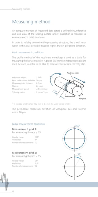
Twist parameters
Twist angle Dγ [º]
Angle between the peripheral direction and a twist structure.
The angle is oriented to the right (+ sign) when the direction of the
structure is from bottom right to top left. The angle is oriented to the
left (- sign) when the direction of the structure is from bottom left to
top right.
Twist depth Dt [µm]
Maximum vertical dimension between the wave peak and the wave
alley of the calculated twist surface.
Number of threads DG
Number of periods in peripheral direction referenced to 360°.
Theoretical supply cross section DF [µm2
]
Cross-sectional area of a period length in an axial section of the twist
surface.
Theoretical supply cross section DF per turn DFu [µm2
/U]
Cross-sectional area of a period length in an axial section of the twist
surface, multiplied by the number of threads.
Period length DP [mm]
Distance between two successive wave peaks or wave valleys in axial
direction.
Contact length in percent DLu [%]
A measure for the theoretical enclosure of the shaft surface in periphe-
ral direction by the sealing lip contact surface as a ratio of the total cir-
cumference. The calculation is made in a cutting depth corresponding
to a material ratio of the twist surface of 80 %.
The basis for determining the twist parameters is the measured
and accordingly filtered and calculated twist surface.](https://image.slidesharecdn.com/twistparametersen-150908221833-lva1-app6891/85/Twist-Parameters-Roughness-Measurement-10-320.jpg)


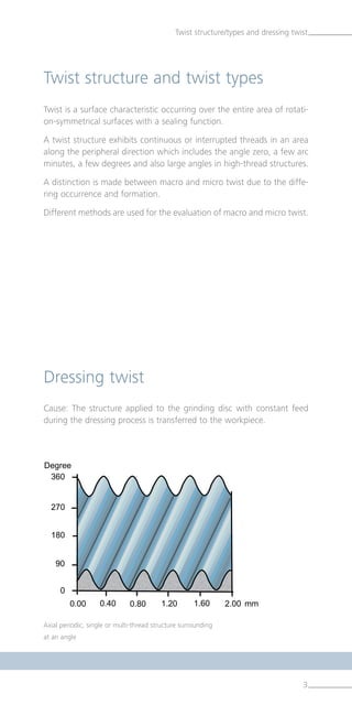
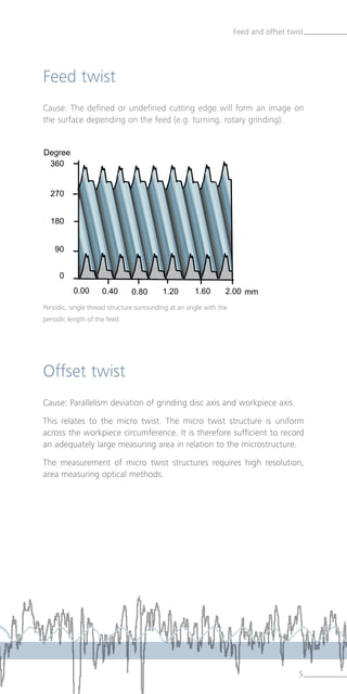
The document discusses the evolution and standards of twist measurement in shaft sealing applications, primarily highlighting the advancements made since Daimler's development of a uniform evaluation method in 1997. It outlines the technical specifications for measuring twist parameters, including various types of twist and appropriate measurement methods, alongside updates introduced in 2009. Additionally, it details the practical implications of these measurements in manufacturing processes, emphasizing the importance of surface texture in ensuring effective sealing functions.