Downloaded 351 times
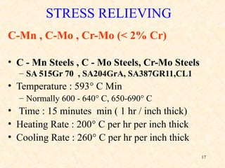
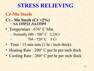
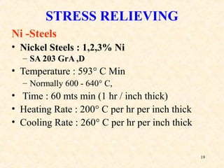
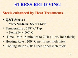
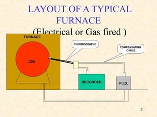
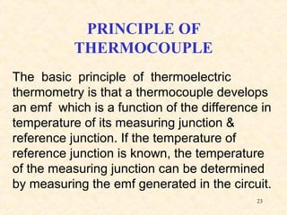
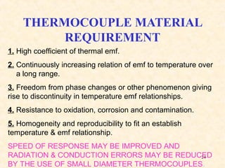
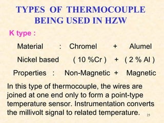
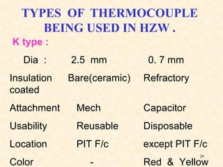
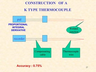
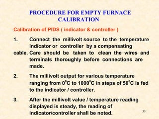
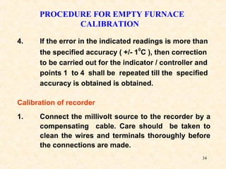
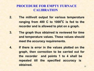
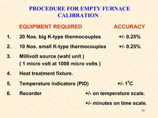


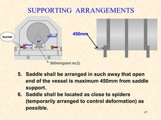
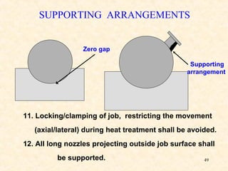
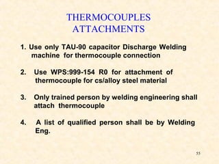
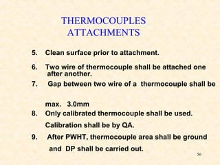
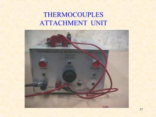

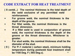
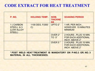
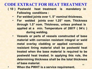
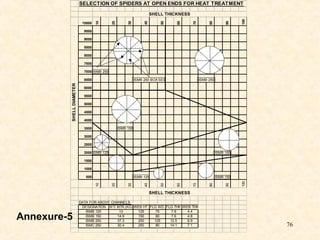
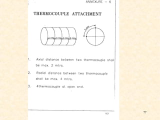
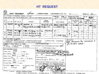


This document provides information about heat treatment of pressure vessels and various heat treatment processes. It discusses the effect of heat treatment on mechanical properties of metals and alloys. Various heat treatment processes like normalizing, annealing, stress relieving, solution annealing, hardening, tempering and aging are described. Parameters for heat treatment of different steel grades are listed. The document also covers thermocouples, recorders, furnace layout and calibration procedures for heat treatment furnaces.


