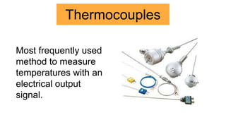
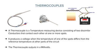
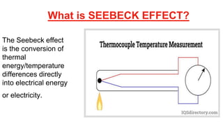
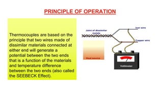
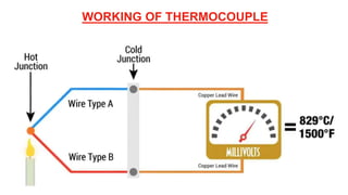
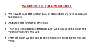
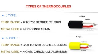
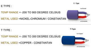
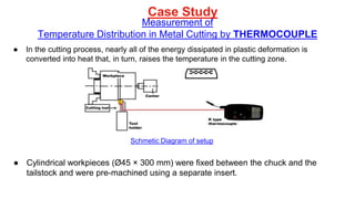
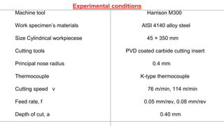
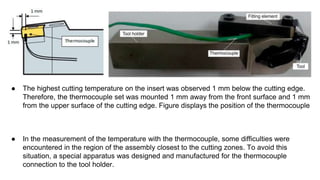
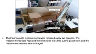
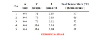
TEMPERATURE
MEASUREMENT
THERMOCOUPLE
PREPARED BY ------ MANAN GANDHI (20BME502)
Content : -
● Thermocouple
● SEEBECK EFFECT
● Principle of Thermocouple
● Working of Thermocouple
● Types of Thermocouple
● Case study & Conclusion
● Application
● Advantages and disadvantages
In Industry Various type of Temperature
measuring Devices such as,
Thermocouple
Thermistor
Resistance Temperature Detector (RTD).
Thermocouples
Most frequently used
method to measure
temperatures with an
electrical output
signal.
THERMOCOUPLES
➔ A Thermocouple is a Temperature measuring device consisting of two dissimilar
Conductors that contact each other at one or more spots.
➔ It produces a voltage when the temperature of one of the spots differs from the
reference temperature at other parts of the circuit
➔ The Thermocouple outputs in a Millivolts.
Thermocouple
Works on The
SEEBECK
EFFECT principle.
What is SEEBECK EFFECT?
The Seebeck effect
is the conversion of
thermal
energy/temperature
differences directly
into electrical energy
or electricity.
PRINCIPLE OF OPERATION
Thermocouples are based on the
principle that two wires made of
dissimilar materials connected at
either end will generate a
potential between the two ends
that is a function of the materials
and temperature difference
between the two ends (also called
the SEEBECK Effect).
WORKING OF THERMOCOUPLE
● We Have to keep Hot junction point at place where we have to measure
temperature.
● And keep cold junction at other side.
● Then due to temperature difference EMF will produce in the circuit and
voltmeter will show milli volt.
● From the graph we can able to see temperature based on the milli volt
value.
TYPES OF THERMOCOUPLES
● J TYPE :
TEMP RANGE = 0 TO 750 DEGREE CELSIUS
METAL USED = IRON-CONSTANTAN
● K TYPE :
TEMP RANGE = -200 TO 1250 DEGREE CELSIUS
METAL USED = NICKEL-CHROMIUM /ALUMINIUM
E TYPE :
TEMP RANGE = -200 TO 900 DEGREE CELSIUS
METAL USED =NICKEL-CHROMIUM / CONSTANTAN
T TYPE :
TEMP RANGE = -250 TO 350 DEGREE CELSIUS
METAL USED =COPPER - CONSTANTAN
Case Study
Measurement of
Temperature Distribution in Metal Cutting by THERMOCOUPLE
● In the cutting process, nearly all of the energy dissipated in plastic deformation is
converted into heat that, in turn, raises the temperature in the cutting zone.
● Cylindrical workpieces (Ø45 × 300 mm) were fixed between the chuck and the
tailstock and were pre-machined using a separate insert.
Schmetic Diagram of setup
Experimental conditions
Machine tool Harrison M300
Work specimen’s materials AISI 4140 alloy steel
Size Cylindrical workpiecese 45 × 350 mm
Cutting tools PVD coated carbide cutting insert
Principal nose radius 0.4 mm
Thermocouple K-type thermocouple
Cutting speed v 76 m/min, 114 m/min
Feed rate, f 0.05 mm/rev, 0.08 mm/rev
Depth of cut, a 0.40 mm
● The highest cutting temperature on the insert was observed 1 mm below the cutting edge.
Therefore, the thermocouple set was mounted 1 mm away from the front surface and 1 mm
from the upper surface of the cutting edge. Figure displays the position of the thermocouple
● In the measurement of the temperature with the thermocouple, some difficulties were
encountered in the region of the assembly closest to the cutting zones. To avoid this
situation, a special apparatus was designed and manufactured for the thermocouple
connection to the tool holder.
● The thermocouple measurements were recorded every five seconds. The
measurements were repeated three times for the same cutting parameters and the
measurement results were averaged.
EXPERIMENTAL RESULT
CONCLUSION
● As the speed increased, temperature of Cutting tool will increase & Feed rate
will not affect much more.
● Temperature at the tip of the Cutting tool is the highest.
● In the metal cutting industry, heat is generally dissipated by the discarded chip,
which carries away approximately 70%–80% of the total heat. The workpiece acts
as a heat sink drawing 10%–20% of the heat away and the cutting tool draws away
~10% of the heat.
www.mdpi.com/journal/sensors
1. Abukhshim, N.A.; Mativenga, P.T.; Sheikh, M.A. Investigation of heat partition in high speed
turning of high strength alloy steel. Int. J. Mach. Tools Manuf. 2005, 45, 1687–1695.
2. Abukhshim, N.A.; Mativenga, P.T.; Sheikh, M.A. Heat generation an temperature prediction in
metal cutting: A review and implications for high speed machining. Int. J. Mach. Tools Manuf.
2006, 46, 782–800.
3. Lowen, E.G.; Shaw, M.C. On the analysis of cutting tool temperatures. Trans. ASME 1954, 76,
217–231.
REFERENCES : -
APPLICATIONS
● Steel Industry
● Gas Appliance Safety
● Manufacturing
● Power Production
● Process Plants
ADVANTAGES
● It is rugged in construction
● Covers a wide temperature range
● Calibration can be easily checked
● High speed of response
● Satisfactory measurement accuracy
LIMITATIONS
● Thermocouples operation are relatively complex.
● The EMF induced vs temp characteristics is somewhat non-linear.
● Comparatively high in cost
THANK YOU

Temperature measurement (THERMOCOUPLE)

  • 1.
  • 2.
    Content : - ●Thermocouple ● SEEBECK EFFECT ● Principle of Thermocouple ● Working of Thermocouple ● Types of Thermocouple ● Case study & Conclusion ● Application ● Advantages and disadvantages
  • 3.
    In Industry Varioustype of Temperature measuring Devices such as, Thermocouple Thermistor Resistance Temperature Detector (RTD).
  • 4.
    Thermocouples Most frequently used methodto measure temperatures with an electrical output signal.
  • 5.
    THERMOCOUPLES ➔ A Thermocoupleis a Temperature measuring device consisting of two dissimilar Conductors that contact each other at one or more spots. ➔ It produces a voltage when the temperature of one of the spots differs from the reference temperature at other parts of the circuit ➔ The Thermocouple outputs in a Millivolts.
  • 6.
  • 7.
    What is SEEBECKEFFECT? The Seebeck effect is the conversion of thermal energy/temperature differences directly into electrical energy or electricity.
  • 8.
    PRINCIPLE OF OPERATION Thermocouplesare based on the principle that two wires made of dissimilar materials connected at either end will generate a potential between the two ends that is a function of the materials and temperature difference between the two ends (also called the SEEBECK Effect).
  • 9.
  • 10.
    WORKING OF THERMOCOUPLE ●We Have to keep Hot junction point at place where we have to measure temperature. ● And keep cold junction at other side. ● Then due to temperature difference EMF will produce in the circuit and voltmeter will show milli volt. ● From the graph we can able to see temperature based on the milli volt value.
  • 11.
    TYPES OF THERMOCOUPLES ●J TYPE : TEMP RANGE = 0 TO 750 DEGREE CELSIUS METAL USED = IRON-CONSTANTAN ● K TYPE : TEMP RANGE = -200 TO 1250 DEGREE CELSIUS METAL USED = NICKEL-CHROMIUM /ALUMINIUM
  • 12.
    E TYPE : TEMPRANGE = -200 TO 900 DEGREE CELSIUS METAL USED =NICKEL-CHROMIUM / CONSTANTAN T TYPE : TEMP RANGE = -250 TO 350 DEGREE CELSIUS METAL USED =COPPER - CONSTANTAN
  • 14.
    Case Study Measurement of TemperatureDistribution in Metal Cutting by THERMOCOUPLE ● In the cutting process, nearly all of the energy dissipated in plastic deformation is converted into heat that, in turn, raises the temperature in the cutting zone. ● Cylindrical workpieces (Ø45 × 300 mm) were fixed between the chuck and the tailstock and were pre-machined using a separate insert. Schmetic Diagram of setup
  • 15.
    Experimental conditions Machine toolHarrison M300 Work specimen’s materials AISI 4140 alloy steel Size Cylindrical workpiecese 45 × 350 mm Cutting tools PVD coated carbide cutting insert Principal nose radius 0.4 mm Thermocouple K-type thermocouple Cutting speed v 76 m/min, 114 m/min Feed rate, f 0.05 mm/rev, 0.08 mm/rev Depth of cut, a 0.40 mm
  • 16.
    ● The highestcutting temperature on the insert was observed 1 mm below the cutting edge. Therefore, the thermocouple set was mounted 1 mm away from the front surface and 1 mm from the upper surface of the cutting edge. Figure displays the position of the thermocouple ● In the measurement of the temperature with the thermocouple, some difficulties were encountered in the region of the assembly closest to the cutting zones. To avoid this situation, a special apparatus was designed and manufactured for the thermocouple connection to the tool holder.
  • 17.
    ● The thermocouplemeasurements were recorded every five seconds. The measurements were repeated three times for the same cutting parameters and the measurement results were averaged.
  • 18.
  • 19.
    CONCLUSION ● As thespeed increased, temperature of Cutting tool will increase & Feed rate will not affect much more. ● Temperature at the tip of the Cutting tool is the highest. ● In the metal cutting industry, heat is generally dissipated by the discarded chip, which carries away approximately 70%–80% of the total heat. The workpiece acts as a heat sink drawing 10%–20% of the heat away and the cutting tool draws away ~10% of the heat.
  • 20.
    www.mdpi.com/journal/sensors 1. Abukhshim, N.A.;Mativenga, P.T.; Sheikh, M.A. Investigation of heat partition in high speed turning of high strength alloy steel. Int. J. Mach. Tools Manuf. 2005, 45, 1687–1695. 2. Abukhshim, N.A.; Mativenga, P.T.; Sheikh, M.A. Heat generation an temperature prediction in metal cutting: A review and implications for high speed machining. Int. J. Mach. Tools Manuf. 2006, 46, 782–800. 3. Lowen, E.G.; Shaw, M.C. On the analysis of cutting tool temperatures. Trans. ASME 1954, 76, 217–231. REFERENCES : -
  • 21.
    APPLICATIONS ● Steel Industry ●Gas Appliance Safety ● Manufacturing ● Power Production ● Process Plants
  • 22.
    ADVANTAGES ● It isrugged in construction ● Covers a wide temperature range ● Calibration can be easily checked ● High speed of response ● Satisfactory measurement accuracy
  • 23.
    LIMITATIONS ● Thermocouples operationare relatively complex. ● The EMF induced vs temp characteristics is somewhat non-linear. ● Comparatively high in cost
  • 24.