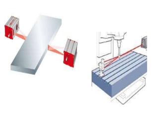
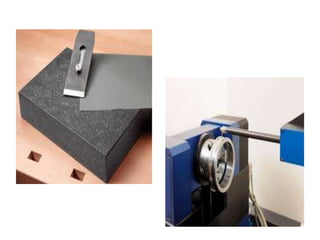
1. The document discusses various form measurement principles and methods including straightness, flatness, thread measurement, gear measurement, surface finish measurement, and roundness measurement.
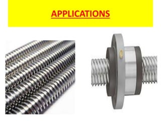
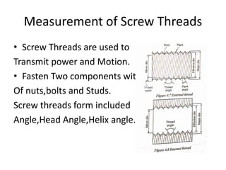
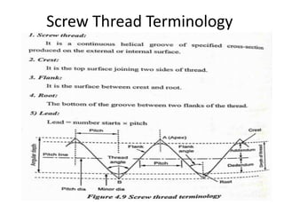
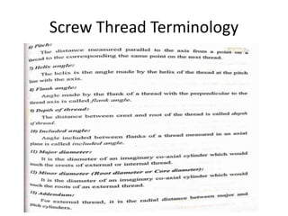
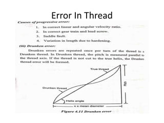
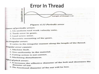
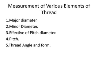
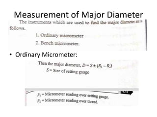
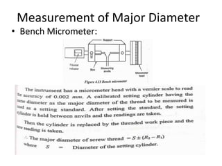
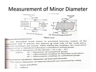
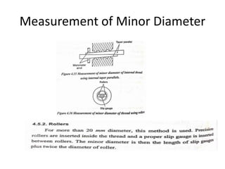
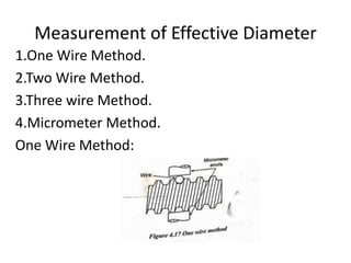
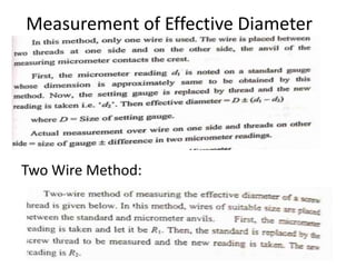
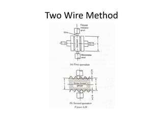
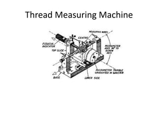
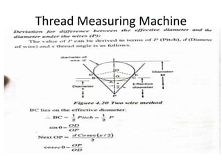
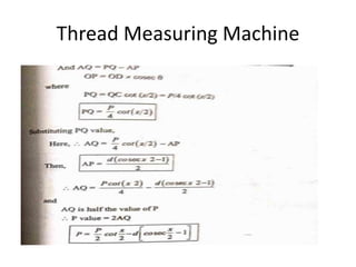
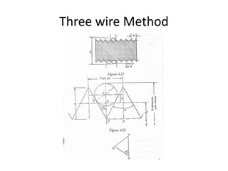
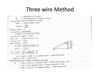
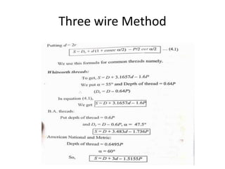
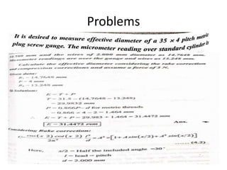
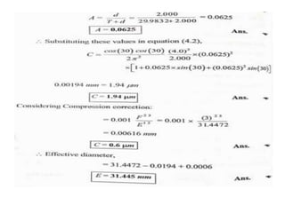
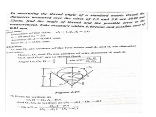
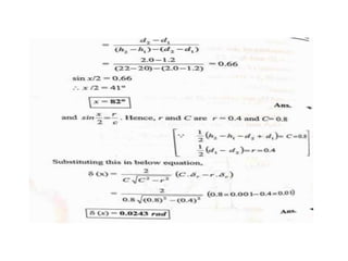
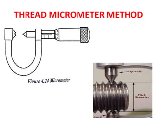
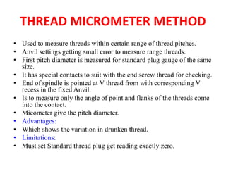
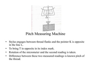
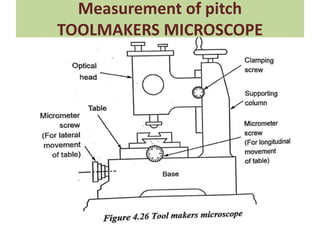
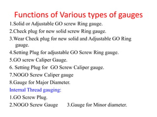
2. Thread measurement involves measuring various thread elements like major diameter, minor diameter, pitch, and form using methods such as thread plug gauges, thread wires, and thread micrometers.
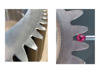
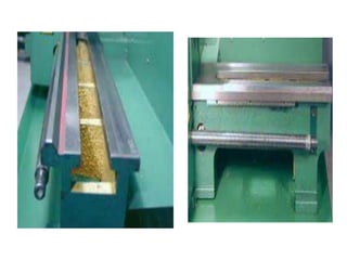
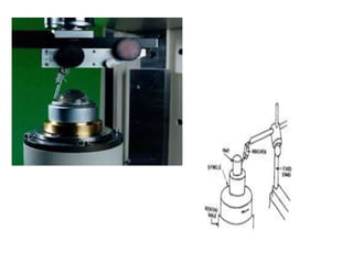
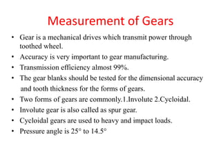
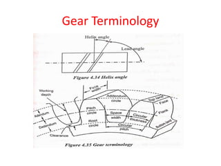
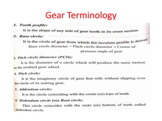
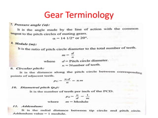
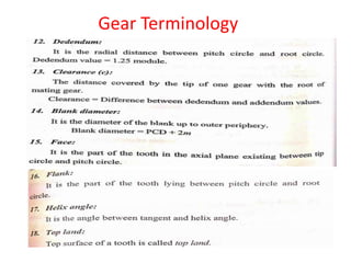
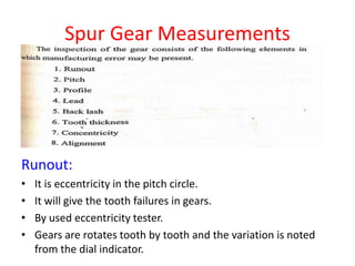
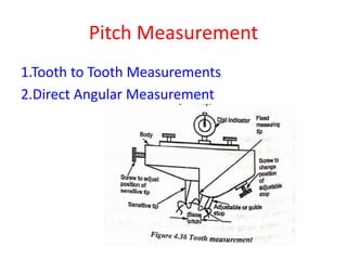
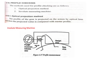
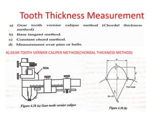
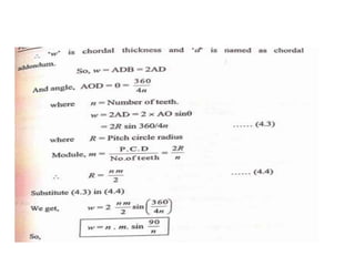
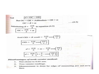
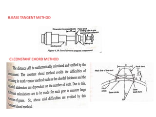
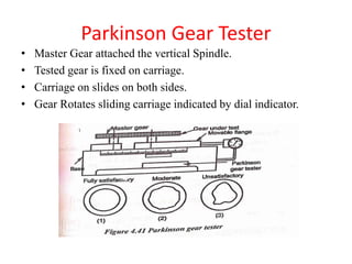
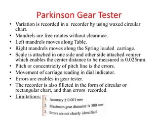
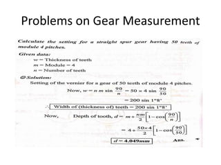
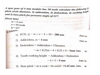
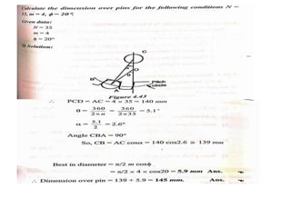
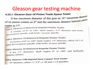
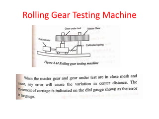
3. Gear measurement includes measuring parameters like pitch, lead, backlash, tooth thickness, and errors using equipment such as involute measuring machines, gear tooth vernier calipers, and gear testers.
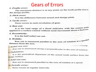
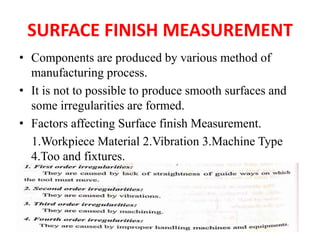
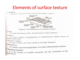
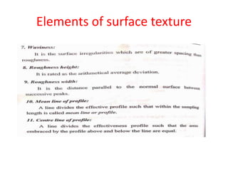
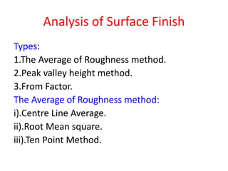
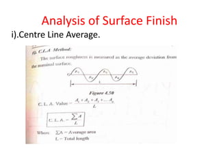
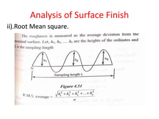
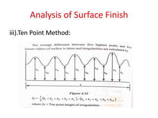
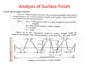
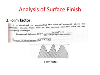
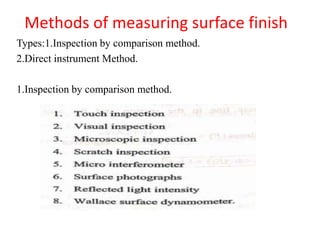
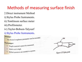
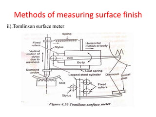
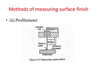
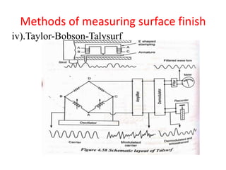
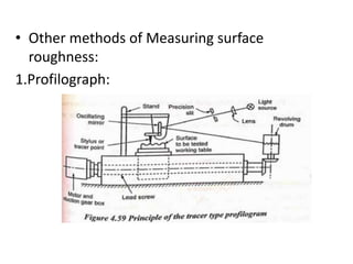
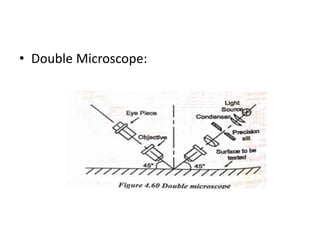
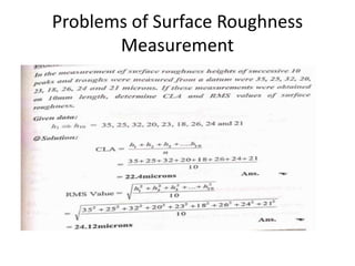
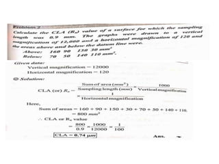
4. Surface finish is measured using techniques like stylus probes, profilometers, and comparisons to standard samples which analyze roughness parameters like Ra