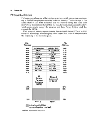
This document introduces microcontrollers and discusses the PIC microcontroller in particular. It defines a microcontroller as an inexpensive single-chip computer containing a CPU, memory, I/O lines, and other components. Microcontrollers are versatile because they can be programmed to perform unique tasks. The document promotes using PIC microcontrollers over Basic Stamps, citing that PIC programs run much faster and at a lower cost due to differences in how programs are stored and executed on each chip. It encourages learning to program PIC microcontrollers to gain advantages for circuit design.


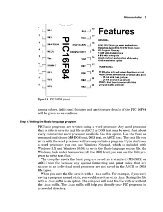

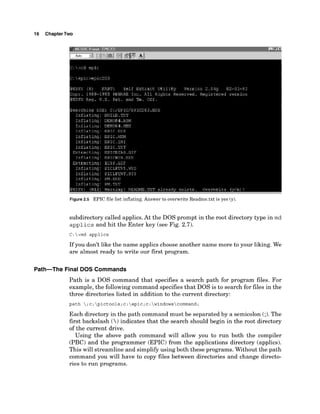

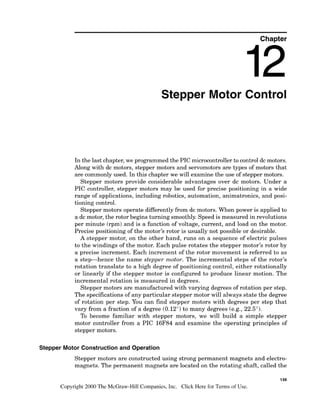
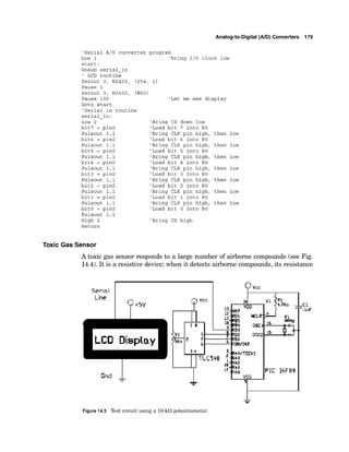
![76 Chapter Five
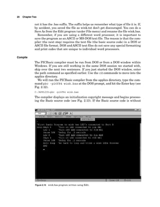
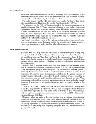
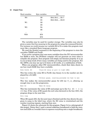
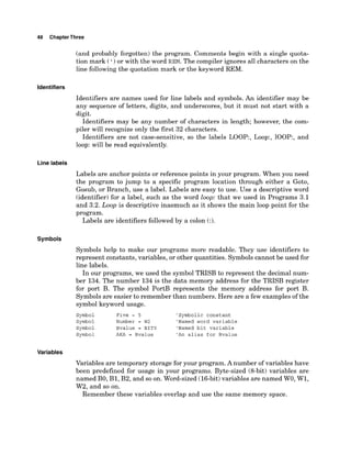
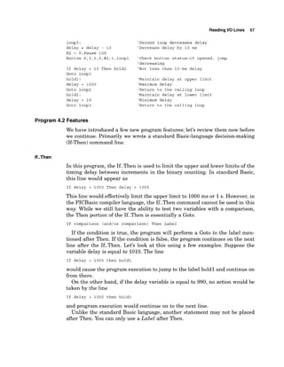
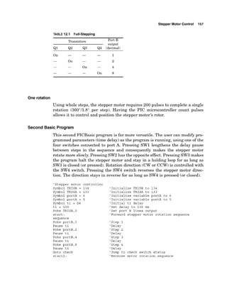
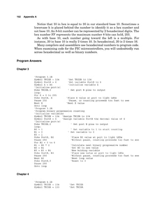
If Bit3 = 0 Then route1 'If RA4 is low, jump to route1
If Bit4 = 0 Then route1 'If RA5 is low, jump to route2
Goto loop
The example shows that bits may be checked for high or low status. The
Peek command also works with pins that are configured as outputs. When
peeked, the resultant shows the binary value that has been poked in the
port register.
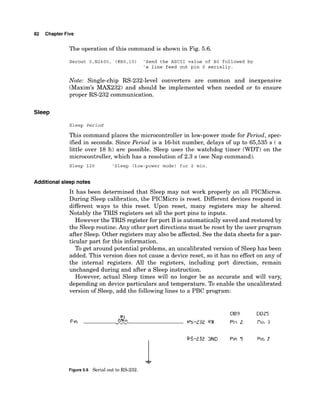
Poke
Poke Address, Variable
The Poke command can write to any of the microcontroller's registers at the
Address specified and copy the value in Varto the register. This command may
be used to write to special registers such as A/D converters and additional I10
ports.
Poke writes an entire byte (8bits) to the register at once.
Poke 134,O 'Write binary 0 to DDR for port B, making all pins
'output lines.
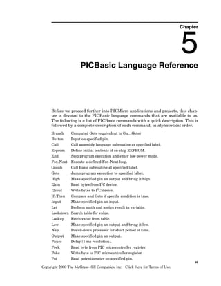
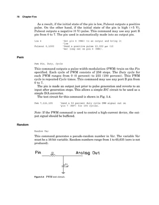
Pot
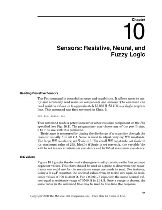
Pot Pin, Scale, Var
This command reads a potentiometer or other resistive transducer on the Pin
specified. The programmer may choose any of the port B pins, 0 to 7, to use
with this command.
Resistance is measured by timing the discharge of a capacitor through
the resistor, usually 5 to 50 kfl. Scale is used to adjust varying RIC con-
stants. For large RIC constants, set Scale to 1.For small RIC constants, set
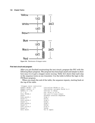
Scale to its maximum value of 255. Ideally, if Scale is set correctly, the vari-
able Var will be set to zero at minimum resistance and to 255 at maximum
resistance.
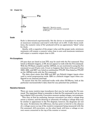
Scale must be determined experimentally. Set the device or transducer to
measure at maximum resistance and read it with Scale set to 255. Under
these conditions, Var will produce an approximate value for Scale.
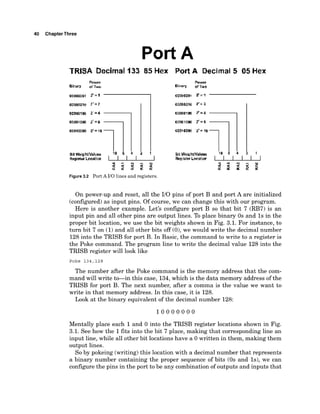
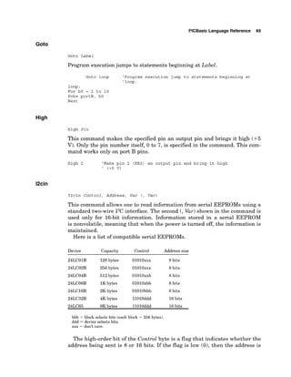
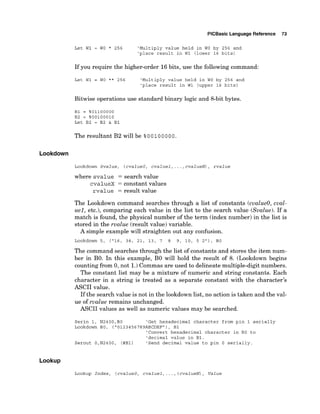
There are many resistive-type transducers that may be read using the Pot
command. The important thing that distinguishes this command from an ana-
log-to-digital (A/D)
converter is that a converter measures voltage, not resis-
tance. [Although the voltage drop across the converter may seem to be similar
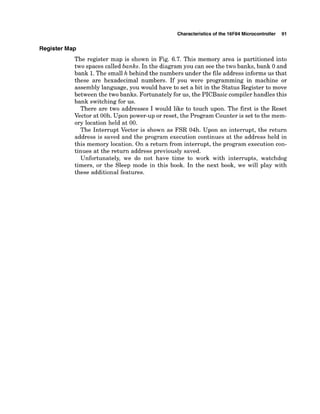
to the Pot diagram (Fig. 5.3), it is not.]
Pot 3,255,BO 'Read potentiometer on pin 3 to
'determine scale.
Serout O,N2400, (#BO) 'Send pot values out on pin 0
'serially.](https://image.slidesharecdn.com/ebook-elettronicapicmicrocontrollerprojectbook-231015112946-d4464a60/85/Ebook-Elettronica-Pic-Microcontroller-Project-Book-pdf-91-320.jpg)

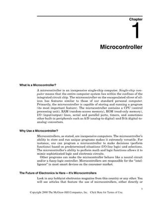
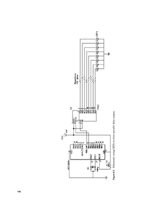
![104 Chapter Eight
Output First
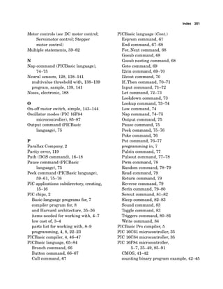
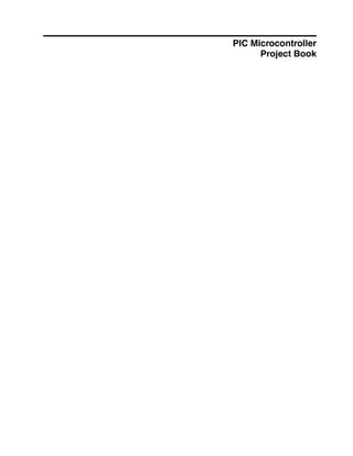
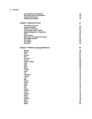
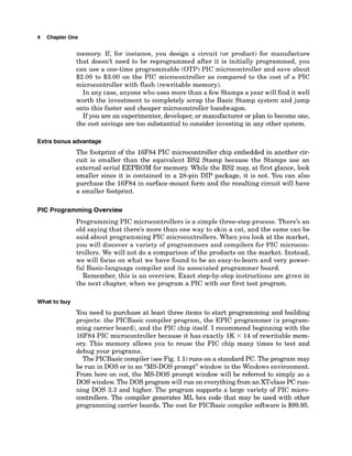
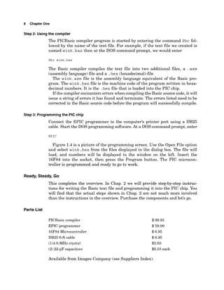
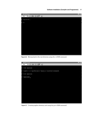
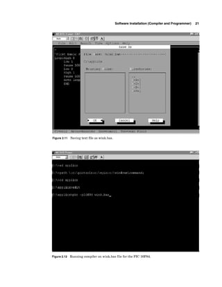
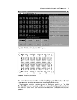
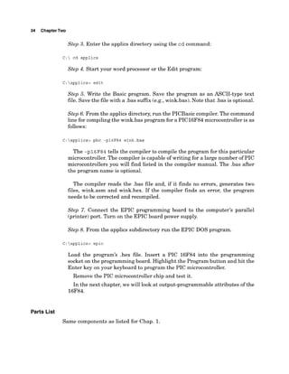
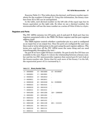
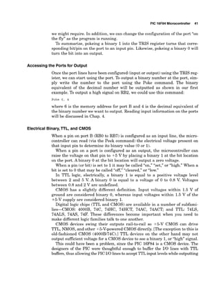
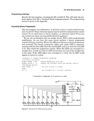
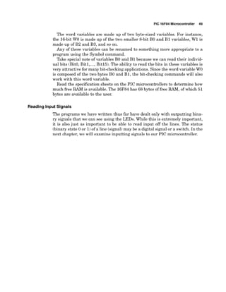
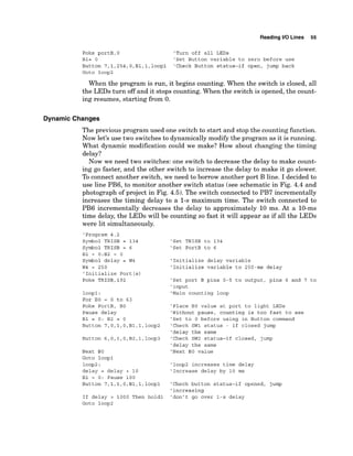
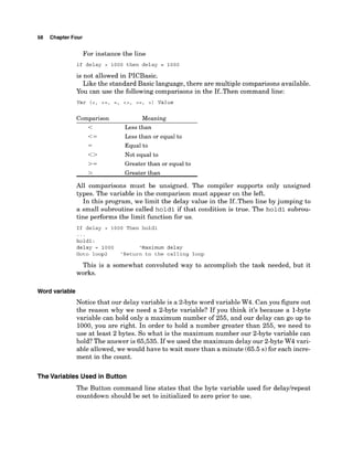
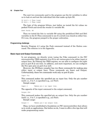
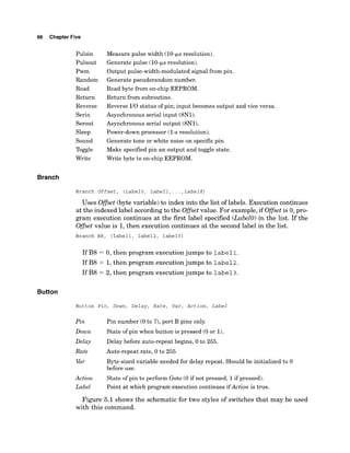
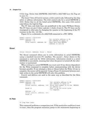
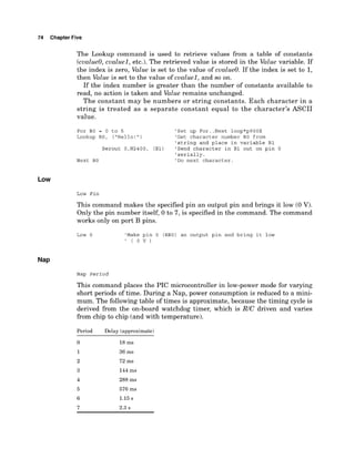
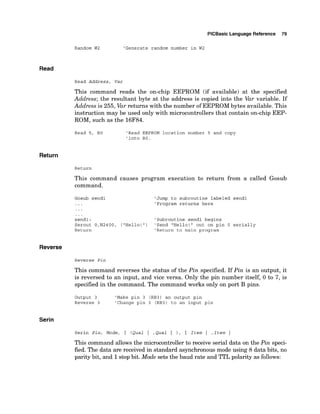
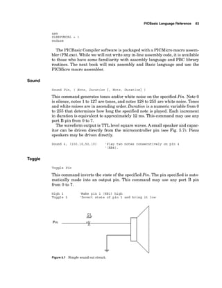
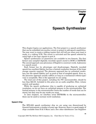
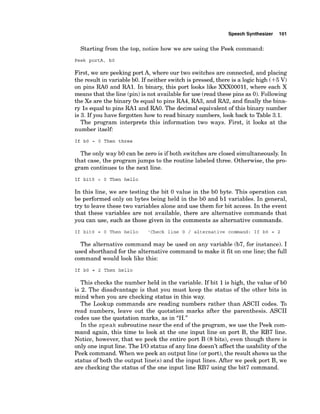
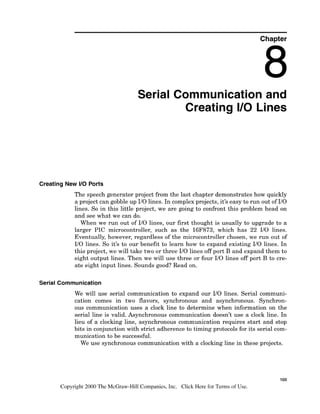
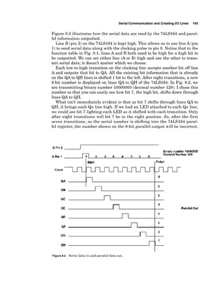
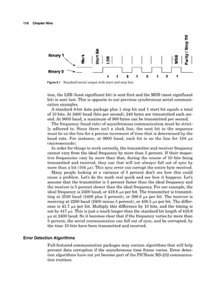
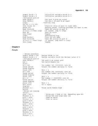
To create the output lines, we are going to use a serial-to-parallel converter
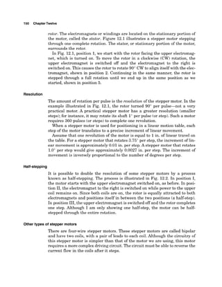
chip, the 74LS164 (seeFig. 8.1).This chip reads 8-bit serial data on pins 1and
2 and outputs the data on eight parallel lines (QAto QH).
If you remember from the command description of the Basic language
(Chap. 5),we have built-in Serin (serial in) and Serout (serial out) commands.
Unfortunately, we cannot use these Basic commands because their serial for-
mat uses stop and start bits. Start and stop bits are necessary in asynchronous
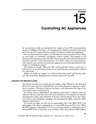
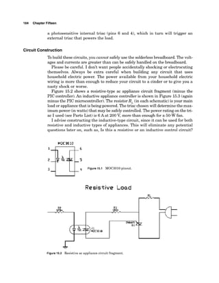
(without a clock)communication.
The 74LS164 converter chips use a clock line and do not use or require stop
and start bits. Since there is no way to remove these bits from the standard
serial Basic commands, we need to program our own serial communication.
Synchronous communication requires a clocking pulse. The clocking pulse
determines when the information on the serial line is valid. For the 74LS164,
it is on the low-to-hightransition of the clock pulse that information (value 0
or 1)on the serial line is valid.
Basic Serial
Serial data are transmitted most significant bit (bit 7)first. Since we are writ-
ing the serial routine, we could change this and send out the least significant
bit (bit 0)first if we wanted, but we will not; we will stay with this convention.
FUNCTION TABLE
I I I
H= hiah level L= low level
Clock
vcc L4
X = imlevant [any input including transitions]
?=Transitbn from low to high
Qa ...Qg =the level after bhle most recant tramition
of the clack; fndlcates a one bit shift
Figure 8.1 Pinout 74LS164 serial-to-parallel chip.
A B
Outputs
QAQH ...QH](https://image.slidesharecdn.com/ebook-elettronicapicmicrocontrollerprojectbook-231015112946-d4464a60/85/Ebook-Elettronica-Pic-Microcontroller-Project-Book-pdf-119-320.jpg)


![Index 199
A
AC adapters, 64
AC appliances control, 183-189
circuit construction guidelines for,
184-187
loads, inductivelresistive, 183-184
noses, electronic, 188
parts list for, 188-189
smart controls, 188
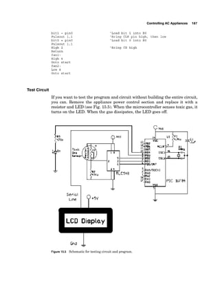
test circuit, 187
ND converters [seeAnalog-to-digital
converter(s)]
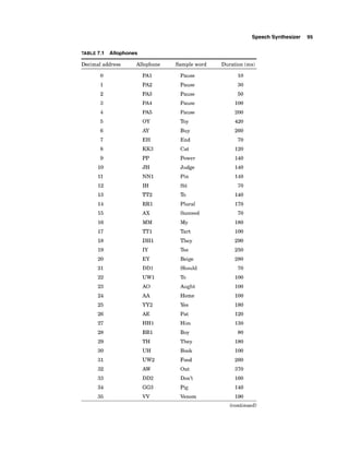
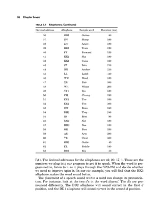
Allophones, 94-96
Alphanumeric display, LCD (see LCD
alphanumeric display)
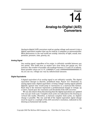
Analog-to-digital(AID)converter(s),175-18 1
and digital equivalents of analog
signal, 175
parts list for, 180
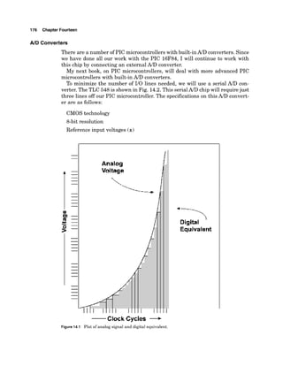
reference voltage, setting, 177
results, interpretation of, 178
serial chip controllsequence in,
178-179
specificationsfor, 176-177
toxic gas sensor example, 179-181
voltage rangelresolution for, 177-178
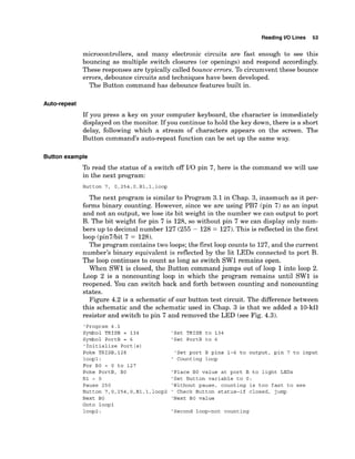
Auto-repeat, 53
B
Banks, 91
Basic language, 2
Basic Stamps, 2
Binary, 36,41-45
Bit shift correcting, 109-111
Bits, 36
Branch command (PICBasic
language), 66
Breadboard, solderless, 28-30
Button command (PICBasic language),
51-55,66-67
auto-repeat function of, 53
debounce features of, 52-53
example using, 53-55
Button command (Cont.):
structure of, 51
variables used in, 58-59
Bytes, 36
C
Call command (PICBasic language), 67
Central processing unit (CPU), 1, 2, 36
CMOS devices, 41-42
Comments, 47-48
Compiler software, 4-5, 8, 11-14
Cost of PIC chips, 3-4
CPU (see Central processing unit)
D
DC motor control, 143-147
bidirectional control, 144-146
diodes for, 146-147
on-off motor switch, simple,
143-144
parts list for, 147
transistor, choice of, 143
Debouncing, 52-53
Diodes:
in DC motor control, 146-147
in fuzzy logic sensors, 133, 134
Dynamic modification, 55-57
E
Eeprom command (PICBasic
language), 67
EEPROM memory, 2,3,93
Electrical binary, 41
End command (PICBasic language),
67-68
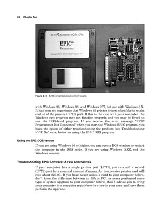
EPIC programming carrier board, 5, 6,
22-23
EPIC software:
installation of, 14-15
troubleshooting, 24-25
versions of, 23-24
Error detection algorithms,
118-119](https://image.slidesharecdn.com/ebook-elettronicapicmicrocontrollerprojectbook-231015112946-d4464a60/85/Ebook-Elettronica-Pic-Microcontroller-Project-Book-pdf-214-320.jpg)