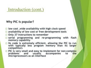
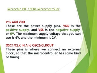
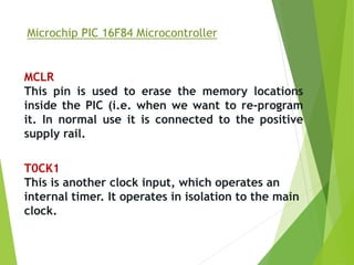
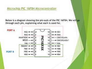
PIC microcontroller
ARAFAT,MD YASIN 12-22600-3
Muneem, Muhtasim Aziz 12-22751-3
Mazumder Shovon Kumar 12-22755-3
Hasan, Md. Akik Ibn 12-22470-3
Rahman, Md. Azazur 12-22816-3
Supervised by: RETHWAN FAIZ
An Introduction to PIC Microcontrollers
- The name PIC was originally an acronym for "Programmable
Intelligent Computer".
- A PIC microcontroller is a processor with built in memory and
RAM and you can use it to control your projects.
- What this really means for you is that you have a very powerful
device that has many useful built in modules e.g.
* EEPROM.
* Timers.
* Analogue comparators.
* UART.
Introduction (cont.)
 low cost ,wide availability with high clock speed
 availability of low cost or free development tools
 Only 37 instructions to remember
 serial programming and re-programming with flash
memory capability
 Its code is extremely efficient, allowing the PIC to run
with typically less program memory than its larger
competitors
 PIC is very small and easy to implement for non-complex
problems and usually accompanies to the
microprocessors as an interface
Why PIC is popular?
Microchip PIC 16F84 Microcontroller
Below is a diagram showing the pin-outs of the PIC 16F84. We will go
through each pin, explaining what each is used for.
Microchip PIC 16F84 Microcontroller
RA0 To RA4
RA is a bidirectional port. That is, it can be
configured as an input or an output. The number
following RA is the bit number (0 to 4). So, we
have one 5-bit directional port where each bit can
be configured as Input or Output.
RB0 To RB7
RB is a second bidirectional port. It behaves in
exactly the same way as RA, except there are 8 -
bits involved.
Microchip PIC 16F84 Microcontroller
VSS And VDD
These are the power supply pins. VDD is the
positive supply, and VSS is the negative supply,
or 0V. The maximum supply voltage that you can
use is 6V, and the minimum is 2V.
OSC1/CLK IN And OSC2/CLKOUT
These pins is where we connect an external
clock, so that the microcontroller has some kind
of timing.
Microchip PIC 16F84 Microcontroller
MCLR
This pin is used to erase the memory locations
inside the PIC (i.e. when we want to re-program
it. In normal use it is connected to the positive
supply rail.
T0CK1
This is another clock input, which operates an
internal timer. It operates in isolation to the main
clock.
Microchip PIC 16F84 Microcontroller
Below is a diagram showing the pin-outs of the PIC 16F84. We will go
through each pin, explaining what each is used for.
PORT A
PORT B
The Registers
A register is a place inside the PIC that can be written to, read from
or both.
you will notice is that it is split into two - Bank 0 and Bank
1. Bank 1 is used to control the actual operation of the PIC, for
example to tell the PIC which bits of Port A are input and which
are output. Bank 0 is used to manipulate the data.
An example is as follows: Let us say we want to make one bit on
Port A high. First we need to go to Bank 1 to set the particular bit,
or pin, on Port A as an output. We then come back to Bank 0 and
send a logic 1 (bit 1) to that pin.
The Registers
The most common registers in Bank 1 we are going to use are
STATUS, TRISA and TRISB. The first allows us to come back to Bank
0, TRISA allows us to select which pins on Port A are output and
which are input, TRISB allows us to select which pins on Port B are
output and which are input. The SELECT register in Bank 0 allows us
to switch to Bank 1.
STATUS
To change from Bank 0 to Bank 1 we tell the STAUS register. We do
this by setting bit 5 of the STATUS register to 1. To switch back to
Bank 0, we set bit 5 of the STATUS register to 0. The STATUS
register is located at address 03h.
PIC Peripherals
The PIC microcontroller has many built
in peripherals and this can make using them
quite daunting at first which is why I have made
this introductory page with a summary of each
major peripheral block.
PIC Peripherals
Flash memory
This is the program storage area and gives you the most important
benefit for using a PIC microcontroller - You program the device
many times.
PIC microcontroller RAM
The PIC microcontroller RAM size is also important as it stores all
your variables and intermediate data.
Note: You can usually alter the program to use less RAM by
choosing the right variable sizes or changing how your program
works
For example don't use floating point alter it to use a different
variable type e.g. you can use long integers with fixed point
operation to avoid floating point.
PIC Peripherals
PIC microcontroller EEROM
Electrically Erasable ROM is used to store data that must be saved
between power up and power down.
This area is readable and writable and has a much longer life than
the main program store i.e. it has been designed for more
frequent use.
PIC Peripherals
I/O Ports
Input / Output ports let you communicate with the outside world so
you can control leds, LCDs or just about anything with the right
interface. You can also set them as inputs to gather information.
Pin direction
Most PIC microcontroller pins can be set as an input or and output
and this can be done on the fly e.g. for a dallas 1 wire system a pin
can be written to generate data and read at a later stage. The TRIS
register controls the I/O direction and setting a bit in this register
to zero sets the pin as output while setting it as one sets the pin
as input.
EXAMPLE
16F84A
RB0
RB1
RA0
sbit pir at RA0_bit;
sbit led at RB0_bit;
sbit buzzer at RB1_bit;
void main() {
TRISA = 0b00000001;
TRISB = 0b00000000;
while(1){
if (pir=1){
led=1;
buzzer=1;
}
else{
led=0;
buzzer=0;
}
}
}
Define Components name
if-else Statement
Loop
I/O Declaration
THANK YOU
ALL

Presentation

  • 1.
    PIC microcontroller ARAFAT,MD YASIN12-22600-3 Muneem, Muhtasim Aziz 12-22751-3 Mazumder Shovon Kumar 12-22755-3 Hasan, Md. Akik Ibn 12-22470-3 Rahman, Md. Azazur 12-22816-3 Supervised by: RETHWAN FAIZ
  • 2.
    An Introduction toPIC Microcontrollers - The name PIC was originally an acronym for "Programmable Intelligent Computer". - A PIC microcontroller is a processor with built in memory and RAM and you can use it to control your projects. - What this really means for you is that you have a very powerful device that has many useful built in modules e.g. * EEPROM. * Timers. * Analogue comparators. * UART.
  • 3.
    Introduction (cont.)  lowcost ,wide availability with high clock speed  availability of low cost or free development tools  Only 37 instructions to remember  serial programming and re-programming with flash memory capability  Its code is extremely efficient, allowing the PIC to run with typically less program memory than its larger competitors  PIC is very small and easy to implement for non-complex problems and usually accompanies to the microprocessors as an interface Why PIC is popular?
  • 4.
    Microchip PIC 16F84Microcontroller Below is a diagram showing the pin-outs of the PIC 16F84. We will go through each pin, explaining what each is used for.
  • 5.
    Microchip PIC 16F84Microcontroller RA0 To RA4 RA is a bidirectional port. That is, it can be configured as an input or an output. The number following RA is the bit number (0 to 4). So, we have one 5-bit directional port where each bit can be configured as Input or Output. RB0 To RB7 RB is a second bidirectional port. It behaves in exactly the same way as RA, except there are 8 - bits involved.
  • 6.
    Microchip PIC 16F84Microcontroller VSS And VDD These are the power supply pins. VDD is the positive supply, and VSS is the negative supply, or 0V. The maximum supply voltage that you can use is 6V, and the minimum is 2V. OSC1/CLK IN And OSC2/CLKOUT These pins is where we connect an external clock, so that the microcontroller has some kind of timing.
  • 7.
    Microchip PIC 16F84Microcontroller MCLR This pin is used to erase the memory locations inside the PIC (i.e. when we want to re-program it. In normal use it is connected to the positive supply rail. T0CK1 This is another clock input, which operates an internal timer. It operates in isolation to the main clock.
  • 8.
    Microchip PIC 16F84Microcontroller Below is a diagram showing the pin-outs of the PIC 16F84. We will go through each pin, explaining what each is used for. PORT A PORT B
  • 9.
    The Registers A registeris a place inside the PIC that can be written to, read from or both. you will notice is that it is split into two - Bank 0 and Bank 1. Bank 1 is used to control the actual operation of the PIC, for example to tell the PIC which bits of Port A are input and which are output. Bank 0 is used to manipulate the data. An example is as follows: Let us say we want to make one bit on Port A high. First we need to go to Bank 1 to set the particular bit, or pin, on Port A as an output. We then come back to Bank 0 and send a logic 1 (bit 1) to that pin.
  • 10.
    The Registers The mostcommon registers in Bank 1 we are going to use are STATUS, TRISA and TRISB. The first allows us to come back to Bank 0, TRISA allows us to select which pins on Port A are output and which are input, TRISB allows us to select which pins on Port B are output and which are input. The SELECT register in Bank 0 allows us to switch to Bank 1. STATUS To change from Bank 0 to Bank 1 we tell the STAUS register. We do this by setting bit 5 of the STATUS register to 1. To switch back to Bank 0, we set bit 5 of the STATUS register to 0. The STATUS register is located at address 03h.
  • 11.
    PIC Peripherals The PICmicrocontroller has many built in peripherals and this can make using them quite daunting at first which is why I have made this introductory page with a summary of each major peripheral block.
  • 12.
    PIC Peripherals Flash memory Thisis the program storage area and gives you the most important benefit for using a PIC microcontroller - You program the device many times. PIC microcontroller RAM The PIC microcontroller RAM size is also important as it stores all your variables and intermediate data. Note: You can usually alter the program to use less RAM by choosing the right variable sizes or changing how your program works For example don't use floating point alter it to use a different variable type e.g. you can use long integers with fixed point operation to avoid floating point.
  • 13.
    PIC Peripherals PIC microcontrollerEEROM Electrically Erasable ROM is used to store data that must be saved between power up and power down. This area is readable and writable and has a much longer life than the main program store i.e. it has been designed for more frequent use.
  • 14.
    PIC Peripherals I/O Ports Input/ Output ports let you communicate with the outside world so you can control leds, LCDs or just about anything with the right interface. You can also set them as inputs to gather information. Pin direction Most PIC microcontroller pins can be set as an input or and output and this can be done on the fly e.g. for a dallas 1 wire system a pin can be written to generate data and read at a later stage. The TRIS register controls the I/O direction and setting a bit in this register to zero sets the pin as output while setting it as one sets the pin as input.
  • 15.
  • 16.
    sbit pir atRA0_bit; sbit led at RB0_bit; sbit buzzer at RB1_bit; void main() { TRISA = 0b00000001; TRISB = 0b00000000; while(1){ if (pir=1){ led=1; buzzer=1; } else{ led=0; buzzer=0; } } } Define Components name if-else Statement Loop I/O Declaration
  • 17.