Interfacing PIC Microcontrollers 2nd Edition Martin Bates
1.
Interfacing PIC Microcontrollers2nd Edition
Martin Bates pdf download
https://ebookgate.com/product/interfacing-pic-
microcontrollers-2nd-edition-martin-bates/
Get Instant Ebook Downloads – Browse at https://ebookgate.com
2.
Instant digital products(PDF, ePub, MOBI) available
Download now and explore formats that suit you...
PIC Microcontrollers An Introduction to Microelectronics
2nd Ed 2nd Edition Martin P. Bates
https://ebookgate.com/product/pic-microcontrollers-an-introduction-to-
microelectronics-2nd-ed-2nd-edition-martin-p-bates/
ebookgate.com
PIC Programming for Beginners Arrl
https://ebookgate.com/product/pic-programming-for-beginners-arrl/
ebookgate.com
PIC Microcontroller Projects in C Basic to Advanced 2nd
Edition Dogan Ibrahim (Auth.)
https://ebookgate.com/product/pic-microcontroller-projects-in-c-basic-
to-advanced-2nd-edition-dogan-ibrahim-auth/
ebookgate.com
MicroPython for Microcontrollers 1st Edition Günter
Spanner
https://ebookgate.com/product/micropython-for-microcontrollers-1st-
edition-gunter-spanner/
ebookgate.com
3.
Microcontrollers From AssemblyLanguage to C Using the
PIC24 Family 2nd Edition Bryan A. Jones
https://ebookgate.com/product/microcontrollers-from-assembly-language-
to-c-using-the-pic24-family-2nd-edition-bryan-a-jones/
ebookgate.com
Converged Multimedia Networks 1st Edition Juliet Bates
https://ebookgate.com/product/converged-multimedia-networks-1st-
edition-juliet-bates/
ebookgate.com
Embedded Microcomputer Systems Real Time Interfacing 3rd
Edition Jonathan W. Valvano
https://ebookgate.com/product/embedded-microcomputer-systems-real-
time-interfacing-3rd-edition-jonathan-w-valvano/
ebookgate.com
Microcontroller Programming The Microchip PIC 1st Edition
Julio Sanchez
https://ebookgate.com/product/microcontroller-programming-the-
microchip-pic-1st-edition-julio-sanchez/
ebookgate.com
Calculus and Vectors 12 1st Edition Bryce Bates
https://ebookgate.com/product/calculus-and-vectors-12-1st-edition-
bryce-bates/
ebookgate.com
Interfacing PIC Microcontrollers
EmbeddedDesign by Interactive Simulation
Martin Bates
AMSTERDAM • BOSTON • HEIDELBERG • LONDON
NEW YORK • OXFORD • PARIS • SAN DIEGO
SAN FRANCISCO • SINGAPORE • SYDNEY • TOKYO
Newnes is an imprint of Elsevier
7.
Newnes is animprint of Elsevier
The Boulevard, Langford Lane, Kidlington, Oxford OX5 1GB, UK
225 Wyman Street, Waltham, MA 02451, USA
First edition 2008
Second edition 2014
Copyright r 2014 Martin Bates and Elsevier Ltd. All rights reserved
No part of this publication may be reproduced, stored in a retrieval system,
or transmitted in any form or by any means, electronic, mechanical, photocopying,
recording, or otherwise, without the prior written permission of the publisher.
Permissions may be sought directly from Elsevier’s Science & Technology Rights
Department in Oxford, UK: phone (144) (0) 1865 843830; fax (144) (0) 1865 853333;
email: permissions@elsevier.com. Alternatively you can submit your request online
by visiting the Elsevier web site at http://elsevier.com/locate/permissions, and selecting
Obtaining permission to use Elsevier material.
Notice
No responsibility is assumed by the publisher for any injury and/or damage to persons
or property as a matter of products liability, negligence or otherwise, or from any
use or operation of any methods, products, instructions or ideas contained in the material
herein. Because of rapid advances in the medical sciences, in particular, independent
verification of diagnoses and drug dosages should be made.
British Library Cataloguing-in-Publication Data
A catalogue record for this book is available from the British Library.
Library of Congress Cataloging-in-Publication Data
A catalog record for this book is availabe from the Library of Congress.
ISBN: 978-0-08-099363-8
For information on all Newnes publications
visit our Web site at store.elsevier.com
Typeset by MPS Limited, Chennai, India
www.adi-mps.com
Printed in the UK
14 15 16 17 10 9 8 7 6 8 4 3 2
8.
Preface
The PIC isone of the biggest selling small microcontrollers. When it first became
available, it was not only technically innovative, but helped to make the teaching of
microelectronics much more interesting. A small controller with flash memory meant that a
great variety of student projects could be realised quickly and easily. It helped that the
development toolkit was free as well.
It has always been a problem in electronics that you cannot see a circuit working in the
same way that a mechanical engineer can see a steam engine pumping up and down.
Sure, we can see the screen flickering on a television, or an electric motor spinning, but
you cannot see electrons or volts directly. As a result, it has always been that bit more
difficult to learn electronics.
Interactive electronic design software is the answer. The Proteus VSM (Virtual System
Modelling) software used in this book has been developed by Labcenter Electronics in the
UK. It brings circuits to life on the computer screen and makes learning electronics more
effective and more fun. It is also a full-scale professional product, and will take the student
electronic engineer seamlessly into commercial design work.
This book is intended to support electronic learning wherever it takes place, at college,
at work or in the home. Please enjoy!
Martin Bates
March 2013
xiii
9.
Introduction
This book isthe second edition of the sequel to ‘PIC Microcontrollers, an Introduction
to Microelectronics’, which attempted to provide introduction to the subject via a single
type of microcontroller. It explores the basic techniques for connecting the PIC to
peripheral devices and the outside world. It shows how to connect simple input and output
devices, such as switches, sensors, displays and motors, as well as demonstrating
communication methods that allow the PIC to communicate data with other devices,
including intelligent sensors. The second edition has been extensively revised, updated
and expanded.
A domestic inkjet printer is an example of a product that contains a range of sensors,
drives and displays. It typically has a wireless data link to receive the page data, at least
two motors to feed the paper and position the print head, and a microcontroller to output
the signals to the print cartridge inkjets and generally coordinate the action. Take an old
one apart and have a look! Another good example is the digital camera. In fact, most small
electronic products contain a microcontroller that provides its core functions. A smoke
detector with a PIC microcontroller is shown in Figure I.1.
The PICr
microcontroller was the first widely available device to use flash memory,
which made it ideal for prototyping and experimental work. Flash memory, as used in
memory cards and sticks, allows the application program to be replaced quickly and easily
with a new version. Cheap flash memory microcontrollers have also transformed the
teaching of microelectronics they are re-usable and the internal architecture is fixed,
making them easier to understand. The small instruction set of the PIC is also a major
advantage there are only 35 instructions to learn in the main microcontroller unit (MCU)
used in this book.
The free development system MPLABr
provided by Microchip Inc.r
is another reason
for using the PIC range. In addition to the program editor and project management features,
it includes a text-based simulator which allows the program to be tested prior to
downloading, potentially saving a lot of time debugging in hardware. However, this only
tests the program itself, not the circuit in which it is connected.
xv
10.
Proteusr
from Labcenter Electronicsr
allowsa PIC to be simulated in circuit. It consists
of two main parts, ISIS and ARES. ISIS is the schematic capture and interactive simulation
package used to create the circuit schematic and to test the circuit prior to building
the real hardware. On-screen buttons and virtual signal sources provide inputs to the circuit.
Output (analogue or digital) can be displayed on a signal probe, a virtual instrument
or graph. An MCU can be dropped on the screen, the circuit drawn, a program attached
and tested immediately on screen.
When the application is working correctly in simulation mode, a PCB can be designed
by exporting a netlist (list of components and connections) from ISIS into the ARES layout
package. The resulting PCB files can be output to a production system or sent to a
specialist manufacturer. The final stage is then to assemble the board and test the hardware.
After using Proteus VSM, it should work first time!
This book is built around particular devices and tools, because it allows specific examples
to be used. It is assumed that at a later stage, with more experience, the reader will be
able to evaluate these against competing products and choose the most appropriate for any
given design task. Each topic is illustrated by designs based on the well-established PIC
16F877A, but it will be replaced in the readers’ own designs with a more recent device
such as the 16F887 chip.
All the circuits are available on the support website www.picmicros.org.uk. All schematics
were produced using ISIS and you can produce them to the same standard in your
Figure I.1
Smoke detector with PIC controller.
xvi Introduction
11.
own reports. Themicrocontroller models can be purchased in packages for institutional or
professional use from www.labcenter.com. Currently, a Proteus starter kit including models
for the PIC 16F84A, 16F877A and 18F452 can be purchased for only d150.
Microchip provides an extensive range of demonstration and development kits to support
their microcontroller product range see www.microchip.com for all product details.
A basic development kit is illustrated in Figure I.2, which consists of a prototyping target
board, a selection of hardware components including some small PIC chips, programmer
module and development system software that is loaded onto a host PC. A circuit is
built on the prototyping area, for example a motor interface, and a suitable PIC chip fitted
into one of the sockets on the board. The motor control program can be written in MPLAB
on the host computer, debugged in MPSIM, the Microchip simulator, downloaded to the
target board and the hardware tested.
However, it is preferable to test the application before constructing the hardware, in case
changes are needed. It is much quicker and easier to change the circuit, or the program,
on screen, rather than in hardware. ISIS allows the program to be entered, assembled and
attached to the on-screen chip for interactive testing within the virtual circuit. A typical
simulation screen is shown in Figure I.3.
The book is structured in three parts. Part 1 reviews PIC microcontroller architecture and
programming, Part 2 introduces PIC interfacing techniques and Part 3 covers PIC system
design and implementation.
Prototyping
target board
Programmer
module
Prototype
circuit
components
Host
development
software
Programmer
connector
Figure I.2
PICDEM development kit. Courtesy of Microchip Inc.
Introduction xvii
12.
In Chapter 1,a standard PIC microcontroller, the 16F877A, is described in detail, based
mainly on its data sheet. Chapter 2 outlines the programming process, using only MPLAB
tools, and Chapter 3 describes the application development process using Proteus VSM.
In Chapter 4, basic input and output devices are introduced, while Chapter 5 describes
the techniques for data representation and conversion, Chapter 6 covers all aspects
of analogue signal conditioning and, in Chapter 7, power output interfacing is introduced,
concentrating on motor drives.
Chapter 8 outlines the operation of the main PIC serial communication ports, and Chapter 9
describes a wide range of sensors for monitoring and measurement applications. Chapter 10
concludes with a consideration of MCU selection and the principles and practice of system
design.
The book was originally designed to support project development by students at all levels.
It may therefore sometimes state what is obvious to more experienced engineers; hopefully
this is not too irritating, and they too will find something of interest within!
Figure I.3
Base board simulation screenshot.
xviii Introduction
13.
Links and Acknowledgements
SupportWebsite
www.picmicros.org.uk
Author’s website with related PIC books and application file downloads
Follow the link to demo applications in INTAPPS2.ZIP containing:
• VSM project file app2.pdsprl
• PIC source code app2.asm (in MCU folder)
• PIC debug file debug.cof (in MCU folder)
Labcenter Electronics
www.labcenter.com
Manufacturer and supplier of Proteus VSM electronic design system
• Download demo version of VSM
• Purchase MCU package licence
• Tutorials and product information
Microchip Technology Inc.
www.microchip.com
Manufacturer of the PIC microcontroller range and MPLAB IDE
• Download data sheets
• Information on development tools
• Download MPLAB development system
Custom Computer Services Inc.
www.ccsinfo.com
Manufacturer and supplier of PIC CCS ‘C’ Compilers
Please search online by name for product datasheets other than Microchip.
Use of all manufacturers’ trademarks and data is gratefully acknowledged.
Thanks in particular to Iain Cliffe at Labcenter Electronics.
xix
replacement in newdesigns. The reason for continuing to use the ‘877A’ in this edition
of the book is that it is still available as a part of a low-cost simulation package that
is suitable for students and hobbyists on a budget and has all the main interfaces that are
still used in current chips. In any event, when designing a new application, a chip should
always be selected from the available range which most closely matches the design
requirements at minimum cost, so prototyping with a chip with surplus capabilities is a
useful approach. It can be replaced at a later design stage with a chip that matches
more closely with the system requirements.
A big advantage of the PIC is that the programming language is relatively simple,
as compared with microprocessors such as the Intel series used in the PC. These have a
powerful, but complex, instruction set to support a wide range of multimedia applications.
The supporting documentation for the PIC MCU range is also clear and well laid out, and a
development system, for writing and testing programs, can also be downloaded free from
the Microchip website (www.microchip.com).
1.1 Processor System
The microcontroller contains the same main elements as any computer system, namely:
• Central Processor Unit (CPU)
• Data storage (memory) devices
• Input and output ports
In a PC, these features are generally implemented as separate chips, linked together
through bus connections on a complex printed circuit board, under the control of
the microprocessor. A bus is a set of lines which carry data in parallel form which
are shared by the peripheral devices. This type of system can be tailored to suit a
particular application, with the type of CPU, size of memory, and selection of input and
output (I/O) devices matched to the system requirements. However, even in real-time
applications, it has been common for some time to use a standard board based on the
Intel processor system running a generic operating system (often Windows and its
derivatives). The basic microprocessor system is conveniently summarised in a block
diagram (Figure 1.1) which shows the data flow between the main elements using
shared bus lines.
In the microcontroller, all these basic elements are on one chip. This means that the
MCU for a particular application must be chosen from the available range to suit its
operational requirements. In any given circuit, the microcontroller also tends to have a
single, specific function. This type of product is frequently referred to as an embedded
application.
4 Chapter 1
16.
1.1.1 Processor
In amicroprocessor system or a microcontroller, a single processor block is in charge of all
input, output, calculations and control. It cannot operate without a program, a list of
instructions that is held in memory. The program consists of a sequence of binary codes that
are fetched from memory by the CPU and executed in turn (Figure 1.2). The process is driven
by a crystal clock circuit producing a fixed frequency that determines the speed of the system.
The instructions are stored in numbered memory locations and copied to an instruction
register in the CPU, via a data bus. Here, the instruction controls the selection of the
Program memory
CPU
Instruction register
Decoder logic
Execution logic
Control lines to system
Data bus
Address bus
Program
counter
Address Instruction
0000 10010011
0001 01010001
0002 10000100
0003 00011001
0004 01011100
0005 xxxxxxxx
0006 xxxxxxxx
etc etc
Figure 1.2
Microprocessor program execution.
CPU
Memory
Output
Input
Figure 1.1
Block diagram of a basic microprocessor system.
PIC Hardware 5
17.
required operation withinthe control unit of the processor. The program codes are found
in memory by the processor by outputting the address number of the instruction on an
address bus. The address is generated in the program counter, a register which starts at zero
and is incremented or modified during each instruction cycle. The busses are parallel
connections which transfer the address or data word in one operation. A set of control lines
from the CPU is also needed to assist with this process; these are set up according to
the requirements of the current instruction and trigger the data transfer circuits to output
and receive the data at the appropriate time. In the conventional microprocessor system,
the bus connections consist of parallel tracks on a motherboard but are internal in the
microcontroller chip.
Decoding the instruction is a hardware process, using a block of logic gates to set up the
control lines of the processor unit, and to fetch the instruction ‘operands’. The operands
are data to be operated on (or information about where to find it) which follow most
instructions. Typically, a calculation or logical operation is carried out on the operands,
and a result stored back in memory, or an I/O action set-up. Each complete instruction
may be one, two or more bytes long, which includes the operation (instruction) code itself
(op-code) and the operand/s (one byte 5 8 bits).
For example, compare a word processor and games application. In the word processor,
keystrokes are read in via the input keyboard port, stored as character codes in memory and
sent to a screen output port for display. In a computer game, input signals from the control
pad are processed and used to modify the screen graphics. The graphics are basically
generated by mapping a memory block to the screen where the colour of one pixel is
controlled by a particular data word. The word processor needs far less memory, and the
graphics memory has to be large and fast.
1.1.2 Memory
There are two main types of microprocessor memory, volatile and non-volatile. ROM
(Read Only Memory) is non-volatile and retains its data when switched off. In the PC, the
main working memory is volatile RAM (Read and Write Memory), normally implemented
as plug-in DIMM (Dual In-line Memory Module) modules, which carry a set of dynamic
RAM chips. These are used by the CPU to store current working application files and data.
RAM originally meant Random Access Memory, referring to the data read-and-write
mechanism, but ROM is accessed in exactly the same way, using row and column addresses
to identify each storage cell.
In a traditional PC design, a small ROM chip is used to get the system started when it is
switched on; it contains the BIOS (Basic Input Output System) program. However, the
main operating system (OS), e.g. Windowst, and application program, e.g. Wordt, have
6 Chapter 1
18.
to be loadedinto RAM from hard disk drive (HDD), which takes some time, as you may
have noticed! So why not put the OS in ROM, where it would be instantly available?
Well, RAM is faster, cheaper and more compact, and the OS can be changed or upgraded
on disk. In addition, an OS such as Windows is large compared with the size of RAM
generally installed, so elements are only loaded into RAM as needed. Numerous
applications can also be stored on disk and loaded only as required.
The ideal memory is non-volatile, read and write, fast, large and cheap. Unfortunately,
it does not exist! Therefore, we have a range of memory technologies as shown in
Table 1.1, which have different advantages. These are used in combination in the PC
to provide the optimum overall performance for a given cost. This also depends on the
application being run at any one time. The main trade-off is cost, size and speed of
access.
Flash ROM, as used in memory sticks and MP3 players, is closest to the ideal, having the
advantages of being non-volatile and rewritable. This is why it is used as program memory
in microcontrollers which need to be reprogrammable, such as the PIC 16F877A. The
microcontroller uses flash program memory because it is usually dedicated to a particular
control task that does not need a large amount of working data storage. The working data
registers in the PIC can therefore be implemented as a relatively small block of static RAM
(SRAM). As flash ROM technology has improved, conventional one-time programmable
ROM has now generally been rendered superfluous but is included for completeness in the
comparison.
Table 1.1: Memory and Data Storage Technologies.
ROM
(Read Only
Memory)
Flash
ROM
RAM (Read and
Write Memory)
CD-ROM
(Compact
Disk-ROM)
DVD-RW
(Digital Versatile
Disk-Read and
Write)
HDD (Hard
Disk Drive)
Feature Chip Chip Module Optical disk Optical disk Magnetic disk
Typical size
128kb 256Mb 2Gb 650Mb 4.7Gb 250Gb
Non-volatile Yes Yes No Yes Yes Yes
Write Once Many Many Once Many Many
Size Poor OK OK Good Good Good
Expandability OK OK Good None None None
Cost per bit Poor OK Good Good Good Good
Speed of access OK Good Good Poor Poor Poor
1 byte 5 8 bits
1kb 5 1 kilobyte 5 1024 bytes
1Mb 5 1 megabyte 5 1024kb
1Gb 5 1 gigabyte 5 1024Mb
PIC Hardware 7
19.
1.1.3 Input andOutput
Without some means of getting information and signals in and out, a data processing or
digital control system would not be very useful. Input and output ports generally contain a
port data register and a set of control registers that allow data to pass in and out. Serial
ports often use standard protocol (method of communication) to format the data.
In a PC, the keyboard, screen and mouse interfaces are the main I/O channels, supported by
network, USB, SD Card and disk interfaces. The DIMM memory module has a parallel
connector (typically 64 bits), so it attaches directly to the processor busses. This means that
access is fast, because complete data blocks can be transferred at one time. USB on the
other hand is a serial bus, so data transfer can only occur one bit at a time, which is
inherently slower.
Microcontroller ports are generally more basic, especially in the smaller MCUs which
cannot accommodate the complex hardware needed for, say, a network port. The basic MCU
port consists of a group of 8 bits that can operate as a parallel port, but whose individual
pins have alternate functions, often several. The basic parallel operation is straightforward,
with an 8-bit data register that holds the I/O data, and an 8-bit data direction register whose
individual bits control the data direction, in or out. In the PIC, 0 5 output and 1 5 input.
Alternate functions are selected in the MCU control registers at set-up.
In principle, the parallel port is faster that the serial port but uses more pins to transfer
the data. The serial interface must organise the data in groups of bits for transmission.
Dedicated registers are used to organise the data stream and control the timing of the data
transfer. The serial port is based on a shift register that converts between parallel data on
the internal data bus and serial data on the peripheral line. The general principles of parallel
and serial data transfer are shown in Figure 1.3. The block arrows represent the 8-bit
internal data bus.
(a)
Parallel port register
Internal
data bus
External data lines
Read/write
control
Read/write
control
External
data line
Serial port register
Internal
data bus
(b)
Figure 1.3
(a) Parallel and (b) serial data ports.
8 Chapter 1
20.
In the parallelport operating in output mode, the data byte is loaded from the internal
data bus under the control of a read/write pulse from the CPU. The data can then
be seen on the output pins by the peripheral line. For testing, a logic probe, logic
analyser or just a simple LED indicator can be used. In input mode, data presented
at the input pins from a set of switches or other data source is latched into the
register when the port is read and is then available on the data bus for collection by
the CPU. One of the functions of the port is to separate the internal data bus from
the external hardware, and another is to temporarily store the data. The data can
then be transferred to memory, or otherwise processed, as determined by the CPU
program.
The serial port register also loads data from the internal bus in parallel but then sends it out
one bit at a time, operating as a shift register. If an asynchronous serial format is used, such
as RS232, start and stop bits are added so that bytes can be separated at the receiving end.
An error check bit is also available, to allow the receiver to detect corrupt data. In receive
mode, the register waits for a start bit and then shifts in the data at the same speed as it is
sent. This means the clock rate for the send and receive port must be the same. The
USART (Universal Synchronous/Asynchronous Receive/Transmit) port, which provides
RS232, will be described in more detail later.
A USB or network port is a more sophisticated version of the basic serial port and
arranges the data bytes in packets of, perhaps, 1k bytes. These are sent in a form which is
self-clocking, meaning that there is a transition within each bit (1 or 0), which triggers the
bit read into the receiving register. This is synchronous data transmission. An error
correction code follows the data, which allows mistakes to be corrected, rather than just
detected. This reduces the need for retransmission of incorrectly received data, as required
by simple error detection. Addressing information preceding the data allows multiple
receivers to be used.
The PIC 16F877A does not have USB or network interfaces built in, so we can avoid
detailed consideration of these complex protocols. It does nevertheless have a range of
other interfaces that will be discussed in detail and sample programs are provided. If further
explanation of the basics of microcontroller operation is required, the reader is invited to
refer to the introductory text ‘PIC Microcontrollers’ by the author.
1.2 PIC Architecture
Microcontrollers contain all the components required for a processor system in one chip:
CPU, memory and I/O. A complete system can therefore be built using one MCU chip and
a few I/O devices such as a keypad, display and other interfacing circuits. We will now see
how this is done in practice in our typical microcontroller.
PIC Hardware 9
21.
1.2.1 PIC 16F877APin Out
Let us first consider the pins that are seen on the IC package, and then we can discover
how they relate to the internal architecture. The chip can be obtained in different packages,
such as conventional 40-pin PDIP (Plastic Dual In-Line Package), square surface mount or
socket format. The PDIP version, shown in Figure 1.4, is easier for prototyping.
The I/O pins are arranged as 5 ports: A (5), B (8), C (8), D (8) and E (3), giving a total of
32 I/O pins. These can all operate as simple digital I/O pins but mostly have more than one
function, and the mode of operation of each is selected by initialising various control
registers within the chip. Note, in particular, that Ports A and E become ANALOGUE
INPUTS by default (on power-up or reset), so they have to set up for digital I/O if required.
The ports which have fewer than 8 bits have corresponding unused bits in their 8-bit data
and control registers.
Port B is used for downloading the program to the chip flash ROM, with RB7 receiving the
program code in serial form and RB6 receiving a clock which strobes each data bit into
the serial register on RB7. MCLR is taken to about 14V to initiate programming mode and
supply the programming voltage. RB3 can optionally be used in low-voltage programming
mode which does not require the 14V supply. Changes on RB0 and RB4RB7 can generate
an interrupt, which forces a change in the program sequence. Port C gives access to timers
and serial ports, while Port D can be used as a slave port, with Port E providing the control
pins for this function. All these options will be explained in detail later.
Reset = 0, Run = 1(Vpp)
Port A, Bit 0 (Analogue AN0 in)
Port A, Bit 1 (Analogue AN1in)
Port A, Bit 2 (Analogue AN2 in)
Port A, Bit 3 (Analogue AN3 in)
Port A, Bit 4 (Timer 0 I/O)
Port A, Bit 5 (Analogue AN4 in)
Port E, Bit 0 (AN5, Slave control)
Port E, Bit 1 (AN6, Slave control)
Port E, Bit 2 (AN7, Slave control)
+5V Power Supply
0V Power Supply
(CR clock) XTAL circuit
XTAL circuit
Port C, Bit 0 (Timer 1 I/O)
Port C, Bit 1 (Timers 1 2)
Port C, Bit 2 (Timer 1 I/O)
Port C, Bit 3 (SPI Clock)
Port D, Bit 0 (Slave I/O)
Port D, Bit 1 (Slave I/O )
MCLR
RA0
RA1
RA2
RA3
RA4
RA5
RE0
RE1
RE2
VDD
Vss
CLKIN
CLKOUT
RC0
RC1
RC2
RC3
RD0
RD1
1
2
3
4
5
6
7
8
9
10
11
12
13
14
15
16
17
18
19
20
40
39
38
37
36
35
34
33
32
31
30
29
28
27
26
25
24
23
22
21
RB7
RB6
RB5
RB4
RB3
RB2
RB1
RB0
VDD
Vss
RD7
RD6
RD5
RD4
RC7
RC6
RC5
RC4
RD3
RD2
Port B, Bit 7 (Prog. Data, Interrupt)
Port B, Bit 6 (Prog. Clock, Interrupt))
Port B, Bit 5 (Interrupt)
Port B, Bit 4 (Interrupt)
Port B, Bit 3 (LV Program)
Port B, Bit 2
Port B, Bit 1
Port B, Bit 0 (Interrupt)
+5V Power Supply
0V Power Supply
Port D, Bit 7 (Slave I/O)
Port D, Bit 6 (Slave I/O)
Port D, Bit 5 (Slave I/O)
Port D, Bit 4 (Slave I/O)
Port C, Bit 7 (USART Receive / Data)
Port C, Bit 6 (USART Transmit / Clock)
Port C, Bit 5 (I2C Data Out)
Port C, Bit 4 (I2C Data In / SPI Data)
Port D, Bit 3 (Slave I/O)
Port D, Bit 2 (Slave I/O)
Figure 1.4
PIC 16F877A pin out.
10 Chapter 1
22.
The chip hastwo pairs of power pins, where we usually assume VDD 5 15 V and
VSS 5 0 V. The chip can actually work down to about 2V supply, for battery and power
saving operation. A low-frequency clock circuit using only a capacitor and resistor to set
the frequency can be connected to CLKIN, or a crystal oscillator circuit can be connected
across CLKIN and CLKOUT. MCLR is the reset input; when cleared to 0, the MCU stops
and restarts when MCLR 5 1. This input must be tied high, allowing the chip to run if an
external reset circuit is not connected, but it is usually a good idea to incorporate a manual
reset button in all but the most trivial applications, as it allows the program to be restarted
if there is a problem.
1.2.2 PIC 16F877A Architecture
A block diagram of the 16F877A architecture is given in the manufacturer’s data sheet
(downloadable from www.microchip.com), Figure 1.2. A somewhat simplified version is
shown in Figure 1.5, which emphasises the program execution mechanism.
The main program memory is flash ROM, which stores a list of 14-bit instructions. These
are fed to the execution unit and used to modify the RAM file registers. These include
special control registers, the port registers and a set of general purpose registers which can
be used to store data temporarily. A separate working register (W) is used with the
Arithmetic Logic Unit (ALU) to hold the current data. Various special peripheral modules
provide a range of I/O options.
There are 512 RAM File Register addresses (01FFh), which are organised in 4 banks
(03), each bank containing 128 addresses (Table 1.2). The default (selected on power-up)
Bank 0 is numbered from 0 to 7Fh, Bank 1 from 80h to FFh and so on. All banks contain
both Special Function Registers (SFRs), which have a dedicated purpose, and the General
Purpose Registers (GPRs) that act as data RAM. The SFRs have labels that are specified in
the file that is normally combined with the user program. The relevant bank must be
selected in the user program to access the SFRs and GPRs (see Chapter 2).
The SFRs are shown in the block diagram as separate from the GPRs, but they are in fact
in the same address block. If the SFRs are deducted from the total number of RAM locations
(allowing for some registers which are repeated in more than one bank), 368 GPRs are
available for user data. The port registers are part of the main RAM block, found at specific
SFR addresses, e.g. Port D is at address 08h. If a review of hexadecimal and binary
numbering is required, refer to Chapter 5.
1.2.3 The PIC Instruction
The PIC program is written as a source code (a simple text file) on a PC host computer.
Any text editor can be used, but an editor is usually provided with the development system.
PIC Hardware 11
23.
We will assumeMPLAB is being used initially. The instructions are selected from the pre-
defined PIC instruction set detailed in Table13.2 in the PIC 16F877A data sheet and summarised
in the next chapter in Table 2.4. The demo program listed as Program 2.1 in the same chapter
shows the general format. Note that the original source code is preceded on each line by the
hexadecimal machine code which is downloaded to program memory. The source code file is
saved as PROGNAME.ASM in a suitable folder on the host PC.
The source code is assembled (converted to machine code) by the assembler program
MPASM, which creates the list of binary instruction codes. As this is displayed as
Flash
program
memory
8192
x14 bits
0000 – 1FFF
Instruction
register (14)
File select
register (8)
Working
register (8)
ALU
*Status
register (8)
MCU
control
lines
EEPROM
(256 bytes)
Data bus
(8 bits)
*Ports, timers
ADC, serial I/O
A(6) B(8) C(8) D(8) E(3)
Clock, timing and
programming control
Reset
Clock
Instruction
decode and
control
Program counter
(13 bits)
RAM
file
registers
368
bytes
000-1FF
Stack
8 levels
x13 bits
Address (13)
Instructions (14)
File address (7)
Literal (8)
Status bits
Op-code
*Part of file register set.
Figure 1.5
16F877A program execution block diagram.
12 Chapter 1
hexadecimal numbers, itis stored by the assembler with the extension PROGNAME.HEX.
This is then downloaded from the PC host to the MCU in the application board via a
programming module such as the PICkit3 shown in Figure I.1. This is plugged into the
USB port of the host and onto a set of 6 pins on the target board that are connected to the
programming pins of the MCU. The hex code is then transferred in serial form into the
PIC flash program memory.
The ‘877A’ has 8k of program memory, i.e. it can store a maximum of 8192 14-bit
instructions, usually starting at address 0. The highest address in this memory is therefore
1FFFh. In real-time applications, the program runs continuously and loops back at the end
to repeat the process. Let us look at a typical instruction to see how it works in relation
to the internal architecture:
Source code: MOVLW 05A
Hex code: 305A (4 hex digits)
Binary code: 0011 0000 0101 1010 (16 bits)
Instruction: 11 00xx kkkk kkkk (14 bits)
The instruction MOVLW means Move a Literal (a given number, in this case 5Ah) into the
Working register (W). The source code therefore consists of the mnemonic MOVLW and
operand 05Ah. This assembles into the hex code 305Ah (see Chapter 5 for number-type
conversion) and is stored in binary program memory as 11 0000 0101 1010. Since each hex
digit represents four binary bits, the leading two bits are set to zero to fill the first two bits.
In the instruction set, it can be seen that the first 4 bits (11 00) are the instruction code, the
next two are unused (xx, appearing as 00 in the binary code) and the last 8 are the literal
value (5Ah). The literal is represented as ‘kkkk kkkk’ since it can have any value from
00000000 to 11111111 (00hFFh).
The exact format of the PIC instructions depends on the number of bits required for the
operand (data to be processed). The number of op-code bits can vary from 3 to 14,
depending on the number of bits needed for the operand. This is different from a
conventional processor, such as the Pentium, where the op-code and operand are separate
and consist of a whole number of bytes. The PIC instruction is more compact, as is the
instruction set itself, for greater code efficiency; it is therefore known as an RISC (Reduced
Instruction Set Computer) chip.
1.3 Special Function Registers
As we have seen, the file register set is divided into SFRs and GPRs. The SFRs have
predetermined functions, as specified in the 16F877A data sheet (Figure 2.3). They
occupy locations 001F in Bank 0, 809F in Bank 1, 10010F in Bank 2 and 18018F in
Bank 3. The most frequently used are accessible in more than one bank, i.e. it is not necessary
14 Chapter 1
26.
to switch banksto read or write these registers. The most frequently used SFRs control some
aspect of program execution, but most of the rest are used to set up specific port functions.
1.3.1 Program Counter
The program counter (PCL 5 02h) keeps track of program execution by storing the address
of the current instruction. The ‘877A’ has 8k of program memory, so each location needs
a 13-bit address. PCL contains the low 8 bits of the program counter, while the upper bits
(PC , 812.) are accessed via PCLATH. PCL is incremented during each instruction,
and the contents replaced during a GOTO, CALL (program address) or RETURN (stack).
PCL can be modified directly, for example to implement a data table, but the high bits
are only writable indirectly via PCLATH. This causes some complications when making
long jumps, or writing the PCL directly, because the program memory is effectively divided
into 256 byte blocks and 2k pages (see Chapter 2).
1.3.2 Status Register
The status register (STATUS5 03h) records the result of certain operations and contains the
file register bank selection bits. The individual bit functions are summarised in Table 1.3.
1.3.2.1 Zero Flag (Z)
This is set (to 1) when the result of a register operation is zero and cleared (to 0) when it
is not zero. The full instruction set must be consulted to confirm which operations affect the
Z flag, but it is essentially most register operations. Bit test and skip instructions use this
flag for conditional branching, and there are also instructions that perform decrement
or increment and skip if zero in one operation as this is such a common requirement. An
example of the use of the zero flag is to check if two numbers are the same by subtracting
and applying bit test and skip to the Z bit.
Table 1.3: 16F877A File Register Set.
Bit Label Active Name Function
0 C 1 or 0 Carry bit Records carry or rotate out of file register MSB or LSB
1 DC 1 Digit Carry Records carry out of bit 3 in arithmetic operation
2 Z 1 Zero bit Records a zero result in any file register
3 PD 0 Power Down Cleared when SLEEP instruction has been executed
4 TO 0 Time Out Set when watchdog timer has expired
5 RP0 1 or 0 Bank Select 0 Low bank select bit used in direct addressing
6 PR1 1 or 0 Bank Select 1 High bank select bit used in direct addressing
7 IRP 1 or 0 Bank Select Bank select bit used in indirect addressing
PIC Hardware 15
27.
1.3.2.2 Carry Flag(C)
This flag is only affected by add, subtract and rotate instructions. If the result of an add
operation generates a carry out, that is, when two 8-bit numbers give a 9-bit sum, this flag
is set. The carry bit must then be included in subsequent calculations to give the
right result. When subtracting, the carry flag must be set initially, because it provides the
borrow digit (if required) in the most significant bit of the result. If the carry flag is cleared
after a subtraction, it means the result was negative, because the number being subtracted
was the larger. An example of this is seen later in the calculator program (Chapter 6).
Taken together, the zero and carry flags allow the result of an arithmetic operation to be
detected as positive, negative or zero, as shown in Table 1.4. Remember that the carry flag
must be set before a subtract operation; a borrow can then be detected as C 5 0.
1.3.2.3 Digit Carry (DC)
A file register can be seen as containing 8 individual bits, or 1 byte. It can also be defined
as two 4-bit nibbles (a small byte!), high and low. Each nibble can be represented as 1 hex
digit (0-F). The digit carry records a carry from the most significant bit of the low nibble
(bit 3). Hence, the digit carry allows 4-bit hexadecimal arithmetic to be implemented in the
same way that 8-bit binary arithmetic uses the carry flag C. Each nibble can also store a
BCD (binary coded decimal) number, values 09, for BCD arithmetic (see Chapter 5).
1.3.2.4 Register Bank Select (RP1, RP0)
The PIC 16F877A file register RAM is divided into four banks of 128 locations, Banks 03.
Only one can be selected at a time, depending on the settings of the register select bits RP0
and RP1 in the status register (Table 1.5). At power on reset, Bank 0 is selected by
default; when access to a register in Bank 1, 2 or 3 is required, these bits must be changed
accordingly and changed back afterwards. This can be done using BSF and BCF instructions.
Only the bit/s that need changing are set or cleared to switch between banks.
The supplementary instruction BANKSEL can be used instead. The operand for BANKSEL
is any register in the required bank or its label. BANKSEL detects the bank bits in the register
Table 1.4: Testing Arithmetic Results.
Flag After Operation Zero Carry Result Comment
(clear Carry) 0 0 A 1 B , 256 8-bit sum, no carry
ADD 1 1 A 1 B 5 256 Exactly, carry out
A 1 B 0 1 A 1 B . 256 9-bit sum, carry out
(set Carry) 0 1 A 2 B , 256 8-bit difference, no borrow
SUBTRACT 1 1 A 2 B 5 0 Numbers equal, no borrow
A 2 B 0 0 A 2 B , 0 Borrow taken, result negative
16 Chapter 1
28.
address and copiesthem to the status register bank select bits (see LED2 source code in the
next chapter, Program 2.1).
It can be seen that some registers repeat in more than one bank, making it easier and
quicker to access them, because bank switching is unnecessary. For example, the status
register repeats in all banks. In addition, a block of GPRs at the end of each bank repeat,
so that their data contents are available without changing banks. More recent PIC chips
avoid this problem by using linear addressing of the register memory space.
1.3.2.5 Power Status Bits (PD, TO)
The Power-Down (PD) bit is cleared to zero when SLEEP mode is entered. The Time Out
(TO) bit is cleared when the watchdog timer expires. These bits can then be used to trigger
suitable actions when these events occur.
1.3.3 Ports
The five ports in the PIC 16F877A, labelled AE, occupy SFR addresses 05h09h.
All pins can be used as bit or byte oriented digital input or output. Most of them also have
alternate functions as summarised in Table 1.6. The 16F887 has a similar set of alternate
functions, without the parallel slave port but with additional analogue inputs. In general, the
physical size of a PIC chip depends on the number of port pins provided.
It can be seen that many of the port pins have two or more functions controlled by the
initialisation of the relevant control registers. On power-up or reset, the port control register
bits adopt a default condition (see Table 2.1 in the data sheet, right-hand columns). The
TRISx (data direction) register bits in Bank 1 default to 1, setting the Ports B, C and D as
Table 1.5: Register Bank Selection.
Bank Select Codea
Addressh Totald Function
0 BCF 03,0
BCF 03,1
0020 32 SFRs
207F 96 GPRs
1 BSF 03,0
BCF 03,1
809F 32 SFRs, some repeat
A0EF 80 GPRs
F0FF 16 Repeat 707F
2 BCF 03,0
BSF 03,1
10010F 16 SFRs, some repeat
11016F 96 GPRs
17017F 16 Repeat 707F
3 BSF 03,0
BSF 03,1
18018F 16 SFRs, some repeat
1901EF 96 GPRs
1F01FF 16 Repeat 707F
Overall 0001FF 96
368
SFRs
GPRs
a
Or use BANKSEL.
PIC Hardware 17
29.
inputs. If thisis as required, no further initialisation is needed, since other relevant control
registers are generally reset to provide plain digital I/O by default.
However, there is an IMPORTANT exception. Ports A and E are set to ANALOGUE
INPUT by default, because the analogue control register ADCON1 in Bank 1 defaults to
0xxx0000. To set up these ports for digital I/O, this register must be loaded with the code
xxxx011x (x 5 don’t care or undefined), say 06h. If analogue input is required only on
selected pins, ADCON1 can be initialised with bit codes that give a mixture of analogue
and digital I/O on Ports A and E. Note that ADCON1 is in Bank 1, so BANKSEL is needed
to access it. Initialisation for analogue I/O will be explained in more detail later.
1.3.4 Timers
The simple way of creating a delay in a program is a software counting loop, as seen in
Program 2.1 (LED2.ASM) in Chapter 2. However, this is an inefficient use of MCU
resources, as the processer is completely occupied by the delay count. To avoid this problem,
the PIC 16F877A has three hardware timers (data sheet, Sections 5, 6 and 7). These are used
to carry out timing operations simultaneously with the main program execution, for faster and
more efficient overall performance. A typical timer function would be to generate a regular
pulse sequence at an output. A hardware timer count can be set to run and interrupt the MCU
when done (see interrupts below), which can then toggle the output.
Timer0 uses an 8-bit register, TMR0, file register address 01. Its output is the overflow
flag, T0IF, bit 2 in the Interrupt Control Register INTCON, address 0Bh. The timer register
Table 1.6: 16F877A Port Alternate Functions.
Bits Pins Alternate Function/s Bit Default
Port Aa
6 RA0RA5 Analogue inputs 0,1,2,3,5 Analogue Input
Timer0 clock input 4
Serial port slave select input 5
Port Ba
8 RB0RB7 External interrupt 0 Digital I/O
Low-voltage programming input 3
Serial programming 6,7
In-circuit debugging 6,7
Port C 8 RC0RC7 Timer1 clock input/output 0,1 Digital I/O
Capture/Compare/PWM 1,2
SPI, I2
C synchronous clock/data 3,4,5
USART asynchronous clock/data 6,7
Port Da
8 RD0RD7 Parallel slave port data I/O 07 Digital I/O
Port E 3 RE0RE2 Analogue inputs 0,1,2 Analogue Input
Parallel slave port control bitsa
0,1,2
a
16F887 Port A: Additional comparator inputs RA0RA5.
Port B: Additional analogue inputs RB0RB5.
Port D: Parallel slave port not present, RD5RD7 PWM outputs.
18 Chapter 1
30.
is incremented viaa clock input that is derived from either the MCU oscillator (fOSC) or
an external pulse train at RA4. The register counts from 0 to 255 in binary, then rolls over
to 00 again, at which point T0IF is set.
If the internal clock is used, the register acts as a timer. Each instruction in the
MCU takes four clock cycles to execute, so the instruction clock is fOSC/4. The
timers are driven from the instruction clock. A count of any number less than 256 can
be obtained by preloading TMR0. For a count of 100, for example, it will be preloaded
with 156d (d 5 decimal) and TMR0 will count 100 pulses until it rolls over, and
T0IF is set. If the chip is driven from a crystal of 4MHz, the instruction clock will be
1 MHz, and the timer will overflow after 100μs. If this were used to toggle an output,
a signal with a period of exactly 2 3 100 5 200μs (frequency 5 5kHz) would be
obtained.
The timers can also be used as counters. A sequence of external pulses can be recorded by
directing the signal into the counter from the port pin. The resulting value can be read from
the register when the input is finished or reaches a set value. Figure 5.1 in the data sheet
shows the full block diagram of Timer0 that shows a pre-scale register and the watchdog
timer, which shares the pre-scaler block.
The pre-scaler provides additional counter stages, dividing the input count by 2, 4, 8, 16,
32, 64, 128 or 256. This extends the count period or total count by the same factor, giving a
greater range to the measurement but reducing its precision. The watchdog timer interval
can also be extended, if this is selected as the clock source. The pre-scale select bits, and
other control bits for Timer0, are found in OPTION_REG. Some typical Timer0
configurations are suggested in Table 1.7.
Table 1.7: Typical Configurations for Timer0.
OPTION_REG Configuration Effect Applications
11011000 Internal clock
(fOSC/4)
No pre-scale
Timer mode using
instruction clock
1. Preload Timer0 with initial value,
and count up to 256
2. Clear Timer0 initially and read
count later to measure time
elapsed
11010011 Internal clock
(fOSC/4)
Pre-scale 5 16
Timer mode using
instruction clock with
pre-scale
Extend the count period 3 16 for
applications 1 and 2.
11110111 External clock
T0CKI pin
Counter mode
Pre-scale 5 256
Count one pulse in 256 at RA4, Max
count 5 256 3 255 5 65,280
11111110 Watchdog timer
Pre-scale 5 64
Extend watchdog reset
period to
18 3 64 5 1152 ms
Watchdog timer checks program
function every second
Relevant bits in bold.
PIC Hardware 19
31.
The larger mid-rangePIC chips usually have more than one timer; the 16F877A has three.
Timer1 is a 16-bit counter, consisting of TMR1H and TMR1L (file registers 0E and 0F).
The count is fed to the low byte, and each time it rolls over from FF to 00, the high byte is
incremented. The maximum count is therefore 216
1 5 65,535, which allows a higher count
without sacrificing accuracy.
Timer2 is an 8-bit counter (TMR2) with a 4-bit pre-scaler, 4-bit post-scaler and a
comparator register, which allows the count value to be compared with a preset value, and
the count terminated when they match. It can be used to generate Pulse Width Modulated
(PWM) output, which provides a variable mark/space (hi/lo) ratio. This is useful for driving
d.c. motors at a variable speed and digital position servos. These timers also can be used in
capture and compare modes, which allow external signals to be more easily measured.
There will be further consideration of these functions, with demonstration programs on
timed I/O, in Chapter 6.
1.3.5 Indirect Addressing
File register 00 (INDF) is used for indirect file register addressing. The address of the
register required is placed in the file select register (FSR). When data is written to or read
from INDF, it is actually written to or read from the file register pointed to by FSR. This is
most useful for carrying out a read or write on a block of GPRs, where FSR is simply
incremented to select the next location. For example, it could be used to store a set of
readings from a port over a period of time. Since 9 bits are needed to address all file
registers (0001FF), the IRP bit in the status register is used as the extra bit, acting then as
a bank selection bit switching between bank pairs 0 and 1 and 2 and 3. Direct and indirect
addressing of the file registers are illustrated in the data sheet (Figure 2.6).
1.3.6 Interrupt Control
Interrupts are external hardware signals which force the MCU to suspend its current process
and carry out an Interrupt Service Routine (ISR). An interrupt can be generated in various
ways but, in the PIC, the result is always to jump to program address 004. If more than one
interrupt source is operational, then the source of the interrupt must be detected and the
corresponding ISR selected. The registers involved in interrupt handling are INTCON,
PIR1, PIR2, PIE1, PIE2 and PCON.
By default, interrupts are disabled, so interrupt-free programs can be loaded with their
origin (first instruction) at address 0000, and the significance of address 0004 can be
ignored. If interrupts are to be used, the main program start address needs to be 0005, or
higher, and a ‘GOTO start’ (or similar label) placed at address 0000 to jump over the
interrupt vector address 004. A ‘GOTO ISR’ instruction can then be placed at 004, using
20 Chapter 1
32.
the ORG directive,which sets the address at which the instruction will be placed by the
assembler. Several programs in later chapters use simple interrupts, see Program 4.3
for example.
The Global Interrupt Enable bit (INTCON,7) must be set to enable all interrupts. The
individual interrupt source is then enabled. For example, the bit INTCON,T0IE is set to
enable the Timer0 overflow to trigger the interrupt sequence. When the timer overflows
INTCON,T0IF (Timer0 Interrupt Flag) is set, which indicates the interrupt source, and
the ISR called automatically. If more than one interrupt is enabled, the relevant flags can be
checked by the ISR to establish the source, and the correct ISR called. A list of interrupt
sources and their control bits is given in Table 1.8.
The primary interrupt sources are Timer0 and Port B. Input RB0 is used for single
interrupts, and pins RB4RB7 can be set up so that any change on these inputs initiates an
interrupt. This could be used to detect when a button on a keypad connected to Port B has
been pressed, and the ISR would then process the input.
The remaining interrupt sources are enabled by the Peripheral Interrupt Enable bit
(INTCON, PEIE). These are then individually enabled and flagged in PIE1, PIE2, PIR1
and PIR2. Many of these peripherals will be examined in more detail later, but the
demonstration programs do not always use interrupts, to keep them as simple as possible.
However, if these peripherals are used in more complex programs where multiple processes
are required, interrupts are useful, even essential.
The program designer then has to decide on interrupt priority. This means selectively
disabling lower priority interrupts, using the enable bits, when a more important process is
Table 1.8: Interrupt Sources and Control Bits.
Interrupt Source Enable Bit Set Flag Bit Set Interrupt Trigger Event
TMR0 INTCON,5 INTCON,2 Timer0 count overflowed
RB0 INTCON,4 INTCON,1 RB0 input changed (also uses INTEDG)
RB47 INTCON,3 INTCON,0 Port B high nibble input changed
Peripherals INTCON,6 Peripheral Interrupt Enable bit
TMR1 PIE1,0 PIR1,0 Timer1 count overflowed
TMR2 PIE1,1 PIR1,1 Timer2 count matched period register PR2
CCP1 PIE1,2 PIR1,2 Timer1 count captured in or matched CCPR1
SSP PIE1,3 PIR1,3 Data transmitted or received in Synchronous Serial Port
TX PIE1,4 PIR1,4 Transmit buffer empty in Asynchronous Serial Port
RC PIE1,5 PIR1,5 Receive buffer full in Asynchronous Serial Port
AD PIE1,6 PIR1,6 Analogue to Digital Conversion completed
PSP PIE1,7 PIR1,7 A read or write has occurred in the Parallel Slave Port
CCP2 PIE2,0 PIR2,0 Timer2 count captured in or matched CCPR2
BCL PIE2,3 PIR2,3 Bus collision detected in SSP (I2
C mode)
EE PIE2,4 PIR2,4 Write to EEPROM memory completed
PIC Hardware 21
33.
in progress. Forexample, when reading a serial port, the data has to be picked up from
the port before being overwritten by the next data to arrive, so this should have priority.
The limited stack depth (8 return addresses) in the PIC must be taken into account
in designing interrupt-driven applications, especially if several levels of subroutine are
implemented as well as multiple interrupts.
1.3.7 Peripheral Control
The remainder of the SFRs are used to control various peripheral functions. Their set-up
will be explained as each is examined in turn with sample programs. The only peripheral
which does not require external connections is the Electrically Erasable Programmable
Read Only Memory. This is a block of non-volatile read-and-write memory that stores data
during power down, such as a security code or combination for an electronic lock. A set of
registers in Banks 2 and 3 is used to access this memory, as well as a special EEPROM
write sequence designed to prevent accidental overwriting of the secure data. See Section 4
of the data sheet for details.
1.4 Application LED1
At this stage, it would be useful to look at some hardware in which we can demonstrate
basic PIC program operation. The application LED1 is designed to be as simple as possible,
simply outputting a binary count by incrementing an 8-bit port. This will also allow us to
start using the development system and check that the program downloading to hardware
works correctly.
1.4.1 LED1 Hardware
The hardware consists of a PIC 16F877A, CR clock components and a set of LEDs
connected to Port B via current limiting resistors to display the output. The output can be
viewed as a visible binary count, or monitored on a multi-channel oscilloscope or logic
analyser, where it can be viewed as a set of output square waves that double in frequency
from one output to the next. By default, the chip uses a CR network connected to input
CLKIN to control the clock speed, which in this case uses a variable resistance so the
operating frequency can be adjusted to a convenient value (40kHz). This gives an
instruction cycle time of 100μs. A schematic of the circuit is reproduced in Figure 1.6.
The power supply pins are not seen on the MCU schematic component but are implicit in
the design. VSS (pins 12 and 31) is normally connected to 0V, and VDD (pins 11 and 32)
is connected to a 5V supply. Obviously, they do need to be connected in any final hardware
layout. MCLR (Master Clear) also needs to be connected to a logic high (VDD) or the
program will not run. Unused pins can be left open circuit, as they default to inputs.
22 Chapter 1
34.
1.4.2 Simple PICProgram
The first test program, LED1, will output a binary count sequence by incrementing the Port B
data register. The clock rate is set to 40kHz by the component values C 5 4.7nF, R 5 5kΩ (10k
preset), giving C 3 R~25μs. This is the rise time of the clock network, which roughly
corresponds to the clock period, giving an instruction execution time of approximately100μs.
This can be adjusted on test in the hardware.
The source code and list file for a simple program are shown in Program 1.1. It has been
kept as simple as possible to highlight the essential elements, while still producing a useful
output. The last statement END is not part of the program; it is required to terminate the
code assembly process.
The meaning of the program instructions in the source code are as follows:
1. Load W with literal value 00h (hex)
2. Store this value in Port B (06h) data direction register
3. Clear Port B data register to 00h to switch off LEDs
4. Increment Port B (line labelled ‘again’) to count on LEDs
5. Jump back to previous instruction using target label ‘again’
The program has the basic structure of a real-time application, with an initialisation phase
and a loop sequence. We wish to output from Port B, so its data direction register must be
Figure 1.6
LED1 schematic.
PIC Hardware 23
35.
(a)
(b)
MPASM 5.46 LED1.ASM9-18-2012 9:11:12 PAGE 1
LOC OBJECT CODE LINE SOURCE TEXT
VALUE
0000 3000 00001 MOVLW 00
Warning[224]: Use of this instruction is not recommended.
0001 0066 00002 TRIS 06
0002 0186 00003 CLRF 06
Message[305]: Using default destination of 1 (file).
0003 0A86 00004 again INCF 06
0004 2803 00005 GOTO again
00006 END
SYMBOL TABLE
LABEL VALUE
__16F877A 00000001
again 00000003
MEMORY USAGE MAP ('X' = Used, '-' = Unused)
0000 : XXXXX----------- ---------------- ----------------
All other memory blocks unused.
Program Memory Words Used: 5
Program Memory Words Free: 8187
Errors : 0
Warnings : 1 reported, 0 suppressed
Messages : 1 reported, 0 suppressed
MOVLW 00
TRIS 06
CLRF 06
again INCF 06
GOTO again
END
Program 1.1
LED1 application files: (a) source code LED1.ASM and (b) list file LED1.LST.
24 Chapter 1
36.
set up accordingly.All ports have two basic 8-bit registers for simple digital I/O, the
data register (DR) itself and a data direction register (DDR). A zero in a particular bit in
the DDR makes the corresponding bit of the DR operate as output. On power-up, the data
direction register bits default high, so the ports become input unless initialised as output.
Recall, if the pin has an alternate function as an analogue input, this is the default
condition, so additional initialisation is needed to make it work as a digital I/O.
The first two instructions initialise Port B for output by loading W with a DDR code with all
zero bits and copying it to DDRD using the TRIS instruction. The operand of this instruction
is the port data register address 08h, although the actual destination of the code is register
88h, DDRD. The clear instruction then sets all these output bits low, turning off the LEDs.
The following instruction increments Port B, showing the value 0000 0001 on the LEDs, and
the last causes a jump back to the previous instruction, repeating the increment operation
endlessly (until the MCU is reset or switched off). The result is a binary count on the LEDs,
from 0000 0000 to 1111 1111, at which point it restarts at zero again.
1.4.3 Writing the Program
PIC application programs may be written using MPLAB, the free development system from
Microchip. The process outlined here is explained from first principles in ‘PIC
Microcontrollers’ by the author. MPLAB8 is used for this simple example, since it does not
require a project structure to be created. For professional work, it has been superseded by
MPLABX, which will be considered further in Chapter 2.
Assuming MPLAB8 has been downloaded from www.microchip.com, installed and
started, click on the Configure menu and select the target device as 16F887A, then open the
Configuration Bits dialogue. Uncheck the ‘Configuration bits set in code’ option because
the processor configuration bits will set in this dialogue, not in the source code. Options
can now be changed by clicking an item in the settings column. Set the Oscillator to RC,
disable the watchdog timer (WDT), enable the power-up timer (PWRT), disable the
brown-out reset and low-voltage programming and disable code protection. Note that the
configuration code that will be downloaded to the chip is 3F33h.
A new file can now be created and the source code typed in, as shown in Program 1.1(a),
and saved as LED1.ASM in a folder named LED1. The instruction mnemonics must be
tabbed (or spaced) in from the left margin to be correctly recognised by the assembler,
while labels such as ‘again’ are not. It is recommended that the labels, mnemonics and
operands are arranged in columns to aid clarity for program analysis.
PIC Hardware 25
37.
When the texthas been entered, select Project, Quickbuild from the menus; the source code
is then assembled, i.e. converted to machine code, file name LED1.HEX. A successful build
should be confirmed in the output window (ignore the warning given about the TRIS
instruction). The source and machine code can be viewed together in the (plain text) list
file LED1.LST that is created in the application folder (Program 1.1(b)).
The list file includes the source code at the right, with, from the left, the memory location
where each instruction is stored (00000004), the hex machine code and source line
numbers. Warnings and messages generated by the assembler and inserted in the list file
can be switched off if preferred. Note that the terminal directive END is not converted to
machine code. Comments will be added later in the last column. The list file also contains
warning messages and information about the memory usage generated by the assembler.
1.4.4 Simulation of LED1
Applications can be tested by simulation, either in MPLAB or Proteus VSM. In MPLAB,
no external hardware is simulated, only the operation of the MCU itself. MPLAB is free of
charge and also provides the tools for program downloading to the target hardware. For the
basic test programs which do have specific devices attached to the I/O pins, MPLAB is
sufficient. In professional practice, it may not be possible to simulate complex peripherals
in VSM, and the project management tools in MPLAB may be required.
Assuming the program has been built (assembled) as above, it can be tested by selecting
Debugger, Select Tool, MPLAB SIM. A debugging toolbar will appear with buttons to run,
pause and single step the program. If run, nothing much appears to happen, but if paused,
the current execution point in the program is displayed as an arrow in the source code
window. The program can now be single stepped to check its sequence.
To see the effect of the program on the SFRs, select them in the View menu and confirm
that Port B is incrementing. The output can also be viewed in the virtual Logic Analyzer by
selecting the Port B pins via the Channels button. The program can also be single stepped
or animated and break points used to assist with debugging. When the windows have been
conveniently arranged, the workspace can be saved for future recovery (Figure 1.7).
If we wish to study the program timing, the MCU clock speed must be set in the simulator.
With the debugger MPSIM enabled, go to the Debugger, Settings dialogue and change the
Processor Frequency to 40kHz. The Stopwatch window can now be opened and the step
time (one instruction) confirmed to be 100μs. Note that the GOTO takes two cycles. If a
break point is set at the start of the output loop (just double left click on the left margin of
the source code line required), the stopwatch can be used to check the output timing,
26 Chapter 1
38.
and the durationof the loop (300μs). This means that RB0 will toggle with a period of
600μs and RB7 with a period of 0.6 3 128 5 76.8ms (768 instruction cycles).
Debugging will be covered in more detail in Chapter 3, using similar tools in Proteus VSM.
Since MPLABX will be needed for program downloading and hardware debugging later,
it will be used in the next chapter for further assembler programming. A project file set
for LED1 which can be tried out in MPLAB8 is included in the demo downloads for
comparison with MPLABX. The file set generated by the Quickbuild option contains those
listed in Table 1.9. This allows the individual files to be examined, which is not so easy
in MPLABX.
Figure 1.7
MPLAB8 screenshot of LED1 simulation.
Table 1.9: MPLAB8 Quickbuild File Set.
File Name Function
LED1.ASM Source text file
LED1.HEX Binary machine code program for downloading to chip
LED1.LST List file contains source code and machine code
LED1.ERR Error messages as seen in output window
LED1.COF MPLAB debugging file
LED1.MAP Map file shows memory usage
LED1.O Object file can be used as library file
PIC Hardware 27
39.
1.5 Downloading andTesting
There are two main types of programming hardware. Pre-programming (before the chip is
inserted in the application circuit) is shown in Figure 1.8(a), with a host PC connected to a
programming unit via a serial link. The target chip is inserted into the programming unit
connected to the PC COM (RS232) port. The program is written and assembled in the PC
and is then downloaded using MPLAB or the programming application module supplied
with the programmer unit. The RS232 protocol, the simplest serial data format, will be
described later as a standard port in the PIC 16F877A itself. The chip is programmed via
pins RB6 (clock) and RB7 (data). This method is principally now used for production
programming of multiple chips via the PC USB port.
The basic programming unit of this type supplied by Microchip is PICSTART Plus. It has a
zero insertion force (ZIF) socket in which the target chip is placed and contains another PIC
within to handle the programming. Since the COM port is no longer fitted as standard to most
PCs, this programming system is largely obsolete for training and development work. However,
a bulk programming unit PM3, which can operate in stand-alone mode once the application
code has been downloaded, is still a current product for supporting commercial designs.
1.5.1 In-Circuit Programming and Debugging
A more versatile method of program downloading provides in-circuit programming and
debugging (Figure 2.1(b)). The PIC chip remains in the target board after construction and
(a)
(b)
Host PC
+
MPLAB USB link
ICD
module
Target
application
board
PIC CHIP
RB6
RB7
Host PC
+
MPLAB RS 232 Link
Zero
Insertion
Force
(ZIF)
Socket
Programming unit
PIC CHIP Transfer chip
to target board
when programmed
Figure 1.8
PIC development systems: (a) programming unit and (b) ICD system.
28 Chapter 1
40.
is programmed incircuit. The user program can then also (sometimes) be debugged in
circuit, operating with the real hardware. This provides the final fault-finding step and
hardware testing. The in-circuit programming and debugging (ICPD) connections are shown
in Figure 1.9. These are included in the hardware schematic shown in Figure 3.1.
Generally, ICPD modules are fully integrated into the MPLAB system and, once connected,
are selected for use from the menus. When the application program has been satisfactorily
tested in simulation, the programmer is plugged into the host USB port and the target
hardware. In MPLAB8, the programmer type is selected from the Programmer menu, and
the relevant toolbar is enabled if successful communication with the programmer has been
established. When the application program has been downloaded, the same device has to be
selected from the debugger menu to enable in-circuit testing. In MPLABX, the hardware
tool only has to be selected once in project properties dialogue from the File menu.
The program under test is controlled via the programmer/debugger from within MPLAB,
where the source code is displayed in debug mode. The program can be run, stopped,
paused and restarted under manual control or with break points, just as in simulation mode.
The current execution point is highlighted, and the state of the file registers displayed and
traced.
To achieve this, the MCU must have special debugging features built in, so that the
program can be interrupted as required and the processor status reported. A block of debug
code will be loaded into a reserved area of memory, and an NOP (No Operation) must be
placed at program location 0000 by the user to allow for a call to the debug code before the
program starts executing. Specific SFRs must also be reserved for ICD use (see Table 1.3).
In-circuit
programming
and debugging
module
1
2
3
4
5
6
6-pin SIL
connector
Target
board
supply
Manual reset
PIC16
MCLR (Reset)
VDD (+5V)
VSS (0V)
RB7 (PGD)
RB6 (PGC)
RB3 (PGM)
Figure 1.9
In-circuit programming and debugging connections.
PIC Hardware 29
41.
1.5.2 ICPD Hardware
Microchipprovides a variety of programming and in-circuit testing modules, and
there are, at the time of writing, three main products available of increasing power and cost.
The PICkit3 is the entry level device (Figure I.1) that nevertheless provides a debugging
tool that is more than adequate for beginners. ICD3 (Figure 1.10(a)) is a slightly more
advanced version of the basic programmer/debugger. It is faster and has additional
debugging features. ICDx hardware generally uses a phone jack style modular connector
for interfacing to the target, rather than the in-line connector associated with PICkitX.
Real ICE (Figure 1.10(b)) is designed for high volume or commercial work; it offers target
hardware system monitoring using additional logic probes and more powerful data trace,
capture and display modes for complete system debugging.
Note that in-circuit programming and debugging is not necessarily built into some
smaller, low pin-count PIC chips, because the requisite on-chip ICPD hardware resources
(i.e. extra pins and internal circuits) would represent a significant extra cost. In this case,
a header module is used which carries a version of the chip that has these on-chip
resources. This is used to debug the target board, as a pin compatible replacement with
ICPD connector, and a pre-programmed chip fitted after testing. These ICPD headers are
usually compatible with ICDx modules. The PIC 16F690, fitted in the low pin-count
demo board, requires this ICD support. The 16F877A was among the first PIC chips to
support ICPD internally.
1.5.3 LED1 Program Testing
LED1 is not really intended for hardware implementation, only to introduce MCU
principles. However, if required, LED1 can be downloaded and tested using the PICkit2 or
3 programmer. A simple prototype set-up is seen in Figure 1.11 which was used to check
these functions using PICkit2.
(a) (b)
Figure 1.10
Microchip programmer/debugger modules: (a) ICD3 and (b) Real ICE. (Courtesy of Microchip Inc.)
30 Chapter 1
42.
When the programmeris selected from the menus, a programming toolbar appears with
buttons to download and run. The MCU is set to run by setting MCLR. An external power
supply may be needed for the target system, as the programmer can only supply limited
current. The program LED1 can be single stepped in hardware, with a test LED connected
to RB0. The output with a 40kHz clock is a little too fast to be visible but can be viewed
on a logic analyser or multi-channel oscilloscope as a set of 8 pulse waveforms of
decreasing frequency.
When an application is complete, the chip is reprogrammed with ICPD disabled. MCLR
must be pulled up to VDD for the chip to run, via a manual reset button if required. An
application circuit is described in Figure 3.1 (LED2) that includes programming
connections. The program has the same output function but includes a delay routine to
render the output pulses visible and inputs to run and reset the count.
1.5.4 Development Steps
The application development procedure can be summarised as follows:
• Design and construct application hardware
• Design application firmware
• Edit source code (MPLAB)
• Assemble (or compile) the source code (MPASM)
• Test it in simulation mode (MPSIM)
• Download and test in target hardware (ICPD)
• Modify and repeat above stages if necessary
• Produce final prototype and production version
Figure 1.11
Prototype programming test.
PIC Hardware 31
43.
Chapter 2 willcover program design and implementation, and Chapter 3 will describe the
use of Proteus VSM for circuit design, schematic capture and interactive simulation. It is
therefore recommended that any circuit construction work and hardware testing be deferred
until these chapters have been studied. Prototype hardware for LED2 can then be attempted
if desired. Further information on prototyping and other implementation issues can be found
in ‘PIC Microcontrollers’ by the author.
1.6 Conversion to 16F887 and Other Chips
It is necessary to select the most appropriate chip for a particular design. An application can
be developed on a chip such as the 16F877A that has a comprehensive range of features but,
in the end, there may well be unused ports and interfaces, and the final program may not
need so much memory. The application may therefore best be ‘ported’ to a smaller, cheaper
chip whose features more closely match the requirements of the application in question.
In addition, a particular device may be superseded by an improved equivalent, as in
the case of the ‘877A’, requiring its replacement in an existing design by a more
recent product. Cost is also a factor; the guide price at the time of writing for the 16F877A
is $4.94 but for the 16F887 is $1.78, so even if the original chip is not out of production,
cost is an incentive to update, particularly if the application is produced in volume.
The chip data sheet is the most important reference for any microcontroller application
development work, so this must be consulted carefully when updating designs for a
replacement chip. Microchip provides an application note DS41305A which covers the
differences between the 16F877A and the 16F887. Strangely, the most significant difference
is not mentioned explicitly the availability of an internal clock oscillator in the more
recent chip. This means that the external clock components are not required unless a more
precise crystal clock is needed. Conveniently, it makes no difference in simulation, since
the MCU clock is configured in software anyway.
Other hardware differences are that the ‘887’ has two independent analogue comparators
and does not have a parallel slave port. The former provides additional analogue interfacing
options (see Chapter 7) and a parallel data connection would just have to use the general
features of the digital ports to manage a bus system, should that be required. The other
updates are mainly enhancements of existing features, in particular additional analogue
inputs, giving 14 in all (AN0AN13), and three PWM outputs on Port D. The 16F887 also
has additional low-power operating features. The chips are otherwise pin compatible, so the
same circuit can be used with suitable configuration and program changes. Obviously, the
correct initialisation file must also be included in the program header (see Chapter 2).
The pin out for the 16F887 shown in Figure 1.12 may be compared with that of the
16F877A shown in Figure 1.4 (alternate pin functions are shown in brackets). This gives
32 Chapter 1
44.
some further indicationof the additional features of the later chip. It should be substituted
in hardware implementations of the designs in this book, but the original MCU can be used
in simulation since its model licence is cheaper.
Questions 1
Refer to the 16F877A data sheet as required.
1. State the three main elements in any microprocessor system. (3)
2. State the difference between a microprocessor and a microcontroller. (3)
3. Describe briefly the process of fetching an instruction in a microcontroller. (3)
4. State the advantages of flash ROM, compared with other memory types. (3)
5. Explain briefly why serial data communication is generally slower than parallel. (3)
6. Explain briefly why Ports A and E in the PIC 16F877A cannot be used for digital input
without initialisation.
(3)
7. Explain briefly the difference between an SFR and a GPR. (3)
8. Show which bits in the binary instruction ‘MOVWF 0C’ are allocated to the op-code
and the operand.
(3)
9. Explain briefly why bank selection is necessary when initialising a parallel port for
output in the PIC, and how this is achieved.
(3)
10. Explain briefly a major advantage of using a hardware timer rather than a delay loop. (3)
11. Explain briefly the contents of each column in the program list file. (5)
12. Outline the procedure for creating and downloading a program to the PIC MCU using
an ICPD programmer.
(5)
Alternate functions
Vpp / RE3
AN0 / ULPWU / C12IN0-
AN1 / C12IN0+
AN2 / VREF- / CVREF / C2IN+
AN3 / VREF+ / C1IN+
Timer 0 Clock Input / C1OUT
AN4 / Slave Select / C2OUT
Analogue Input AN5
Analogue Input AN6
Analogue Input AN7
+5V Power Supply
0V Power Supply
RA6 / CR clock / XTAL
RA7 / XTAL
Timer 1 Input / Output
Timer 1 Input / Output
Timer 1 Input / PWM Output A
SPI Clock
ULPWU = Ultra Low Power Wake Up input; C1, C2, C12 = Comparator inputs and outputs.
Alternate functions
Program Data / Interrupt
Program Clock / Interrupt
AN13 / Timer 1 Input / Interrupt
AN11 / Interrupt
AN9 / C12IN2 / LV Program
AN8
AN10 / C12IN3-
AN12 / Interrupt
+5V Power Supply
0V Power Supply
PWM Output D
PWM Output C
PWM Output B
USART Receive / Data
USART Transmit / Clock
I
2
C Data Out
I
2
C Data In / SPI Data
MCLR
RA0
RA1
RA2
RA3
RA4
RA5
RE0
RE1
RE2
VDD
Vss
CLKIN
CLKOUT
RC0
RC1
RC2
RC3
RD0
RD1
1 40
2 39
3 38
4 37
5 36
6 35
7 34
8 33
9 32
10 31
11 30
12 29
13 28
14 27
15 26
16 25
17 24
18 23
19 22
20 21
RB7
RB6
RB5
RB4
RB3
RB2
RB1
RB0
VDD
Vss
RD7
RD6
RD5
RD4
RC7
RC6
RC5
RC4
RD3
RD2
Figure 1.12
PIC 16F887 pin out.
PIC Hardware 33
45.
Assignments 1
1.1 ProgramExecution
Describe the process of program instruction execution in a PIC MCU by reference to the data
sheet. Explain the role of each block, and how the instructions and data are moved around. Use
the instructions MOVLW XX, ADDWF XX and CALL XXX as examples to explain the execution
sequence. Identify the binary codes that will appear on the internal busses when these instructions
are executed. Refer to ‘PIC Microcontrollers (Ed 3)’ if necessary.
1.2 MPLAB8 Test
Download and install the MPLAB8 development system (if available). Enter and save the program
LED1 source code in a suitable folder. Assemble (Quickbuild) and run the program in simulation
mode. Set the MCU clock to 40kHz and disable the watchdog timer. Display the SFRs and
confirm that PCL tracks the execution point and Port B increments from zero. Note the effect on
the Z flag when the port register is cleared, then incremented. Use a break point and the
stopwatch to measure the loop execution period (600μs).
34 Chapter 1
This must thenbe translated into corresponding hardware connections; the pin allocation is
shown in Figure 2.1(b).
Control switches will be connected to RB1 and RB2 using pull-up resistors, so they will
generate default logic high inputs, going low when pressed. The output has been moved to
Port D, so that RB3, RB6 and RB7 can be used exclusively for the programming
connections. Program execution and hardware debugging will be controlled via an ICPD
module plugged into the 6-pin programming connector.
The complete project fileset can be found in the demo downloads in the folder ‘led2.x’. If
the project were created from scratch in MPLABX, New Project and the options Microchip
Embedded, Standalone Project would be selected, then MCU (16F877A), simulator and
assembler (mpasm). When the project is named, a folder ‘led2.x’ containing a default fileset
is automatically created. A new source code file ‘led2.asm’ needs to be created by clicking
on the Source File in the project window, and right clicking for New, Assembly File. The
file must be named ‘led2’ and the source code edit window is then activated. The source
code to be entered would be as seen in the list file to the right of the source file line
numbers. Save and build creates machine code (.hex) and debug (.cof) files in the folder
(a)
(b)
PIC
16F877A
RC clock
40kHz
LEDsx8
(active
high)
Input
Buttons
(active
low)
Power supply pins not
shown in schematic
Vdd = 5 V
Vss = 0 V
RC Clock = CLKIN
MCLR = 1
Port B buttons
RB0, RB1
Programming
connections
Port D
LEDs
RD0 – RD7
Figure 2.1
LED2 hardware: (a) block diagram and (b) MCU connections.
36 Chapter 2
48.
led2.x/dist/default/production. The error(.err), list (.lst) and object (.o) files are created in a
build/default/production folder.
The led2 list file shows the memory address, machine code, source line number and source
code in columns. There are also detailed comments to aid program debugging and later
maintenance. Note that two types of labels are used in program to represent numbers: label
equates are used at the top of the program to declare labels for the file registers that will be
used in the program, and address labels are placed in the first column to mark the
destination for GOTO and CALL instructions. Various directives (instructions to the
assembler) are used, but CODE, which indicates the start of the program code, and END to
terminate it, are the only ones that are essential (Program 2.1).
Pre-defined terms such as the assembler directives, instruction mnemonics (e.g. MOVLW),
and standard port labels (e.g. PORTB) are in upper case because that is how they are
defined in the assembler specification, data sheet for the MCU and standard MCU include
file respectively. In fact, only the address labels are case sensitive by default, so the register
labels may be seen in lower case. Here, lower case and mixed case are used for locally
defined address and register labels respectively. The content of each column of the list file
is detailed in Table 2.1.
If the simulator is selected as the test tool during project creation, the program can be
debugged in software prior to downloading to hardware (Figure 2.2). When the Debug
Project tool button is pressed, the project is rebuilt and the simulator activated. To test
LED2, the inputs need to be simulated via a stimulus dialogue opened by selecting
Window, Simulator, Stimulus. In this case, RB1 and RB2 operate as a reset and run input
respectively. Initially, they must be set high, and taken low to trigger their action. When
running, Port D will increment continuously. This can be observed in the SFR window
(Window, PIC Memory Views, SFRs) or in the logic analyser (Window, Simulator,
Analyzer). In the latter case, the required outputs are selected via the ‘Edit pin channel
definitions’ button. Note that the ‘Reset Zoom’ button must be pressed after a run to see
the resultant waveforms. The Dashboard window is also useful, showing a summary of the
project resources and status.
2.2 Assembly Language
The assembly language program is based on the instruction set defined for a specific MCU,
plus assembler directives which control the conversion to machine code, but are not part of
the final program. The instruction syntax is similar for all PIC chips, but the larger, more
powerful chips tend to have more instructions. The ‘877A’ and 887 have a minimal set of
35 instructions that is common to all mid-range PIC chips.
PIC Programming 37
49.
MPASM 5.46 LED2.ASM1-2-2013 14:44:33 PAGE 1
LOC OBJECT CODE LINE SOURCE TEXT
VALUE
00001 ;;;;;;;;;;;;;;;;;;;;;;;;;;;;;;;;;;;;;;;;;;;;;;;;;;;;;;;;;;;;
00002 ;
00003 ; Source File: LED2.ASM
00004 ; Author: MPB
00005 ; Date: 2-1-13
00006 ;
00007 ;;;;;;;;;;;;;;;;;;;;;;;;;;;;;;;;;;;;;;;;;;;;;;;;;;;;;;;;;;;;
00008 ;
00009 ; Slow output binary count is stopped, started
00010 ; and reset with push buttons.
00011 ;
00012 ; Processor: PIC 16F877A
00013 ;
00014 ; Hardware: Prototype
00015 ; Clock: RC = 40kHz
00016 ; Inputs: Port B: Push Buttons
00017 ; RB1, RB2 (active low)
00018 ; Outputs: Port D: LEDs (active high)
00019 ;
00020 ; WDTimer: Disabled
00021 ; PUTimer: Enabled
00022 ; Interrupts: Disabled
00023 ; Code Protect: Disabled
00024 ;
00025 ;;;;;;;;;;;;;;;;;;;;;;;;;;;;;;;;;;;;;;;;;;;;;;;;;;;;;;;;;;;;
00026
00027 PROCESSOR 16F877 ; Define MCU type
2007 3733 00028 __CONFIG 0x3733 ; Set config fuses
00029
00030 ; Register Label Equates....................................
00031
00000006 00032 PORTB EQU 06 ; Port B Data Register
00000008 00033 PORTD EQU 08 ; Port D Data Register
00000088 00034 TRISD EQU 88 ; Port B Direction Register
00000020 00035 Timer EQU 20 ; GPR used as delay counter
00036
00037 ; Input Bit Label Equates ..................................
00038
00000001 00039 Inres EQU 1 ; 'Reset' input button = RD0
00000002 00040 Inrun EQU 2 ; 'Run' input button = RD1
00041
00042 ;;;;;;;;;;;;;;;;;;;;;;;;;;;;;;;;;;;;;;;;;;;;;;;;;;;;;;;;;;;;
00043
00044 CODE 0 ; Program code start address
00045
00046 ; Initialise Port B (Port A defaults to inputs).............
00047
0000 1683 1303 00048 BANKSEL TRISD ; Select bank 1
0002 3000 00049 MOVLW b'00000000' ; Port B Direction Code
0003 0088 00050 MOVWF TRISD ; Load the DDR code into F86
0004 1283 1303 00051 BANKSEL PORTD ; Select bank 0
0006 2??? 00052 GOTO reset ; Jump to main loop
00053
00054
Program 2.1
LED2 list file.
38 Chapter 2
Shells that aredesigned for stars only, may be made quite round,
and the thinner they are at the opening the better; for if they are too
strong, the stars are apt to break at the bursting of the shell: when
you are making the shell, make use of a pair of calibers, or a round
gauge, so that you may not lay the paper thicker in one place than
another; and also to know when the shell is of a proper thickness;
ballóóns must always be made to go easy into the mortars.
Of the Method of mixing Compositions.
The performance of the principal part of fireworks depends much
on the compositions being well mixed; therefore great care ought to
be taken in this part of the work, particularly in the compositions for
sky rockets. When you have four or five pounds of ingredients to mix,
which is a sufficient quantity at a time (for a larger proportion will not
do so well), first put the different ingredients together, then work
them about with your hands, till you think they are pretty well
incorporated; after which put them into a lawn sieve with a receiver
and top to it; and if, after it is sifted, any remains that will not pass
through the sieve, grind it again till fine enough; and if it be twice
sifted it will not be amiss; but the compositions for wheels and
common works are not so material, nor need not be so fine. But in all
fixed works, from which the fire is to play regular, the ingredients
must be very fine, and great care taken in mixing them well together;
and observe that, in all compositions wherein are steel or iron filings,
the hands must not touch, nor will any works, which have iron or
steel in their charge, keep long in damp weather, without being
properly prepared, according to the directions given in the following
article.
How to preserve Steel or Iron Filings.
52.
It sometimes mayhappen, that fireworks may be required to be
kept a long time, or sent abroad; neither of which could be done with
brilliant fires, if made with filings unprepared; for this reason, that
the saltpetre being of a damp nature, it causes the iron to rust, the
consequence of which is, that when the works are fired, there will
appear but very few brilliant sparks, but instead of them a number of
red and drossy sparks, and besides, the charge will be so much
weakened, that if this should happen to wheels, the fire will hardly be
strong enough to force them round: but to prevent such accidents,
prepare your filings after the following manner.
Melt in a glazed earthen pan some brimstone over a slow fire, and
when melted throw in some filings; which keep stirring about till they
are covered with brimstone, this you must do while it is on the fire;
then take it off, and stirr it very quick till cold, when you must roll it
on a board with a wooden roller, till you have broke it as fine as corn
powder; after which sift from it as much of the brimstone as you can.
There is another method of preparing filings, so as to keep two or
three months in winter; this may be done by rubbing them between
the strongest sort of brown paper, which before has been moistened
with linseed oil.
N. B. If the brimstone should take fire, you may put it out, by
covering the pan close at top: it is not of much signification what
quantity of brimstone you use, so that there is enough to give each
grain of iron a coat, but as much as will cover the bottom of a pan,
of about one foot diameter, will do for five or six pound of filings:
cast iron for gerbes may be preserved by the above method.
The Method of Driving or Ramming Sky Rockets, c.
Rockets which are drove over a piercer must not have so much
composition put in them at a time, as when drove solid, for the
piercer, taking up great part of the bore of the case, would cause the
rammer to rise too high: so that the pressure of it would not be so
53.
great on thecomposition, nor would it be drove every where equal:
to prevent which, observe the following rule; that for those rockets,
that are rammed over a piercer, let the ladle[5]
hold as much
composition as when drove, will raise the drift one half the interior
diameter of the case, and for those drove solid to contain as much as
will raise it half the exterior diameter of the case: ladles are generally
made to go easy in the case, and the length of the scoop about one
and a half of its own diameter.
The charge of rockets must always be drove one diameter above
the piercer, and on it must be rammed one third of a diameter of clay,
through the middle of which bore a small hole to the composition, in
order that, when the charge is burnt to the top, it may communicate
its fire, through the hole, to the stars in the head: great care must
always be taken, to strike with the mallet, and with an equal force,
the same number of strokes to each ladle-ful of charge; otherwise
the rockets will not rise with an uniform motion, nor will the
composition burn equal and regular; for which reason they cannot
carry a proper tail, for it will break before the rocket has got half way
up; instead of reaching from the ground to the top, where the rocket
breaks and disperses the stars, rains, or whatever is contained in the
head. When you are ramming, keep the drift constantly turning or
moving; and when you use the hollow rammers, knock out of them
the composition now and then, or the piercer will split them: to a
rocket of four ounces, give to each ladle-ful of charge sixteen
strokes: to a rocket of eight ounces twenty-one strokes: to a rocket
of one pound, twenty eight: to a two pounder, thirty-six: to a four
pounder forty-two: and to a six pounder fifty strokes; but rockets of a
larger sort cannot be drove well by hand, but must be rammed with a
machine made in the same manner as those for driving piles, which
are so very common to be seen, that I shall here omit giving a
description of them.
The method of ramming of wheel cases, or any other sort, in
which the charge is drove solid, is much the same as sky rockets; for
the same proportion may be observed in the ladle, and the same
number of strokes given, according to their diameters, all cases being
54.
distinguished by theirdiameters; in this manner, a case whose bore is
equal to a rocket of four ounces is called a four ounce case, and that
which is equal to an eight ounce rocket an eight ounce case, and so
on, according to the different rockets.
Having taught the method of ramming cases in moulds; we shall
here say something concerning those filled without moulds, which
method, for strong pasted cases, will do extremely well, and save the
expence of making so many moulds. The reader must here observe,
when he fills any sort of cases, to place the mould on a perpendicular
block of wood, and not on any place that is hollow, for we have found
by experience, that when cases were rammed on driving benches,
which were formerly used, the works frequently miscarried, on
account of the hollow resistance of the benches, which often jarred
and loosened the charge in the cases; but this accident has never
happened since the driving blocks[6]
have been used.
When cases are to be filled without moulds, proceed thus; have
some nipples made of brass or iron, of several sorts and sizes, in
proportion to the cases, and to screw or six in the top of the driving
block; when you have fixed in a nipple, make, at about one inch and
a half from it, a square hole in the block, six inches deep and one
inch diameter; then have a piece of wood, six inches longer than the
case intended to be filled and two inches square; on one side of it cut
a groove almost the length of the case, whose breadth and depth
must be sufficient to cover near half the case; then cut the other end
to fit the hole in the block, but take care to cut it so that the groove
may be of a proper distance from the nipple: this half mould being
made and fixed tight in the block, cut, in another piece of wood
nearly of the same length as the case, a groove of the same
dimensions as that in the fixed piece; then put the case on the
nipple, and with a cord tie it and the two half moulds together, and
your case will be ready for filling.
The dimensions of the above described half moulds, are
proportionable for cases of eight ounces; but notice must be taken,
that they differ in size in proportion to the cases.
55.
Note, the clay,mentioned in this article, must be prepared after this
manner; get some clay, in which there is no stones nor sand, and
bake it in an oven till quite dry; then take it out and beat it to a
powder, and afterwards sift it through a common hair sieve, and it
will be fit for use.
Of the Proportion of Mallets.
The best wood for mallets is dry beech, though some have
preferred other sorts of woods and have likewise pretended to
determine their exact weight, which is not of much signification;
however, for the better instruction of those who have not made a
great progress in this art, I shall here give a good proportion for
mallets; but at the same time would have every practitioner know,
that if he makes use of a common mallet, of a moderate size, in
proportion to the rocket, according to his judgment, and if that rocket
succeeds, he may depend on the rest, by using the same mallet; yet
it will be necessary that cases of different sorts be drove with mallets
of different sizes.
The following proportion of the mallets for rockets of any size,
from one ounce to six pound, may be observed; but as rockets are
seldon made less than one ounce, or larger than six pound, I shall
leave the management of them to the curious; but all cases under
one ounce, may be rammed with an ounce rocket mallet. Your
mallets will strike more solid, by having their handles turned out of
the same piece as the head, and made in a cylindrical form: let their
dimensions be worked by the diameters of the rockets: for example;
let the thickness of the head be three diameters, and its length four,
and the length of the handle five diameters, whose thickness must be
in proportion to the hand.
56.
Of the Proportionof Sky Rockets, with the Manner of
heading them.
Fig. 13. represents a rocket compleat without its stick, whose
length from the neck is five diameters one sixth; the cases should
always be cut to this length, after they are filled: M the head, which
is two diameters high, and one diameter one sixth and a half in
breadth; N the cone or cap, whose perpendicular height must be one
diameter one third. Fig. 14. is the collar to which the head is fixed;
this is turned out of deal or any light wood, and its exterior diameter
must be equal to the interior diameter of the head; one sixth will be
sufficient for its thickness, and round the outside edge must be a
groove; the interior diameter of the collar must not be quite so wide
as the exterior diameter of the rocket; when this is to be glued on
the rocket, you must cut two or three rounds of paper off the case,
which will make a shoulder for it to rest upon. Fig. 15, a former for
the head; two or three rounds of paper well pasted will be enough
for the head, which, when rolled, put the collar on that part of the
former marked O, which must fit the inside of it; then with the
pinching cord, pinch the bottom of the head into the groove, and tie
it with small twine. Fig. 16, represents a former for the cone. To
make the caps, cut your paper in round pieces, equal in diameter to
twice the length of the cone you intend to make; which pieces being
cut into halves, will make two caps each, without wasting any paper;
having formed the caps, paste over each of them a thin white paper,
which must be a little longer than the cone, so as to project about
half an inch below the bottom; this projection of paper, being notch’d
and pasted, serves to fasten the cap to the head.
57.
Plate. 1
When youload the heads of your rockets with stars, rains,
serpents, crackers, scroles, or any thing else, according to your
fancy; remember always to put one ladle-ful of meal powder, into
each head, which will be enough to burst the head, and disperse the
stars or whatever is contained therein: when the heads are loaded
with any sort of cases, let their mouths be placed downwards; and
after the heads are filled, paste on the top of them a piece of paper,
before you put on the caps. As the size of stars often differ, it would
be needless to give an exact number for each rocket, but this rule
may be observed, that the heads may be nearly filled with whatever
they are loaded.
Of the Decorations for Sky Rockets.
58.
Sky rockets bearingthe pre-eminence of all fireworks, it will not be
improper to treat of their various kinds of decorations which are
directed according to fancy; some are headed with stars of different
sorts, such as tailed stars, brilliant stars, white stars, blue and yellow
stars, c. some with gold and silver rain; others with serpents,
crackers, fire-scroles, marrons; and some with small rockets, and
many other devices, as the maker pleases.
59.
Dimensions and Poiseof Rocket Sticks.
Weight
of the
rocket.
Length of
the stick.
Thickness
at top.
Breadth
at top.
Square at
bottom.
Poize
from the
point of
the cone.
lb. oz. ft. in. Inches. Inches. Inch. ft. in.
6 0 14 0 1·5 1·85 0·75 4 1·5
4 0 12 10 1·25 1·40 0·625 3 9·
2 0 9 4 1·125 1· 0·525 2 9·
1 0 8 2 0·725 0·80 0·375 2 1·
8 6 6 0·5 0·70 0·25 1 10·5
4 5 3 0·3750 0·55 0·35 1 8·5
2 4 1 0·3 0·45 0·15 1 3·
1 3 6 0·25 0·35 0·10 11 0·
½ 2 4 0·125 0·20 0·16 8 0·
¼ 1 10½ 0·1 0·15 0·5 5 0·5
The last column on the right in the above table, expresses the
distance from the top of the cone, where the stick, when tied on,
should ballance the rocket, so as to stand in an equilibrium on one’s
finger or the edge of a knife. The best wood for the sticks is dry deal,
made after the following manner; when you have cut and planed the
sticks according to the dimensions given in the table, cut on one of
the flat sides at top, a groove the length of the rocket, and as broad
as the stick will allow; then on the opposite flat side, cut two notches
for the cord, which ties on the rocket, to lay in; one of these notches
must be near the top of the stick, and the other facing the neck of
the rockets; the distance between these notches may easily be
known, for the top of the stick should always touch the head of the
rocket. When your rockets and sticks are ready, lay the rockets in the
grooves in the sticks and tie them on. Those who, merely for
curiosity, may chose to make rockets of different sizes, to what I have
expressed in the table of dimensions, may find the length of their
sticks, by making them for rockets, from half an ounce to one pounds
sixty diameters of the rocket long; and for rockets above one pound,
60.
fifty or fifty-twodiameters will be a good length; their thickness at
top may be about half a diameter, and their breadth a very little
more; their square at bottom is generally equal to half the thickness
at top. But, although the dimensions of the sticks be very nicely
observed, you must depend only on their ballance: for, without a
proper counterpoise, your rockets, instead of mounting
perpendicularly, will take an oblique direction, and fall to the ground
before they are burnt out.
The Method of Boring Rockets which have been drove
solid.
Plate 2, Fig. 18, represents the plan of an apparatus, or lath, for
boring of rockets; A the large wheel which turns the small one B, that
works the reammer C: these reammers are of different sizes
according to the rockets; they must be of the same diameter as the
top of the bore intended, and continue that thickness a little longer
than the depth of the bore required, and their points must be like
that of an auger; the thick end of each reammer must be made
square and all of the same size, so as to fit into one socket, wherein
they are fastened by a screw D: E the guide for the reammer, which
is made to move backwards and forwards; so that after you have
marked the reammer three diameters and a half of the rocket from
the point, set the guide, allowing for the thickness of the fronts of the
rocket boxes, and the neck and mouth of the rocket, so that when
the front of the large box is close to the guide, the reammer may not
go too far up the charge; F, boxes for holding the rockets, which are
made so as to fit one in another; their sides must be equal in
thickness to the difference of the diameters of the rockets, and their
interior diameters equal to the exterior diameters of the rockets. To
prevent the rockets turning round while boring, a piece of wood must
be placed against the end of the box in the inside, and pressed
against the tail of the rocket; this will also hinder the reammer from
forcing the rocket backwards. G, a rocket in the box. H, a box that
61.
hides under therocket boxes to receive the borings from the rockets,
which falls through holes made on purpose in the boxes; these holes
must be just under the mouth of the rocket, one in each box, and all
to correspond with each other.
Fig. 19, is a front view of the large rocket box. I, an iron plate, in
which are holes of different sizes, through which the reammer
passes; this plate is fastened with a screw in the center, so that when
you change the reammer, you turn the plate round, but always let the
hole you are going to use be at the bottom; the fronts of the other
boxes must have holes in them to correspond with them in the plate.
K, the lower part of the large box, which is made to fit the inside of
the lathe, in order that all the boxes may move quite steady.
Fig. 20, is a perspective view of the lathe. L, the guide for the
reammer, which is set by the screw at bottom.
Fig. 21, a view of the front of the guide facing the reammer. M, an
iron plate, of the same dimensions as that on the front of the box,
and placed in the same direction, and also to turn on a screw in the
center. N, the rocket box, which slides backwards and forwards: when
you have fixed a rocket in the box, push it forwards against the
reammer; and when you think the scoop of the reammer is full, draw
the box back, and knock out the composition; this you must do till
the rocket is bored, or it will be in danger of taking fire; and if you
bore in a hurry, wet the end of the reammer now and then with oil to
keep it cool.
Having bored a number of rockets, you must have taps of different
sorts according to the rockets. These taps are a little longer than the
bore, but when you use them, mark them three diameters and a half
from the point, allowing for the thickness of the rocket’s neck; then,
holding the rocket in one hand, you tap it with the other. In order to
explain these taps, I have represented one by Fig. 22. They are made
in the same proportion as the fixed piercers, and are hollowed their
whole length.
62.
Of a HandMachine used for boring of Rockets instead
of a Lathe.
Those sort of machines answer very well, but not so expeditious
as the lathe, nor are they so expensive to make; they may be worked
by one man; but the lathe will require three. Fig. 23, represents the
machine. O, the rocket boxes, which are to be fixed and not to slide
as those in the lathe. P Q, are guides for the reammers, that are
made to slide together, as the reammer moves forward: the
reammers for these sort of machines must be made of a proper
length, allowing for the thickness of the front of the boxes, and the
length of the mouth and neck of the case: on the square end of
these reammers, must be a round shoulder of iron, to turn against
the outside of the guide Q, by which means the guides are forced
forwards. R, the stock which turns the reammer, and while turning
must be pressed towards the rocket, by the body of the man who
works it; all the reammers are to be made to fit one stock. This
machine as well as the lathe is made by the scale in the same plate.
The Manner of making large Gerbes.
Fig. 24, represents a wooden former; 25, a gerbe compleat, with
its foot or stand. The cases for gerbes are made very strong, on
account of the strength of the composition; which, when fired, comes
out with great velocity; therefore, to prevent their bursting, the paper
should be pasted, and the cases made as thick at the top as at the
bottom; they ought also to have very long necks, for this reason;
first, that the particles of iron will have more time to be heated, by
meeting with greater resistance in getting out, than with a short
neck, which would be burnt too wide before the charge be
consumed, and spoil the effect: Secondly, that with long necks the
stars will be thrown to a great height, and will not fall before they are
spent, or spread too much; but, when made to perfection, will rise
and spread in such a manner as to form exactly a wheat-sheaf.
63.
In the rammingof gerbes, there will be no need of a mould, the
cases being sufficiently strong to support themselves; but you are to
be careful, before you begin to ram, to have a piece of wood made to
fit in the neck; for if this be not done, the composition will fall into
the neck, and leave a vacancy in the case, which, as I said before,
will cause the case to burst as soon as the fire arrives at the vacancy:
you must likewise observe, that the first ladle of charge, or two, if
you think proper, be of some weak composition. When the case is
filled, take out the piece of wood, and fill the neck with some slow
charge. Gerbes are generally made about six diameters long, from
the bottom to the top of the neck; their bore must be one fifth
narrower at top than at bottom. The neck S is one sixth diameter and
three fourths long. T, a wooden foot or stand, on which the gerbe is
fixed. This may be made with a choak or cylinder, four or five inches
long, to fit the inside of the case, or with a hole in it to put in the
gerbe; both these methods will answer the same. Gerbes produce a
most brilliant fire, and are very when a number of them are fixed in
the front of a building, or a collection of fireworks.
N. B. Gerbes are made by their diameters, and their cases at bottom
one fourth thick. The method of finding the interior diameter of a
gerbe is thus: Supposing you would have the exterior diameter of
the case, when made, to be five inches, then, by taking two
fourths for the sides of the case, there will remain two inches and a
half for the bore, which will be a very good size. These sort of
gerbes ought to be rammed very hard.
Of small Gerbes or White Fountains.
Small gerbes may be made of four, eight ounces, or one pound
cases, pasted and made very strong, of what length you please; but,
before you fill them, drive in dry clay one diameter of their orifice
high, and when you have filled a case, bore a vent through the
center of the clay to the composition; the common proportion will do
64.
for the vent,which must be primed with a slow charge. These sort of
cases without the clay, may be filled with Chinese fire.
To make Paste-board and Paper Mortars.
Fig. 26, a former, and 27, an elm foot for the mortar; 28, a mortar
compleat; these mortars are best when made with paste-board; your
paste-board must be well pasted before you begin; or, instead of
paste, you may use glue. For a coehorn mortar, which is four inches
two fifths diameter, roll the paste-board on the former one sixth of its
diameter thick; and, when dry, cut one end smooth and even, then
nail and glue it on the upper part of the foot; when done, cut off the
paste-board at top, allowing for the length of the mortar two
diameters and a half from the mouth of the powder chamber; then
bind the mortar round with a strong cord wetted with glue. U, the
bottom part of the foot, is one diameter two thirds broad, and one
diameter high; and that part which goes into the mortar is two thirds
of it’s diameter high. W, is a copper chamber for powder, made in a
conical form, and is one third of the diameter wide, and one and a
half of its own diameter long; in the center of the bottom of this
chamber, make a small hole a little way down the foot; this hole must
be met by another of the same size made in the side of the foot, as is
shewn in Fig. 28. If these holes are made true, and a copper pipe
fitted into both, the mortar when loaded will prime itself, for the
powder will naturally fall to the bottom of the first hole; then, by
putting a bit of quick-match in the side hole, your mortar will be
ready to be fired.
Mortars of five and a half, eight, and ten inches diameter, may be
made of paper, or paste-board, by the above method, and in the
same proportion; but if larger, it will be best to have them made of
brass. N. B. The copper chamber, must have a small rim round its
edge with holes in it, for screws to make it fast in the foot.
65.
A
S E CT. IV.
The Manner of loading Air Ballóóns, with the Number
of Stars, Serpents, Snakes, Rain-falls, c. contained
in Shells of each Nature.
s ballóóns are held in great esteem, by most admirers of fire
works, I shall here give a full description of them in every
particular, in so clear a manner, that a young practitioner may, by
taking a little pains, be pretty certain of succeeding the first trial.
When you fill your shells, you must first put in the serpents, rains,
stars, c. or whatever they are composed of; then the blowing
powder; but the shells must not be quite filled; all those things must
be put in at the fuze hole; but marrons, being too large to go in at
the fuze hole, must be put in before the inside shell be joined. When
the shells are loaded, glue and drive in the fuzes very tight. Of these
fuzes we shall say more hereafter; but shall here give the diameter of
the fuze hole in ballóóns of each nature, which are as follows. For a
coehorn ballóón, let the diameter of the fuze hole be seven eighths of
an inch. For a royal ballóón, which is near five inches and a half
diameter, make the fuze hole one inch one eighth diameter. For an
eight inch ballóón, one inch three eighths: and for a ten inch ballóón,
one inch five eighths.
66.
Plate. 2
Having proceededthus far with the directions of loading ballóóns,
I shall in the second place give an account of the quantities and
number of each article, proper for shells of each nature; but it is to
be observed, that air-ballóóns are divided into four sorts, viz. first,
illuminated ballóóns; second, ballóóns of serpents; third, ballóóns of
reports, marrons, and crackers; and fourth, compound ballóóns.
For a Coehorn Ballóón illuminated.
oz.
Meal powder 1½
Corn powder 0½
Powder for the mortar 2
67.
Length of thefuze composition three quarters of an inch; one
ounce drove or rolled stars, as many as will nearly fill the shell.
For a Coehorn Ballóón of Serpents.
oz.
Meal powder 1¼
Corn powder 1
Powder for the mortar 2¼
Length of the fuze composition thirteen sixteenths of an inch; half
ounce cases drove three diameters and bounced three diameters;
and half ounce cases drove two diameters and bounced four; of each
an equal quantity, and as many of them as will fit in easily, placed
head to tail.
For a Coehorn Ballóón of Crackers and Reports.
oz.
Meal powder 1¼
Corn powder 0¾
Powder for the mortar 2
Length of the fuze composition three quarters of an inch; reports
four, and crackers of six bounces, as many as will fill the shell.
For Compound Coehorn Ballóóns.
oz. dr.
Meal powder 1 4
Corn powder 0 12
Powder for the mortar 2 4
Length of the fuze composition thirteen sixteenths of an inch; half
ounce cases drove three diameters and a half and bounced two,
68.
sixteen. Half ouncecases drove four diameters and not bounced, ten.
Blue strung stars, ten. Rolled stars as many as will compleat the
ballóón.
For Royal Ballóóns illuminated.
oz. dr.
Meal powder 1 8
Corn powder 0 12
Powder for the mortar 3 0
Length of the fuze composition fifteen sixteenths of an inch; two
ounce strung stars, thirty-four: Rolled stars as many as the shell will
contain, allowing room for the fuze.
For Royal Ballóóns of Serpents.
oz. dr.
Meal powder 1 0
Corn powder 1 8
Powder for the mortar 3 8
Length of the fuze composition one inch; one ounce cases drove
three and a half and four diameters, and bounced two, of each an
equal quantity, sufficient to load the shell.
Royal Ballóóns of Crackers and Marrons.
oz. dr.
Meal powder 1 8
Corn powder 1 4
Powder for firing the mortar 3 0
Length of the fuze composition fourteen sixteenths of an inch;
reports twelve, and compleated with crackers of eight bounces.
69.
For Compound RoyalBallóóns.
oz. dr.
Meal powder 1 5
Corn powder 1 6
Powder for the mortar 3 12
Length of the fuze composition one inch; half ounce cases drove
and bounced two diameters, eight. Two ounce cases filled three
eighths of an inch with star composition, and bounced two diameters,
eight. Silver rain-falls, ten. Two ounce tailed stars, sixteen. Rolled
brilliant stars, thirty. If this should not be sufficient to load the shell,
you may compleat it with gold rain falls.
For eight inch Ballóóns illuminated.
oz. dr.
Meal powder 2 8
Corn powder 1 4
Powder for the mortar 9 0
Length of the fuze composition one inch one eighth; two ounce
drove stars, forty-eight. Four ounce cases drove with star composition
three eighths of an inch and bounced three diameters, twelve; and
the ballóón compleated with two ounce drove brilliant stars.
For eight inch Ballóóns of Serpents.
oz. dr.
Meal powder 2 0
Corn powder 2 0
Powder for the mortar 9 8
Length of the fuze composition one inch three sixteenths. Two
ounce cases drove one diameter and a half, and bounced two; and
70.
one ounce casesdrove two diameters, and bounced two and a half;
of each an equal quantity sufficient for the shell.
N. B. The star composition which is drove in cases that are bounced,
must be managed thus; first the cases must be pinched close at
one end, then the corn powder put in for a report, and the case
pinched again close to the powder, only leaving a small vent for the
star composition, which is drove at top, to communicate to the
powder at the bounce end.
R E M A R K S.
Ballóóns filled with crackers, reports, and marrons, make no great
show of themselves, nor are they very pleasing to the eye, for they
represent nothing more than a number of pale white flashes,
followed by a variety of reports; which altogether make but a very
indifferent appearance when fired with illuminated ballóóns, which
are so beautiful and brilliant, as to cast forth such lustre that will
dazzle the eyes of the spectators for some time; on this
consideration, I do not think it worth while loading shells of a large
nature, with things that afford so little pleasure: but they have a
pretty good effect in royal shells, when thrown among a number of
air works, such as pots des brins or flights of rockets, in order to
alarm the people with a thundering in the air. For they will not know
from whence the reports came, if fired exactly at the same time with
the other works, and the fuze made to carry a small fire. But if any
one thinks proper to make large ballóóns of this sort, it is only
observing a proportion of the blowing and firing powder, and the
length of the fuze, for shells of the same dimensions as those you
intend to make. These kind of ballóóns are lighter than any other
sort, by reason of the crackers being light of themselves, and not
lying close in the shells. It must be observed, when you fire light
ballóóns, not to put so much powder in the mortar as for heavy ones.
71.
Compound Eight-inch Ballóóns.
oz.dr.
Meal powder 2 8
Corn powder 1 12
Powder for the mortar 9 4
Length of the fuze composition one inch one eighth; four ounce
cases drove with star composition three eighths of an inch, and
bounced three diameters, sixteen. Two ounce tailed stars, sixteen.
Two ounce drove brilliant stars, twelve. Silver rain-falls, twenty. One
ounce drove blue stars, twenty: and one ounce cases drove and
bounced two diameters, as many as will fill the shell.
Another of Eight-inches.
oz. dr.
Meal powder 2 8
Corn powder 1 12
Powder for the mortar 9 4
Length of the fuze composition one inch one eighth; crackers of
six reports, ten. Gold rains, fourteen. Two ounce cases drove with
star composition three eighths of an inch, and bounced two
diameters, sixteen. Two ounce tailed stars, sixteen. Two ounce drove
brilliant stars, twelve. Silver rains, ten: one ounce drove blue stars,
twenty: and one ounce cases drove with a brilliant charge two
diameters and bounced three, as many as the shell will hold.
Another of Eight-inches.
oz. dr.
Meal powder 2 12
Corn powder 2 0
Powder for the mortar 9 0
72.
Length of thefuze composition one inch one sixteenth; crackers of
six reports, ten. Gold rains, twenty. Two ounce cases drove with star
composition half an inch, and bounced two diameters sixteen. Two
ounce drove brilliant stars, two ounce drove blue stars, two ounce
drove coloured stars, two ounce drove tailed stars, large strung stars,
and rolled stars, of each an equal quantity, sufficient for the ballóón.
For a compound Ten-inch Ballóón.
oz. dr.
Meal powder 3 4
Corn powder 2 8
Powder for the mortar 12 8
Length of the fuze composition fifteen sixteenths of an inch; one
ounce cases drove and bounced three diameters, sixteen. Crackers of
eight reports, twelve. Four ounce cases drove half an inch with star
composition, and bounced two diameters, fourteen. Two ounce cases
drove with brilliant fire one diameter and a quarter, and bounced two
diameters, sixteen. Two ounce drove brilliant stars, thirty. Two ounce
drove blue stars, thirty. Gold rains, twenty. Silver rains, twenty: after
all these are put in, fill the remainder of the case with tailed and
rolled stars.
For a Ten-inch Ballóón of three Changes.
oz. dr.
Meal powder 3 0
Corn powder 3 2
Powder for the mortar 13 0
Length of the fuze composition one inch; the shell must be loaded
with two ounce cases, drove with star composition a quarter of an
inch, and on that one diameter of gold fire, then bounced three
diameters; or with two ounce cases first filled one diameter with
73.
gold-fire, then aquarter of an inch with star composition, and on that
one diameter and a quarter of brilliant fire. These cases must be well
secured at top of the charge, lest they should take fire at both ends,
but their necks must be larger than the common proportion.
To make Ballóón Fuzes.
Fuzes for air ballóóns are sometimes turned out of dry beech, with
a cup at top, to hold the quick-match, as you see in Plate II. Fig. 28,
but if made with pasted paper, they will do as well: the diameter of
the former for fuzes for coehorn ballóóns, must be half an inch; for a
royal fuze, five eighths of an inch; for an eight inch fuze, three
quarters of an inch; and for a ten inch fuze, seven eighths of an inch.
Having rolled your cases, pinch and tie them almost close at one end;
then drive them down, and let them dry; before you begin to fill
them, mark, on the out side of the case, the length of charge
required, allowing for the thickness of the bottom; and when you
have rammed in the composition, take two pieces of quick-match,
about six inches long, and lay one end of each on the charge, and
then a little meal powder, which ram down hard; the loose ends of
the match double up into the top of the fuze, and cover it with a
paper cap to keep it dry. When you put the shells in the mortars,
uncap the fuzes, and pull out the loose ends of the match, and let
them hang on the sides of the ballóóns; the use of the match is, to
receive the fire from the powder in the chamber of the mortar, in
order to light the fuze: the shell being put in the mortar with the fuze
uppermost, and exactly in the center; sprinkle over it a little meal-
powder, and it will be ready to be fired. Fuzes made of wood must be
longer than those of paper, and not bored quite through, but left solid
about half an inch at bottom; and when you use them, saw them off
to a proper length, measuring the charge from the cup at top.
Of Tourbillons.
74.
Having filled somecases within about one diameter and a half,
drive in a ladle full of clay, then pinch their ends close, and drive
them down with a mallet; when done, find the center of gravity of
each case, where you nail and tie a stick which should be half an inch
broad at the middle, and run a little narrower to the ends these sticks
must have their ends turned upwards, so that the cases may turn
horizontally on their centers: at the opposite sides of the cases at
each end, bore a hole close to the clay with a gimblet, the size of the
neck of a common case of the same nature; from these holes draw a
line round the case, and at the under part of the case bore a hole,
with the same gimblet, within half a diameter of each line towards
the center; then from one hole to the other draw a right line. This
line divide into three equal parts, and at X and Y, Fig. 29, Plate III.
bore a hole, then from these holes to the other two, lead a quick-
match, over which paste a thin paper. Fig. 30, represents a tourbillon
as it should lay to be fired, with a leader from one side hole A, to the
other B. When you fire tourbillons, lay them on a smooth table, with
their sticks downwards, and burn the leader thro’ the middle with a
port fire. They should spin three or sour seconds on the table before
they rise, which is about the time the composition will be burning,
from the side holes to those at bottom.
To tourbillons may be fixed reports, in this manner; in the center
of the case at top, make a small hole, and in the middle of the report
make another; then place them together, and tie on the report, and
with a single paper secure it from sire, this being done your tourbillon
is compleated. By this method you may fix on tourbillons, small cones
of stars, rains, c. but be careful not to load them too much. One
eighth of an inch will be enough for the thickness of the sticks, and
their length equal to that of the cases.
The Manner of making Mortars, for throwing Aigrettes
and loading and firing the same.
75.
Mortars used forthrowing aigrettes are generally made of paste-
board, of the same thickness as ballóón mortars, and two diameters
and a half long in the inside from the top of the foot; the foot must
be made of elm without a chamber, but flat at top, and in the same
proportion as those for ballóón mortars; these sort of mortars must
also be bound round with cord as before mentioned; sometimes eight
or nine of these sort of mortars, of about three or four inches
diameter, are bound all together so as to appear but one; but when
they are made for this purpose, the bottom of the foot must be of the
same diameter as the mortars; and only half a diameter high. Your
mortars being bound well together, fix them on a heavy solid block of
wood: to load these mortars, first put on the inside bottom of each, a
piece of paper, and on it spread one ounce and a half of meal and
corn powder mixed; then tie your serpents up in parcels with quick-
match, and put them in the mortar with their mouths downwards;
but take care that the parcels do not sit too tight in the mortars, and
that all the serpents have been well primed with powder, wetted with
spirit of wine; on the top of the serpents in each mortar lay some
paper or tow; then carry a leader from one mortar to the other all
round, and then from all the outside mortars into that in the middle;
these leaders must be put between the cases, and the sides of the
mortar down to the powder at bottom: in the center of the middle
mortar, fix a fire-pump or brilliant fountain, which must be open at
bottom, and long enough to project out of the mouth of the mortar;
then paste paper on the tops of all the mortars.
Mortars thus prepared are called a nest of serpents, as
represented by Fig. 31. When you would fire these mortars, light the
fire-pump C, which when consumed will communicate to all the
mortars at once, by means of the leaders. For mortars of six, eight,
or ten inches diameter, the serpents should be made in one and two
ounce cases, six or seven inches long, and fired by a leader, brought
out of the mouth of the mortar, and turned down the outside, and
the end of it covered with paper, to prevent the sparks of the other
works from setting it on fire. For a six inch mortar, let the quantity of
powder for firing be two ounces; for an eight inch, two ounces and
76.
three quarters; andfor a ten inch, three ounces and three quarters;
care must be taken in these as well as small mortars, not to put the
serpents in too tight, for fear of bursting the mortars. These sort of
mortars may be loaded with stars, crackers, c.
If the mortars, when loaded, are to be sent any distance, or liable
to be much moved, the firing powder should be secured from getting
amongst the serpents, which would endanger the mortars, as well as
hurt their performance; to prevent which, load your mortars after this
manner; first put in the firing powder and spread it equally about;
then cut a round piece of blue touch-paper, equal to the exterior
diameter of the mortar, and draw on it a circle, equal to the interior
diameter of the mortar, and notch it all round as far as that circle;
then paste that part which is notched, and put it down the mortar
close to the powder, and stick the pasted edge to the mortar; this will
keep the powder always smooth at bottom, so that it may be moved
or carried any where, without receiving any damage. The large single
mortars are called pots des aigrettes.
The Manner of making, loading, and firing of Pots des
Brins.
These pots are made of paste-board, and must be rolled pretty
thick; they are usually made three or four inches diameter, and four
diameters long, and pinched with a neck at one end, like common
cases; a number of these are placed on a plank in the following
manmer: having fixed on a plank, two rows of wooden pegs, cut, in
the bottom of the plank, a groove the whole length under each row
of pegs; then, through the centre of each peg, bore a hole down to
the groove at bottom, and on every peg fix and glue a pot, whose
mouth must fit tight on the peg; thro’ all the holes run a quick-match,
one end of which must go into the pot, and the other into the
groove, which must have a match laid in it from end to end, and
covered with paper, so that when lighted at one end, it may
discharge the whole almost instantaneously: in all the pots put about
77.
one ounce ofmeal and corn powder; then in some put stars, and
others rains, snakes, serpents, crackers, c. when they are all
loaded, paste paper over their mouths. Two or three hundred of
these pots being fired together, make a very pretty show, by
affording so great a variety of fires. Fig. 32, is a range of pots des
brins, with the leader A, by which they are fired.
Of Pots des Saucissons.
Saucissons are generally fired out of large mortars without
chambers, the same as those for aigrettes, only somewhat stronger:
saucissons are made of one and two ounce cases, five or six inches
long, and choaked in the same manner as serpents; half the number
which the mortar contains, must be drove one diameter and a half
with composition, and the other half two diameters, so that when
fired they may give two volleys of reports; but if the mortars be very
strong, and will bear a sufficient charge, to throw the saucissons very
high, you may make three volleys of reports, by dividing the number
of cases into three parts, and making a difference in the height of the
charge: after they are filled, pinch and tie them at top of the charge,
almost close; only leaving a small vent to communicate the fire to the
upper part of the case, which must be filled with corn powder very
near the top; then pinch the end quite close, and tie it; after this is
done, bind the case very tight with waxed pack-thread, from the
choak at top of the composition, to the end of the case; this will
make the case very strong in that part, and cause the report to be
very loud: saucissons should be rolled a little thicker of paper than
the common proportion. When they are to be put in the mortar, they
must be primed in their mouths, and fired by a case of brilliant fire,
fixed in their center.
The charge for these sort of mortars should be one sixth, or one
eighth, more than for pots des aigrettes of the same diameter.
78.
Welcome to OurBookstore - The Ultimate Destination for Book Lovers
Are you passionate about books and eager to explore new worlds of
knowledge? At our website, we offer a vast collection of books that
cater to every interest and age group. From classic literature to
specialized publications, self-help books, and children’s stories, we
have it all! Each book is a gateway to new adventures, helping you
expand your knowledge and nourish your soul
Experience Convenient and Enjoyable Book Shopping Our website is more
than just an online bookstore—it’s a bridge connecting readers to the
timeless values of culture and wisdom. With a sleek and user-friendly
interface and a smart search system, you can find your favorite books
quickly and easily. Enjoy special promotions, fast home delivery, and
a seamless shopping experience that saves you time and enhances your
love for reading.
Let us accompany you on the journey of exploring knowledge and
personal growth!
ebookgate.com


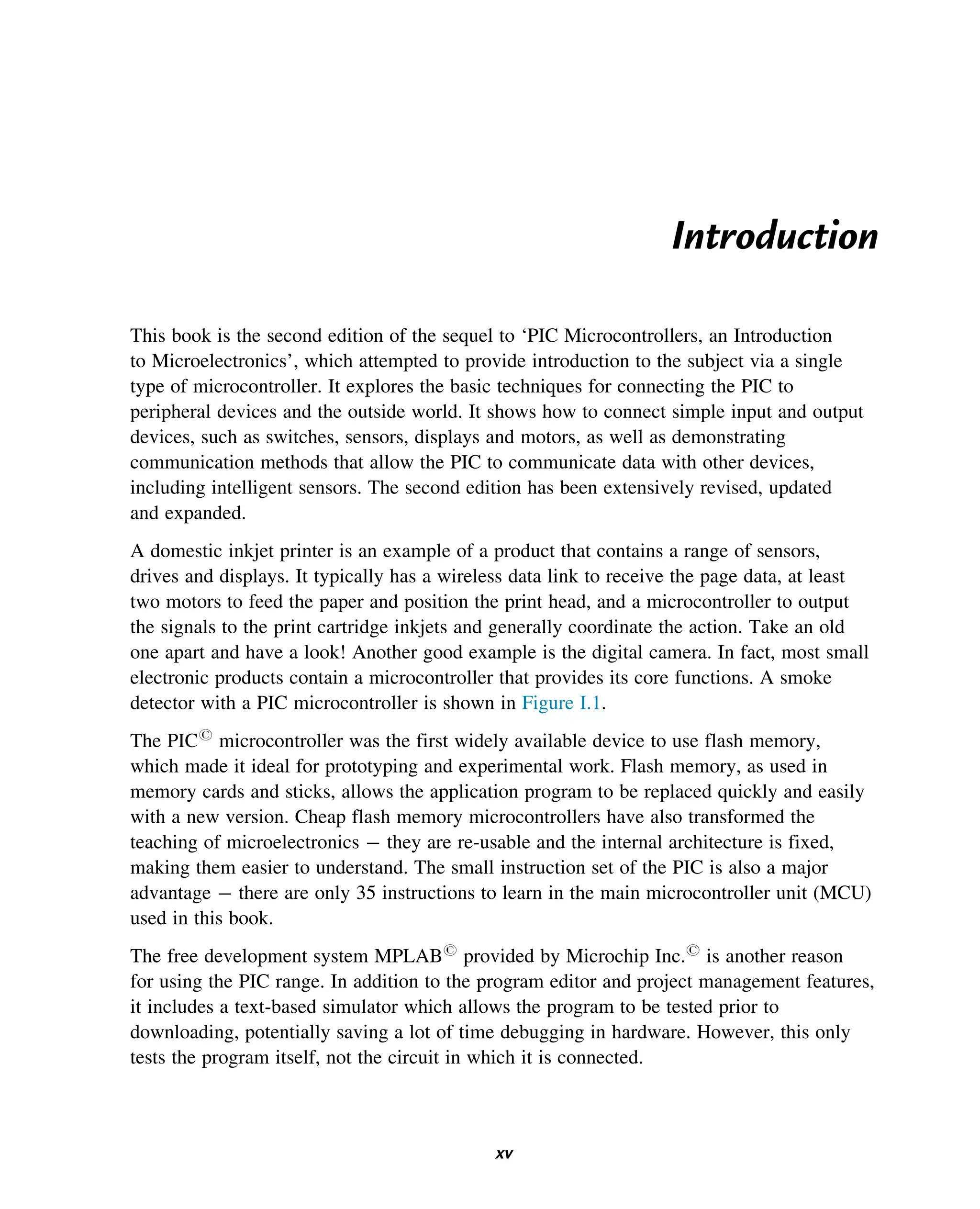
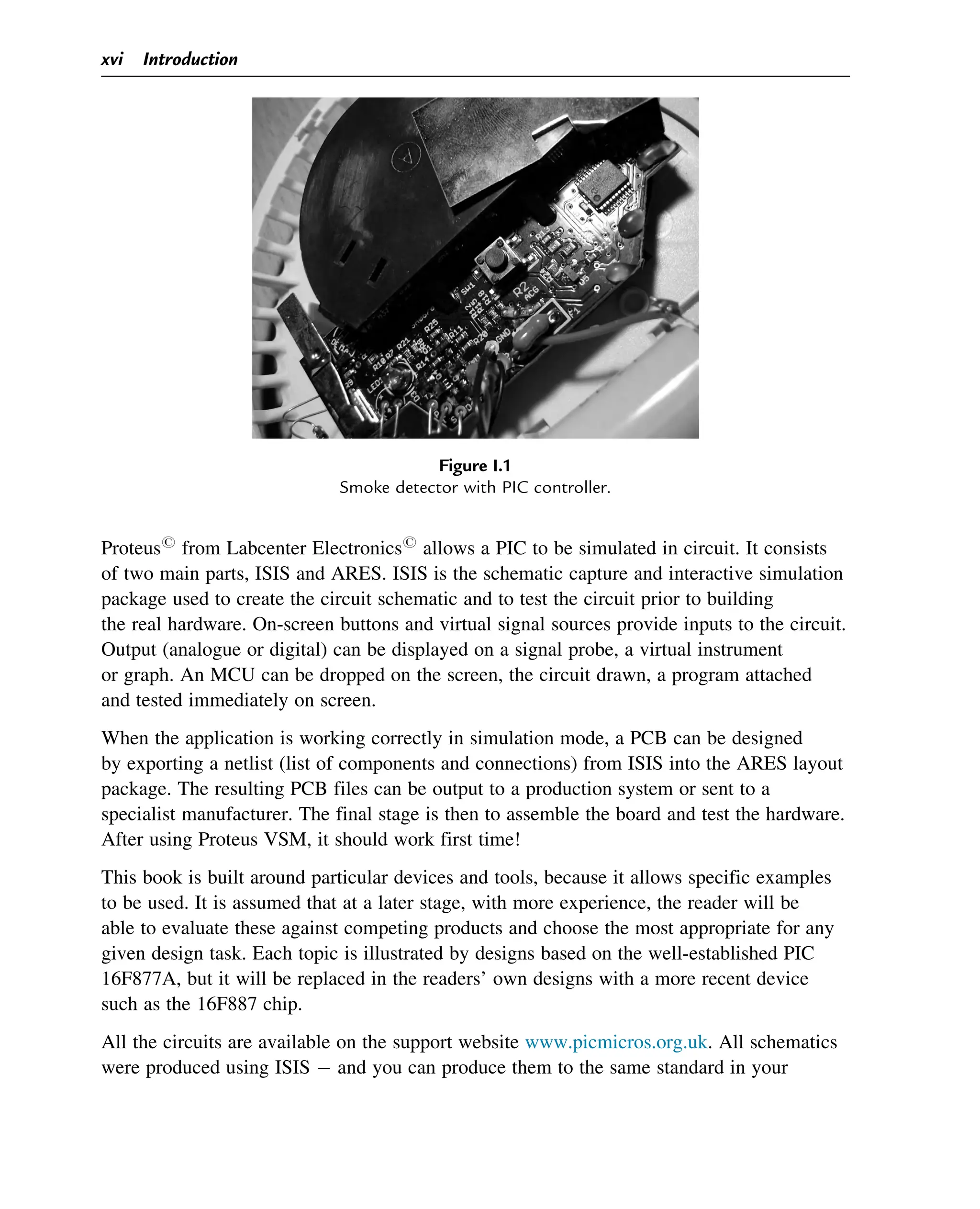
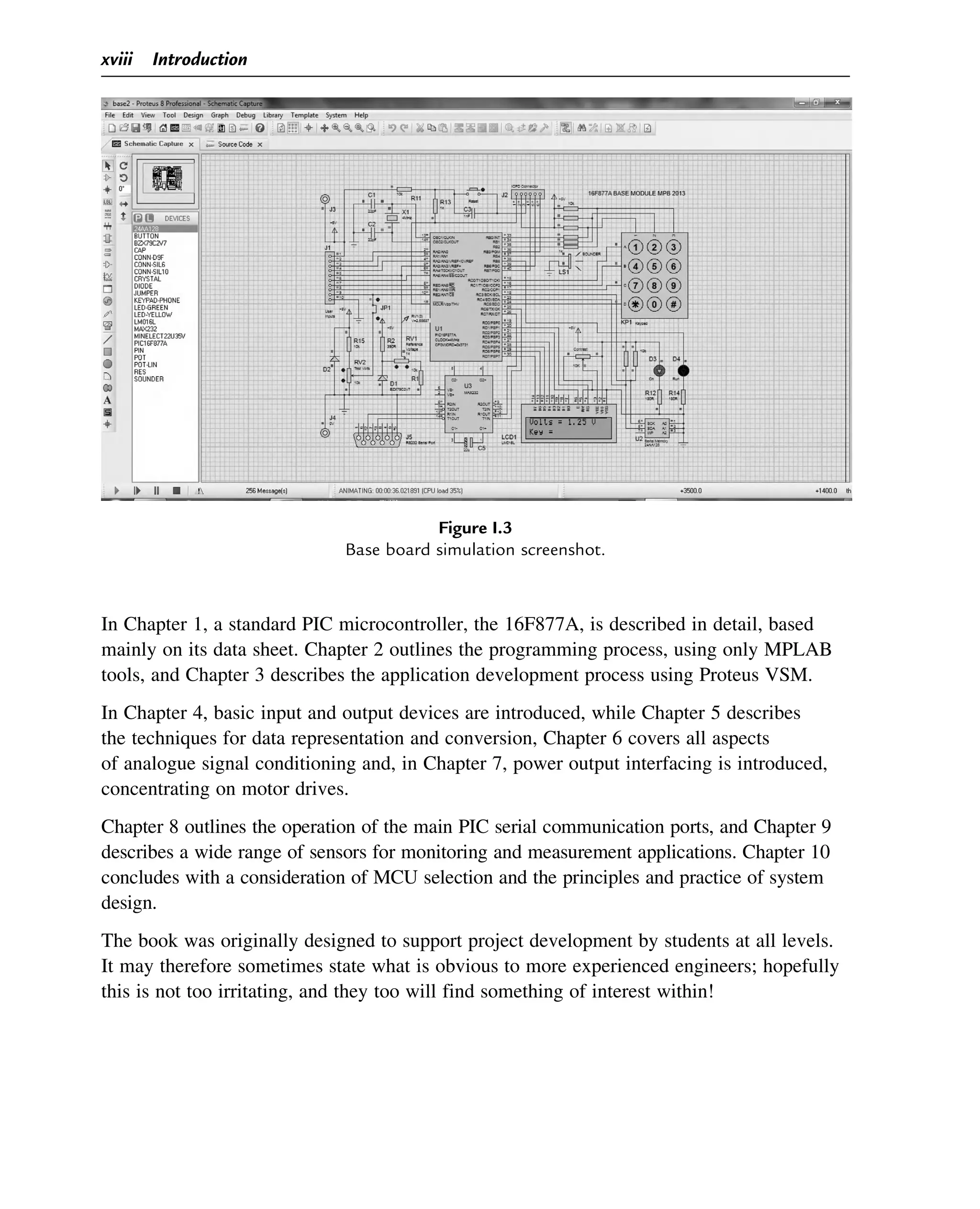

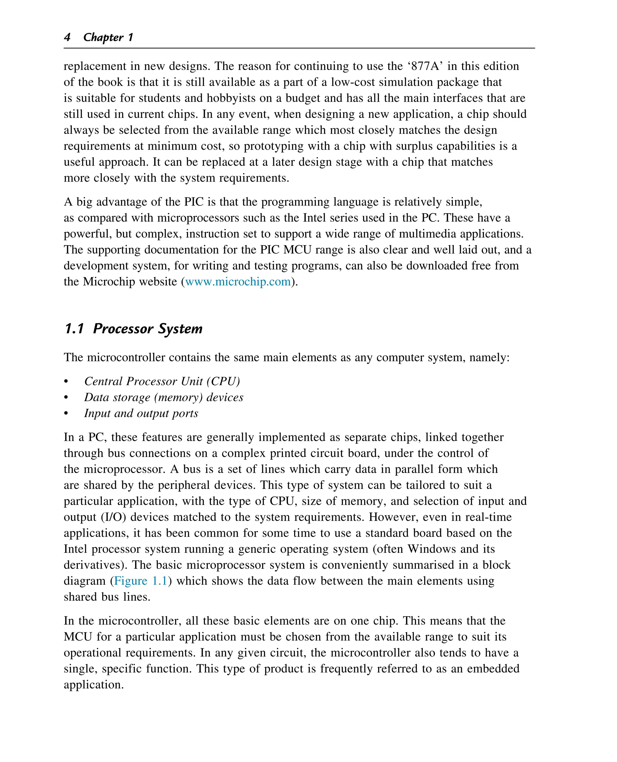
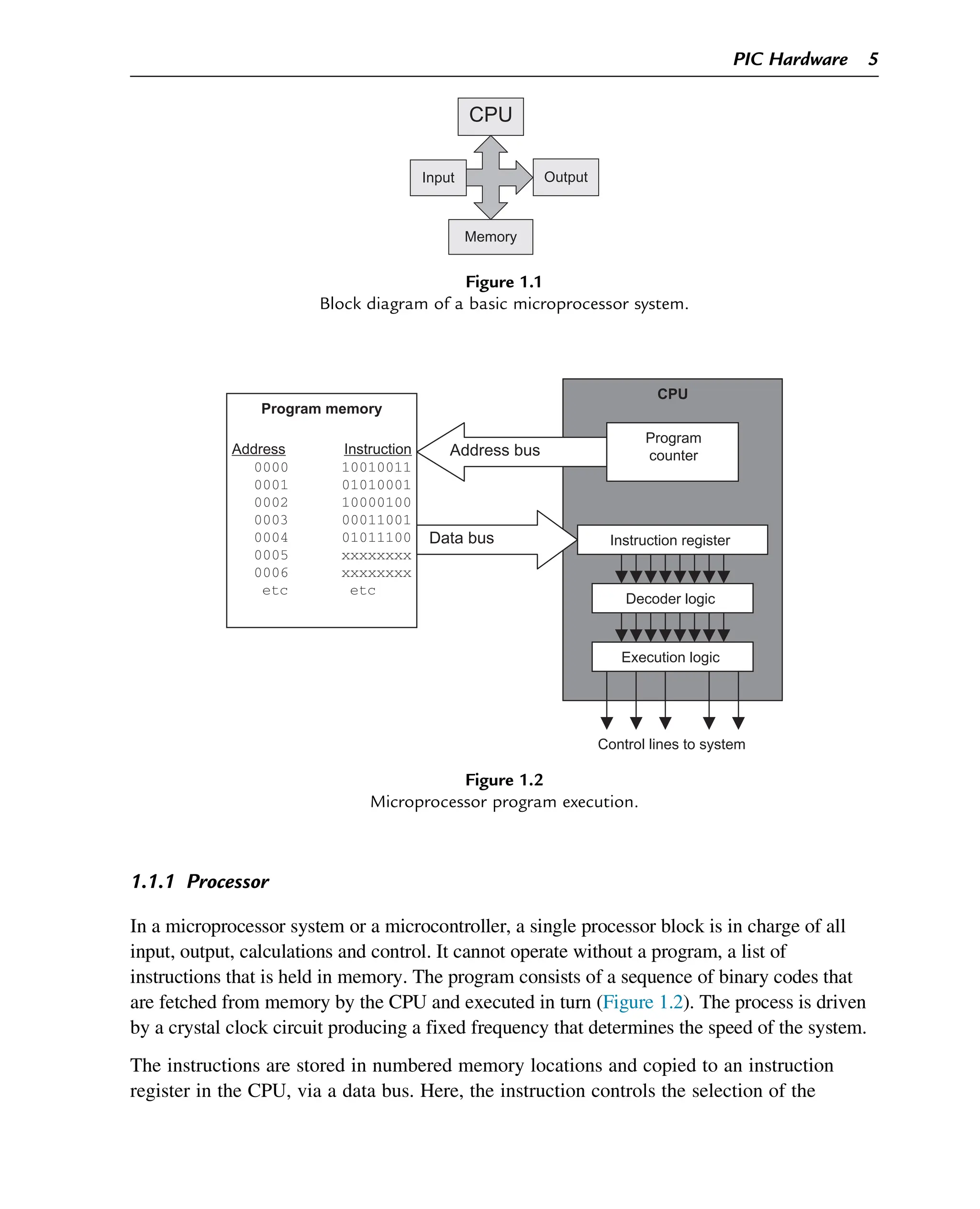
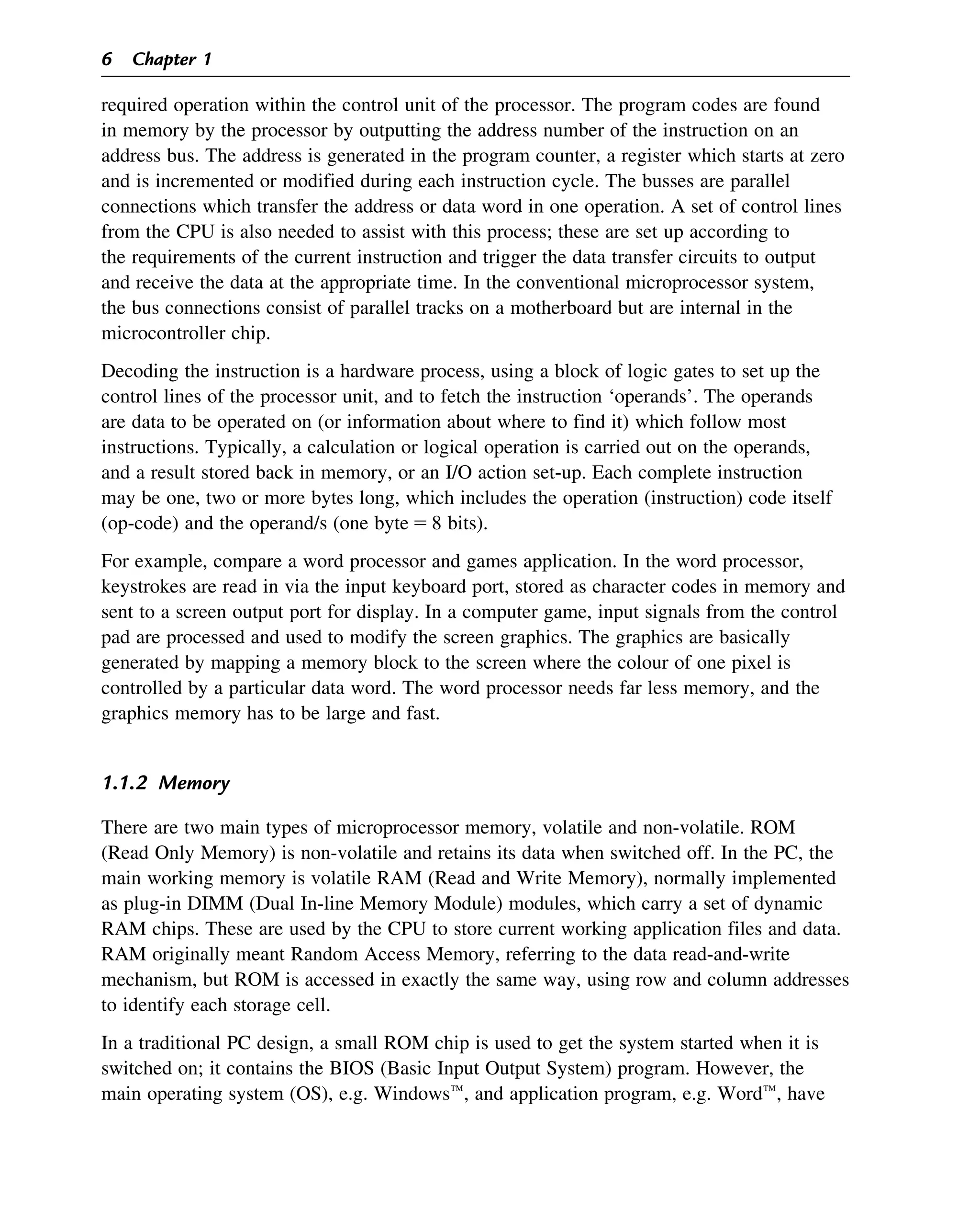
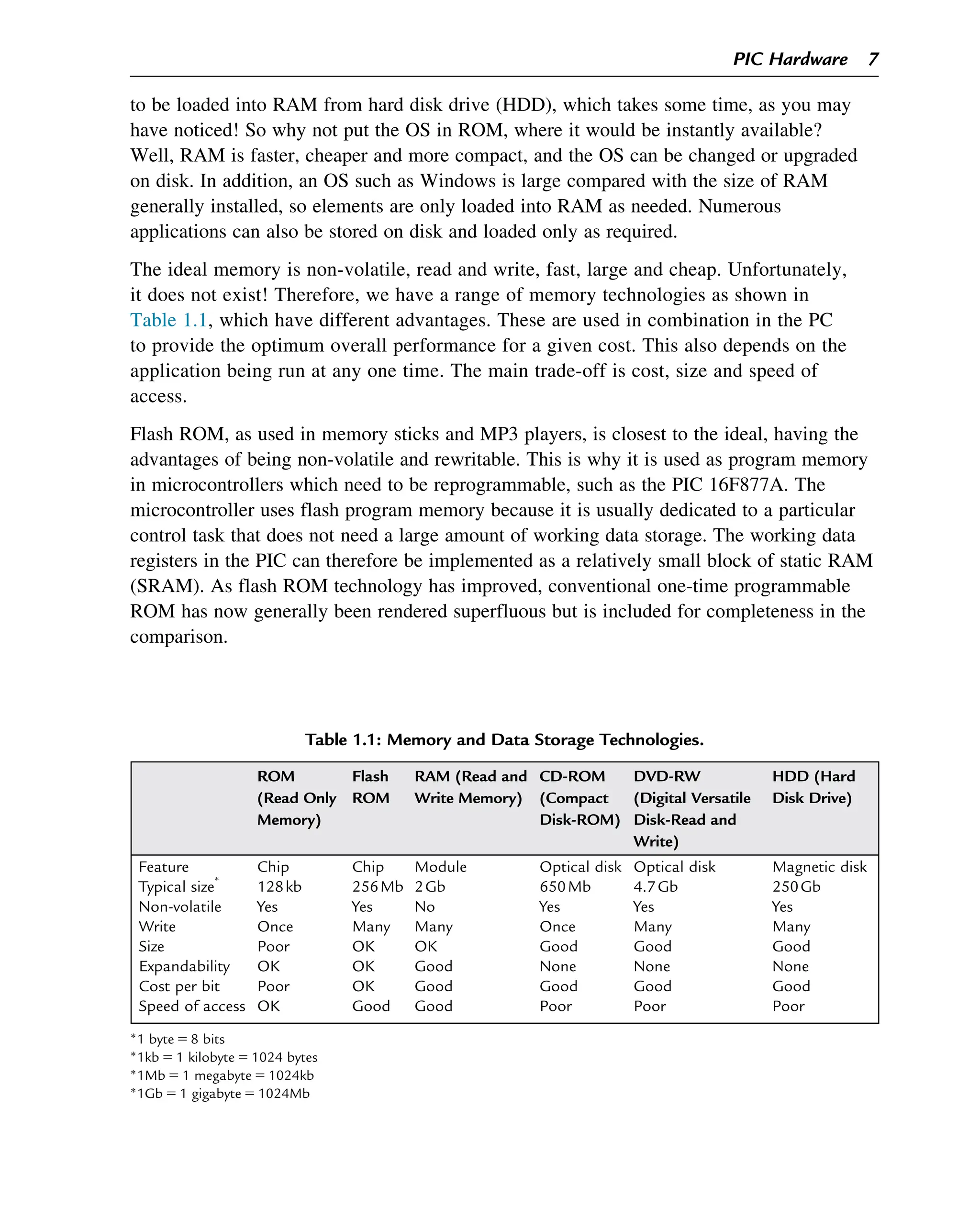
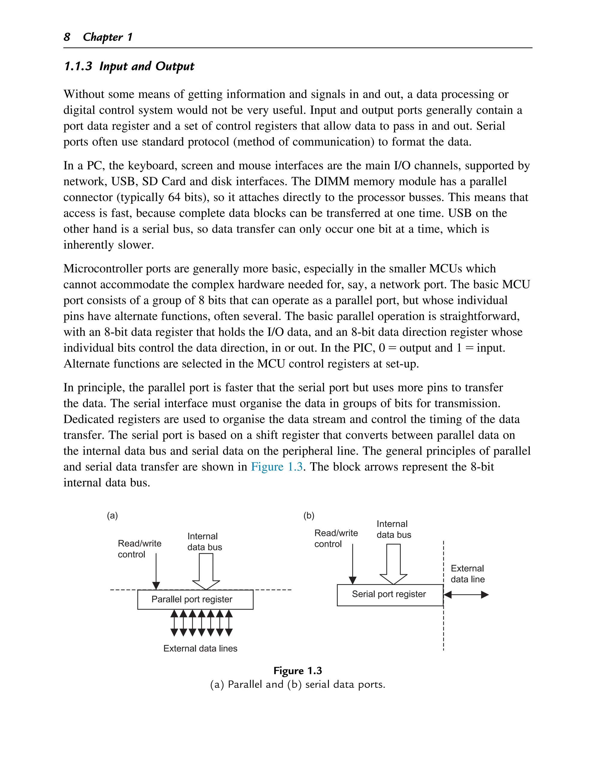
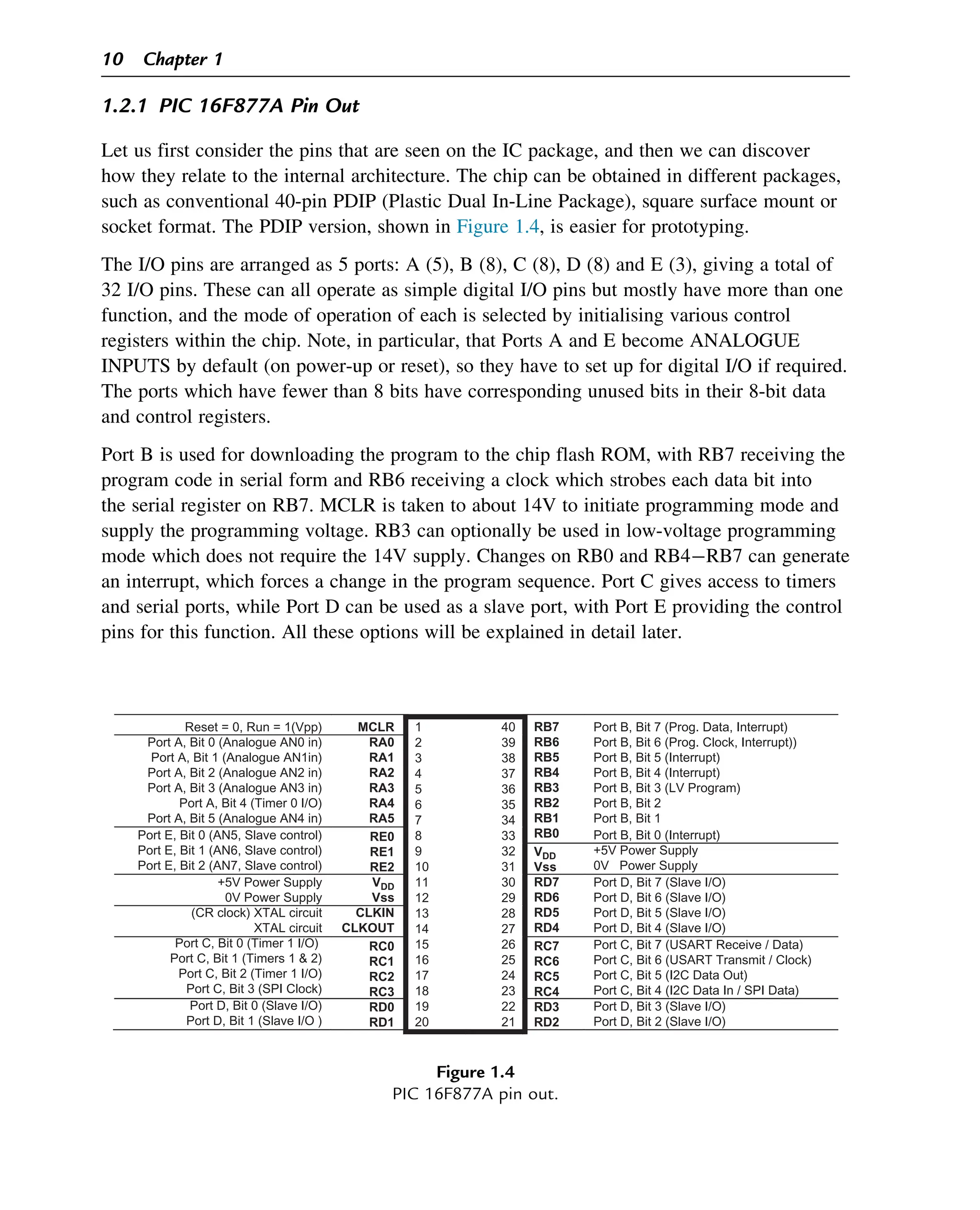
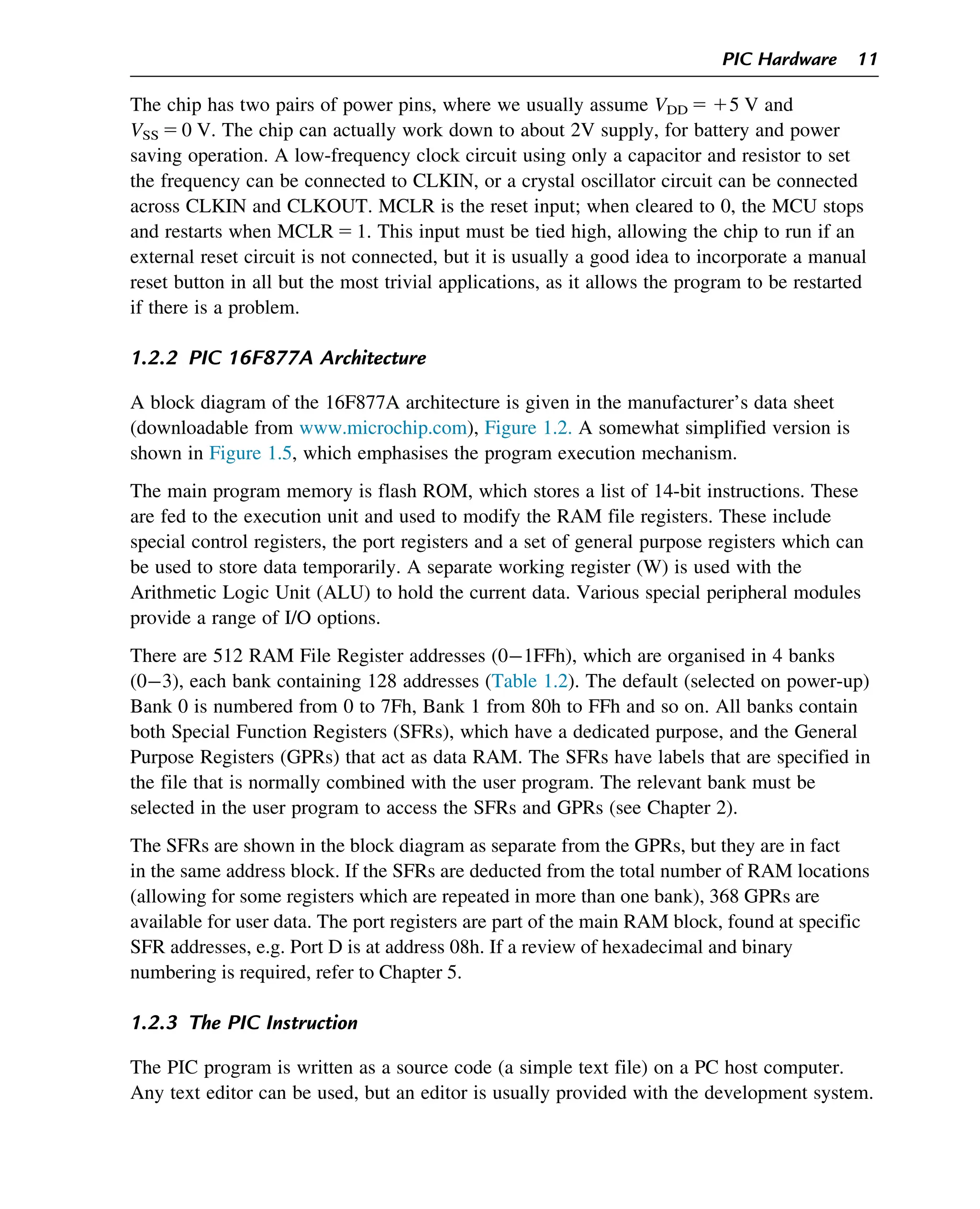
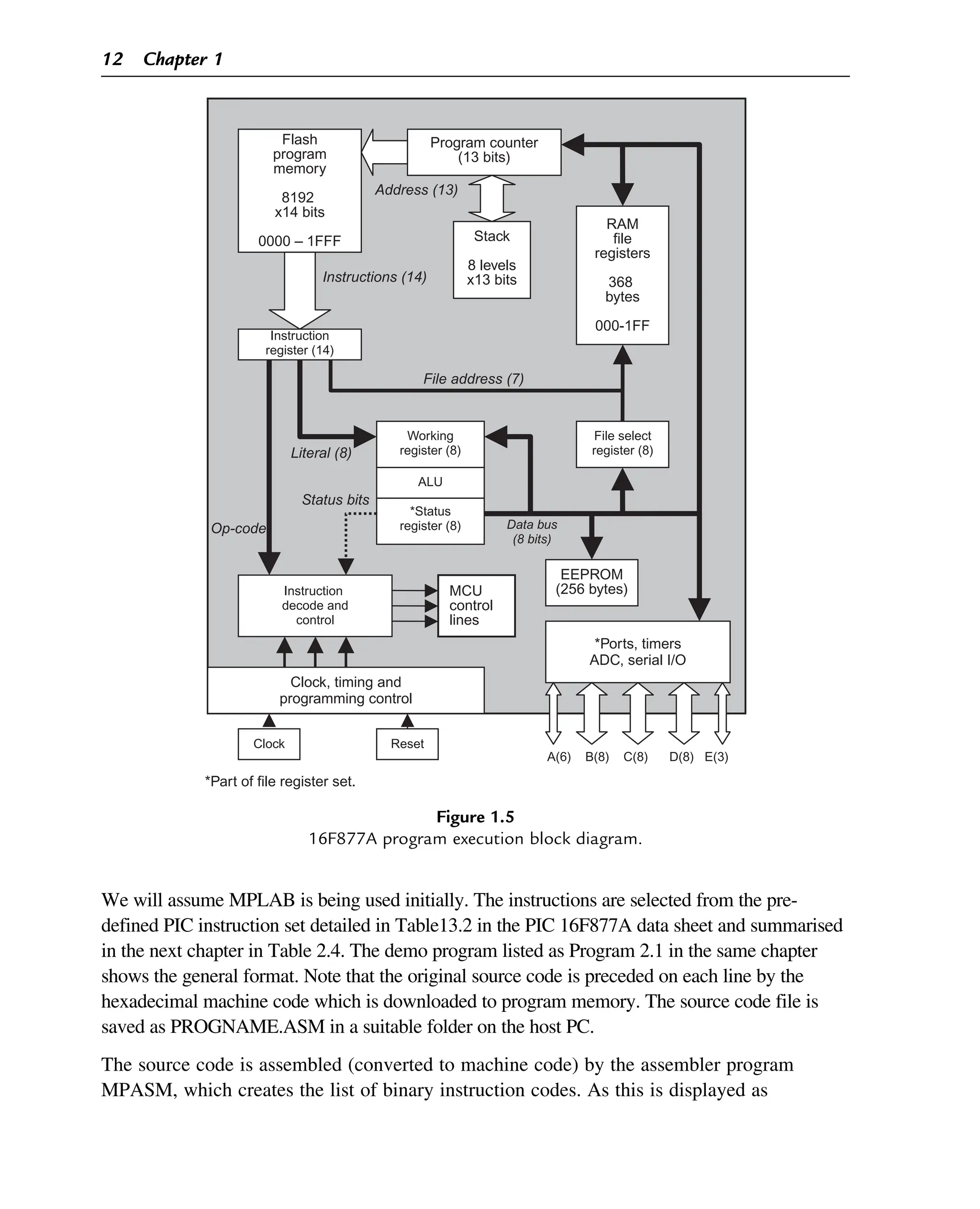
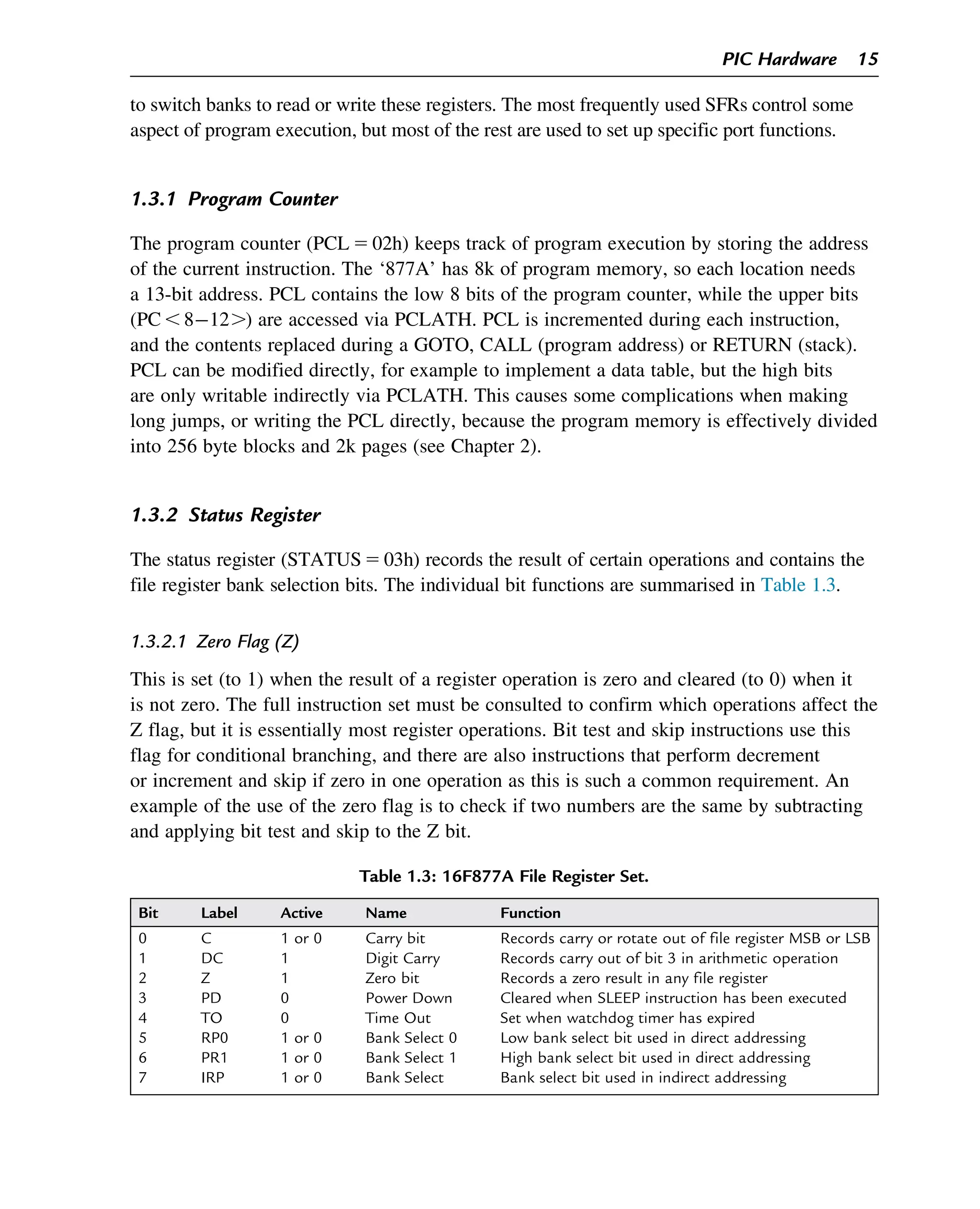
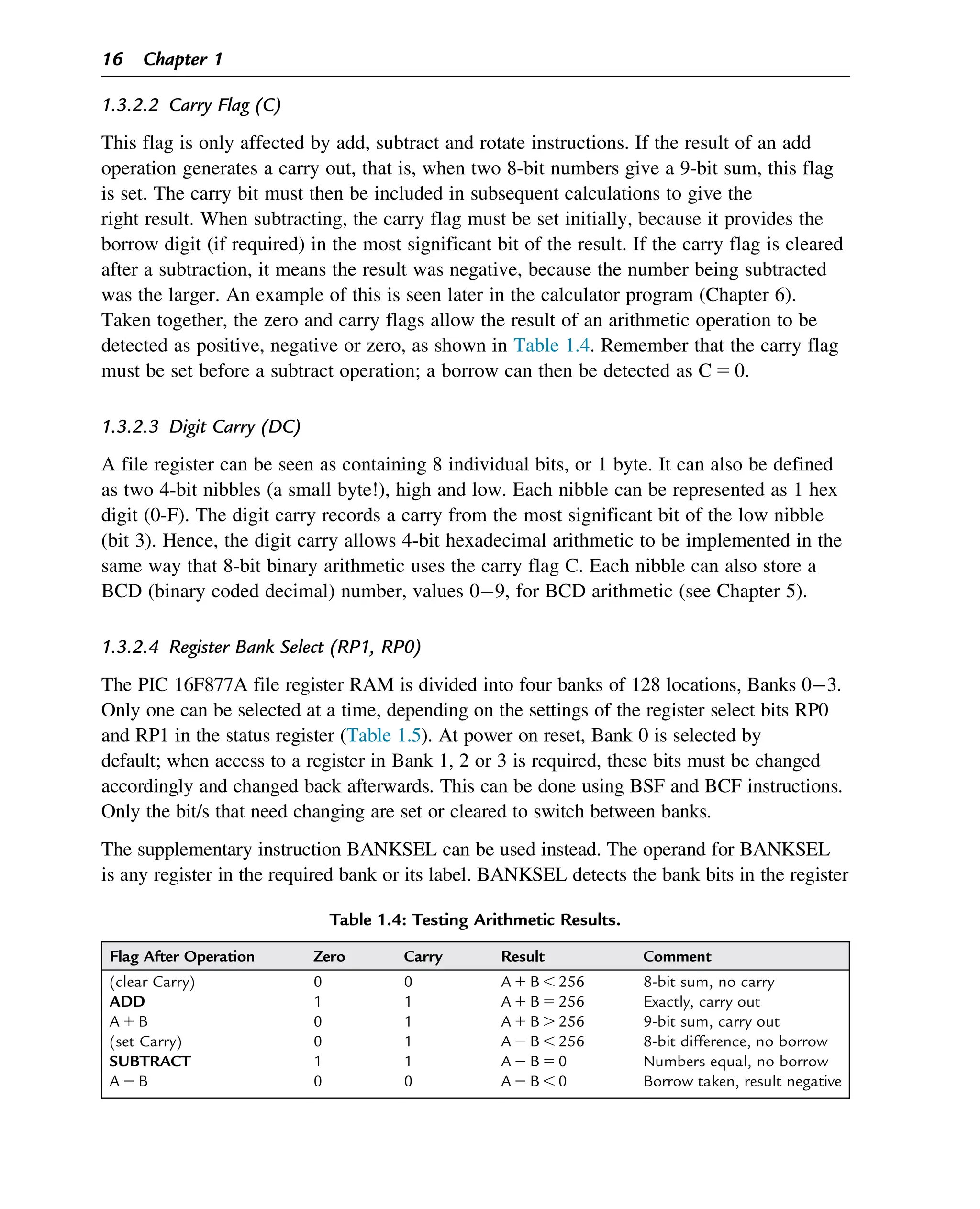
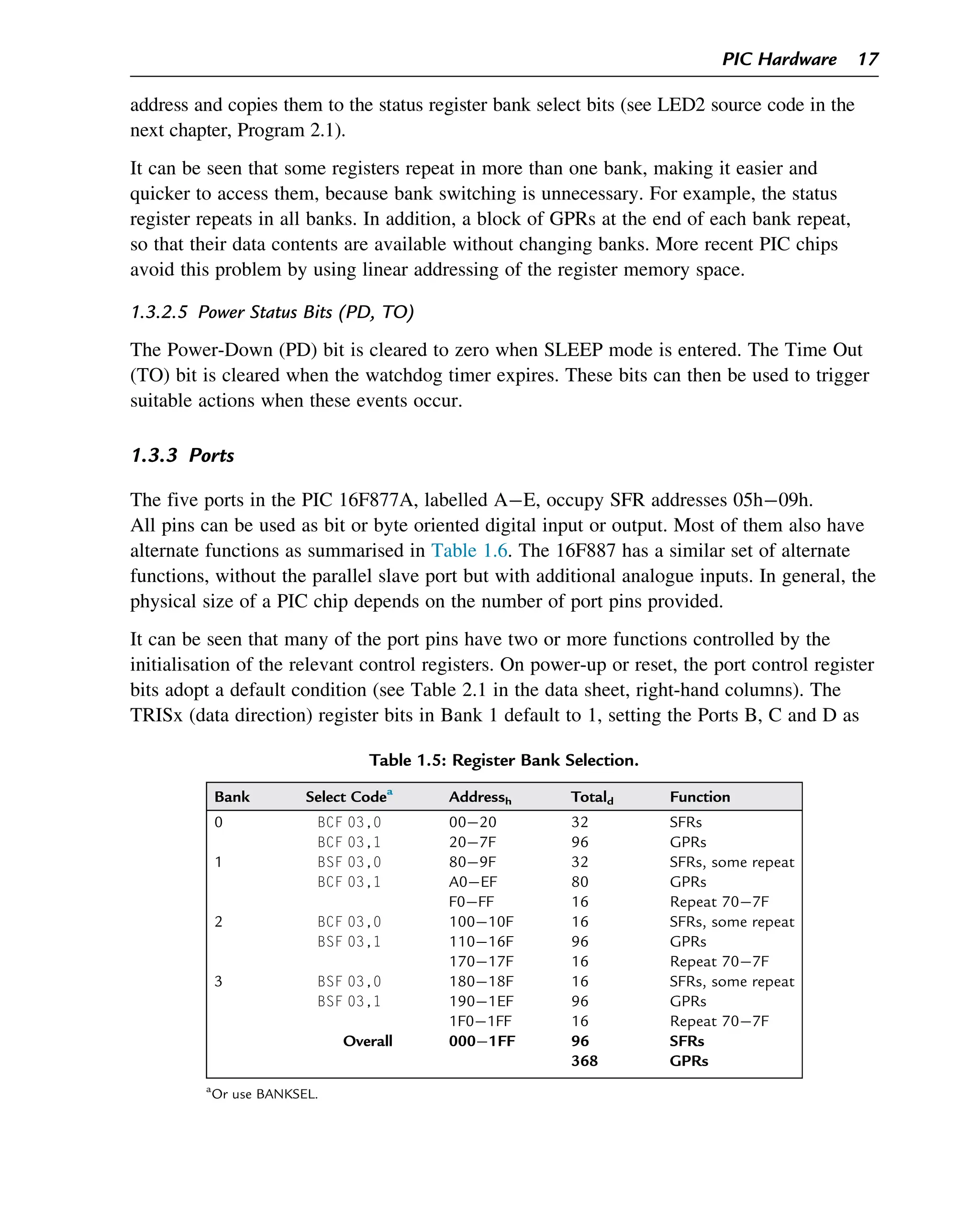
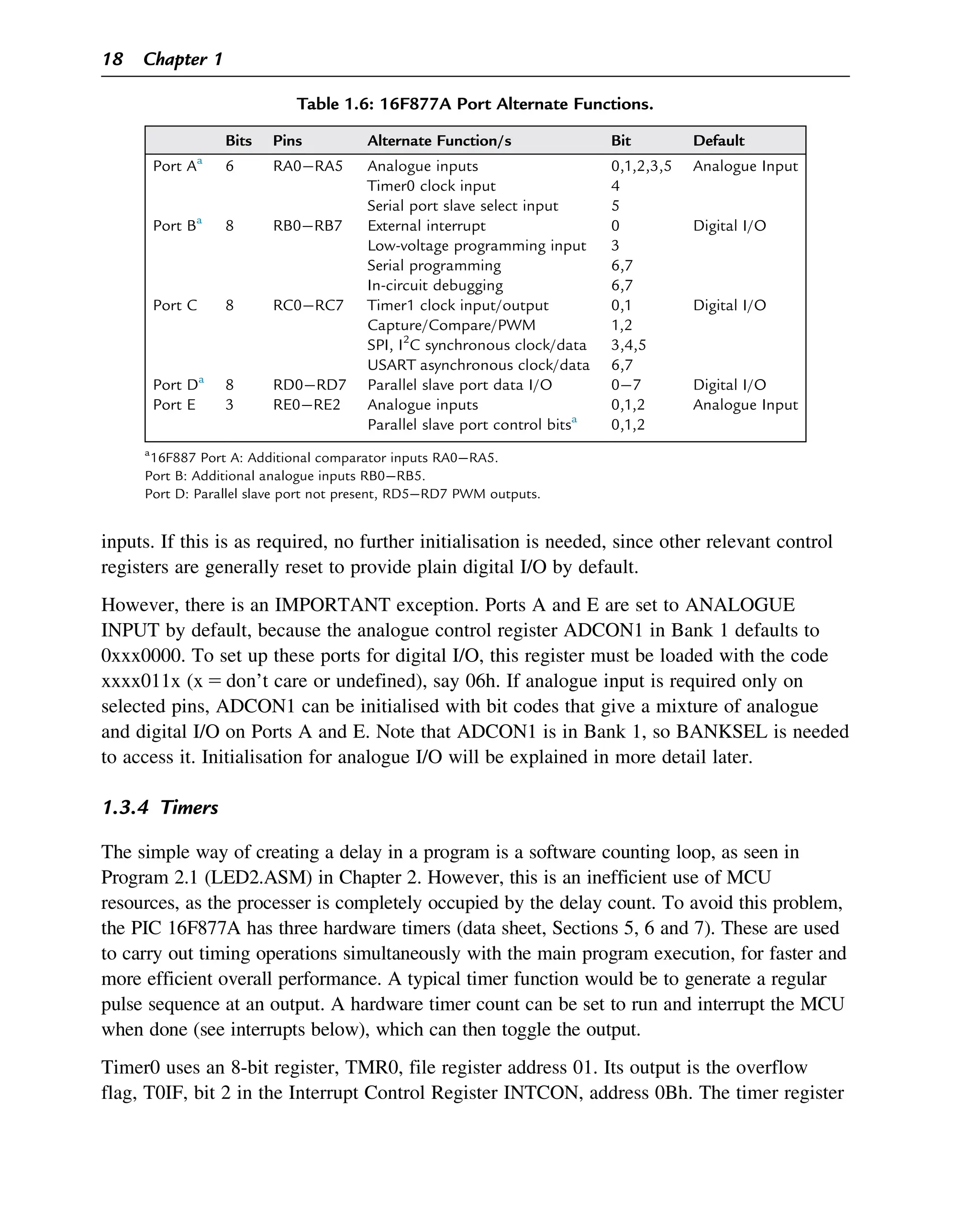
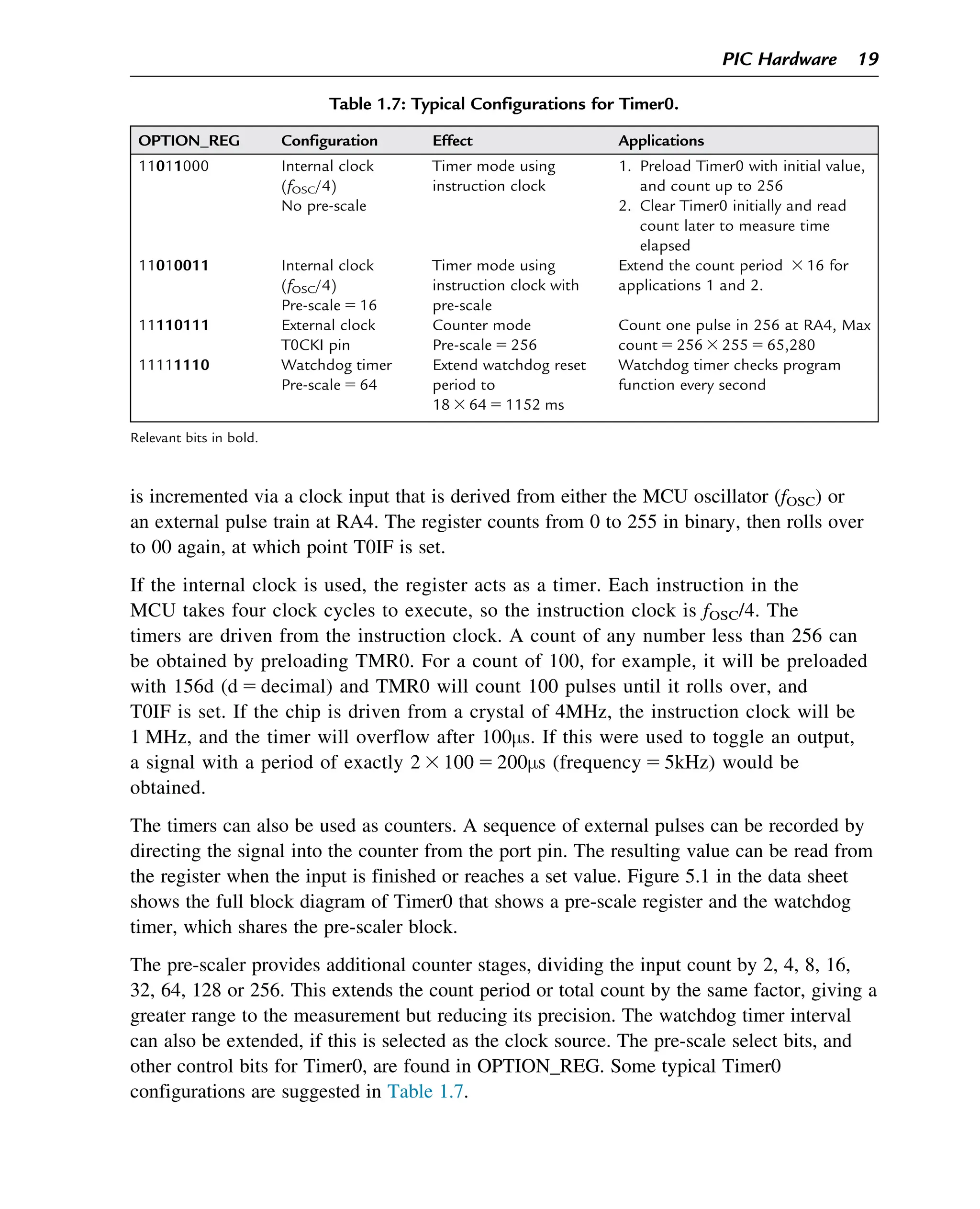
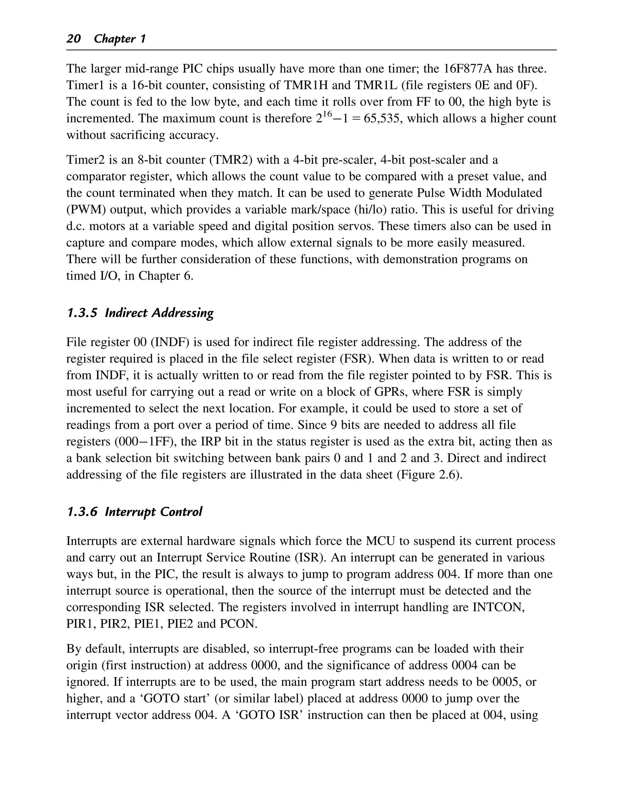
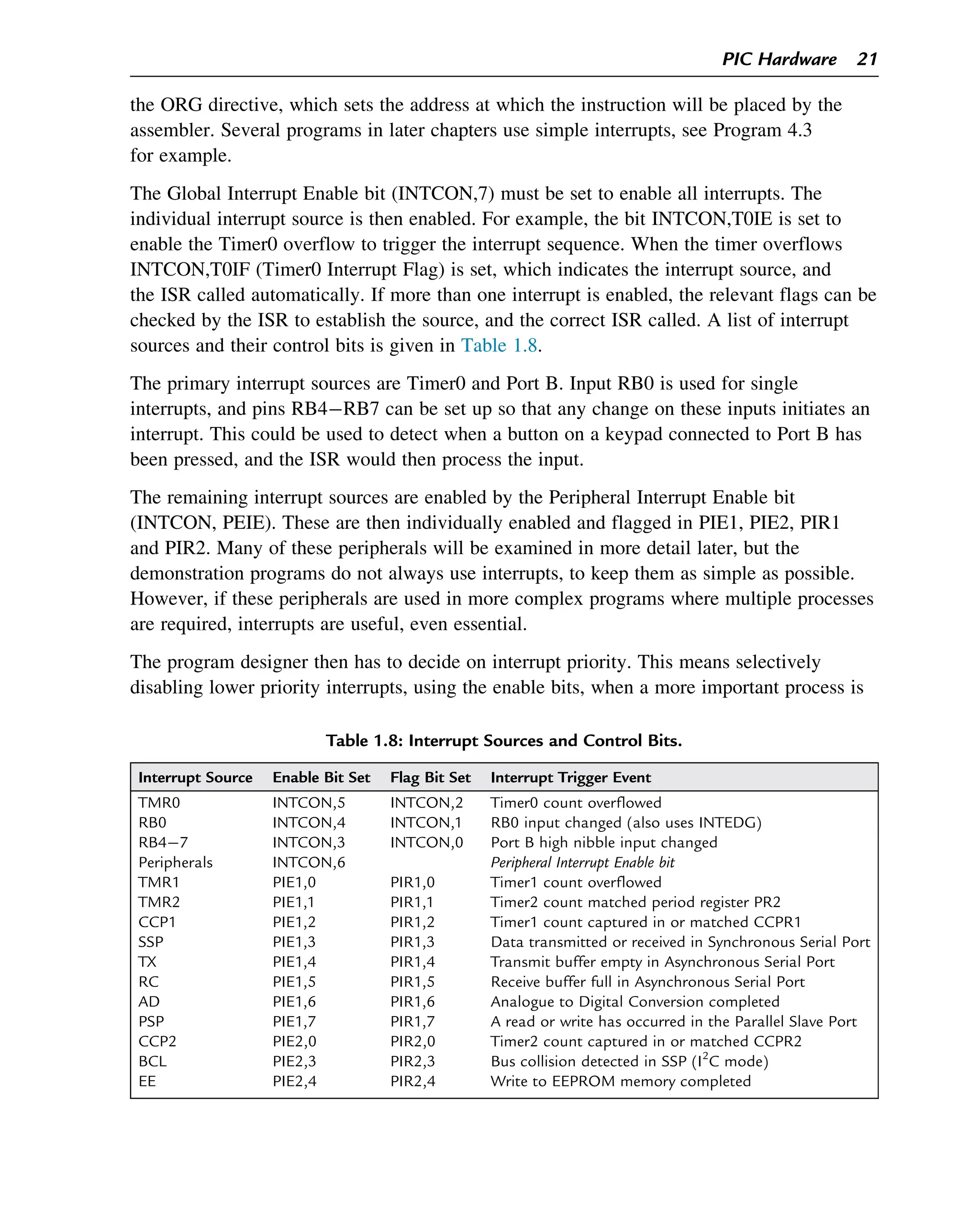

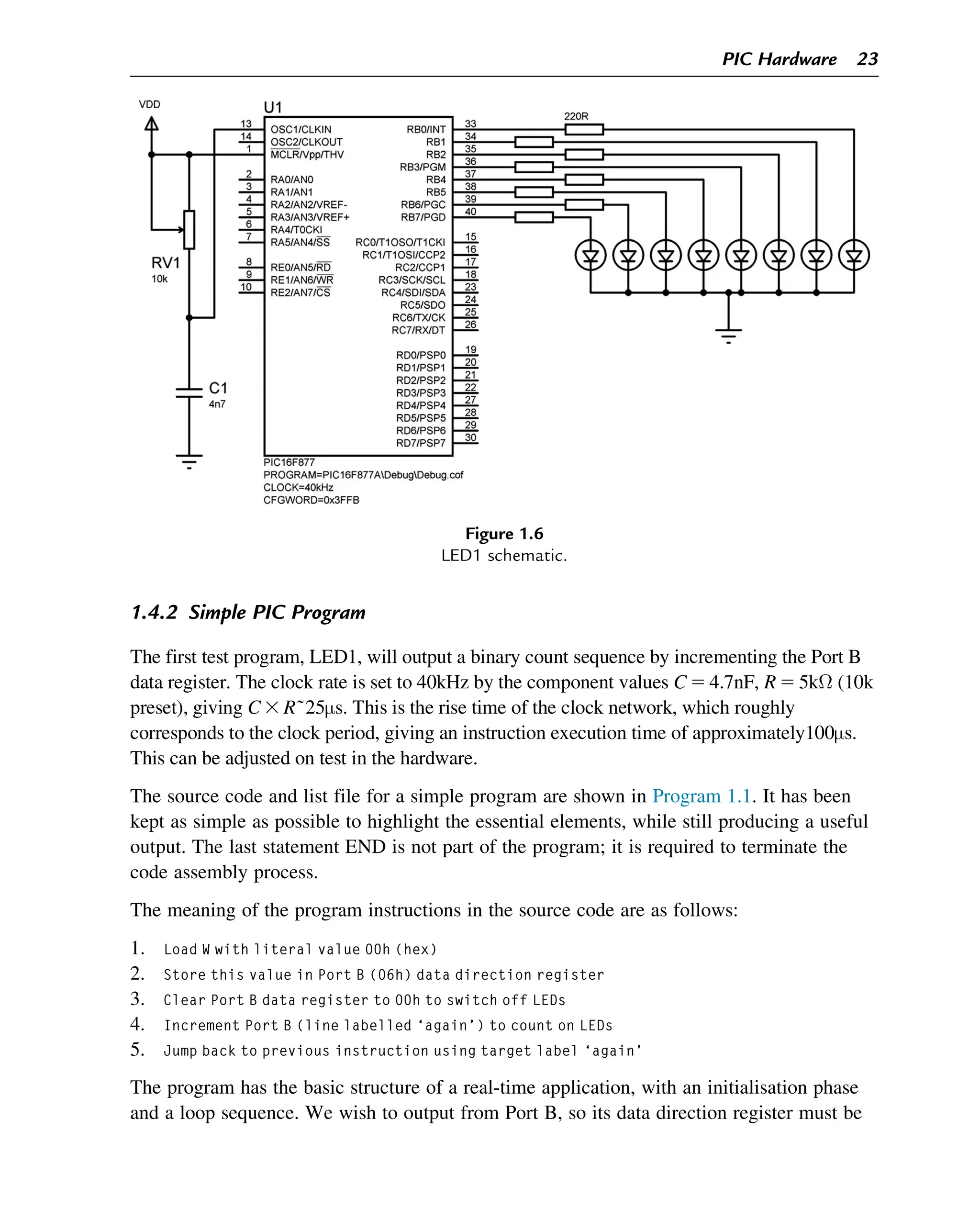
![(a)
(b)
MPASM 5.46 LED1.ASM 9-18-2012 9:11:12 PAGE 1
LOC OBJECT CODE LINE SOURCE TEXT
VALUE
0000 3000 00001 MOVLW 00
Warning[224]: Use of this instruction is not recommended.
0001 0066 00002 TRIS 06
0002 0186 00003 CLRF 06
Message[305]: Using default destination of 1 (file).
0003 0A86 00004 again INCF 06
0004 2803 00005 GOTO again
00006 END
SYMBOL TABLE
LABEL VALUE
__16F877A 00000001
again 00000003
MEMORY USAGE MAP ('X' = Used, '-' = Unused)
0000 : XXXXX----------- ---------------- ----------------
All other memory blocks unused.
Program Memory Words Used: 5
Program Memory Words Free: 8187
Errors : 0
Warnings : 1 reported, 0 suppressed
Messages : 1 reported, 0 suppressed
MOVLW 00
TRIS 06
CLRF 06
again INCF 06
GOTO again
END
Program 1.1
LED1 application files: (a) source code LED1.ASM and (b) list file LED1.LST.
24 Chapter 1](https://image.slidesharecdn.com/43161-250408053121-249d8db2/75/Interfacing-PIC-Microcontrollers-2nd-Edition-Martin-Bates-35-2048.jpg)

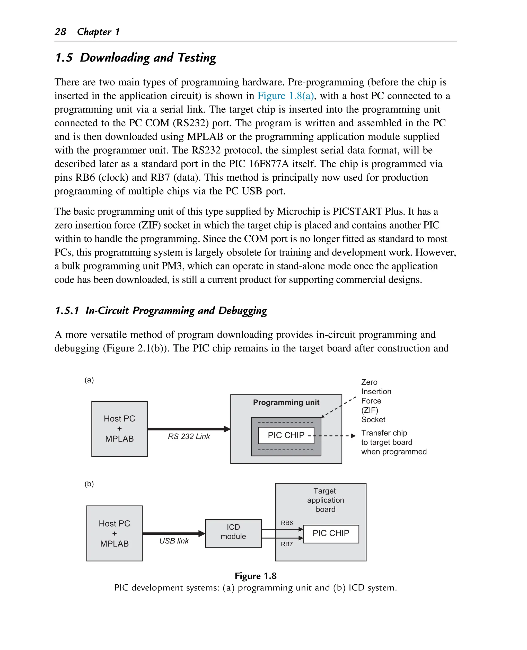
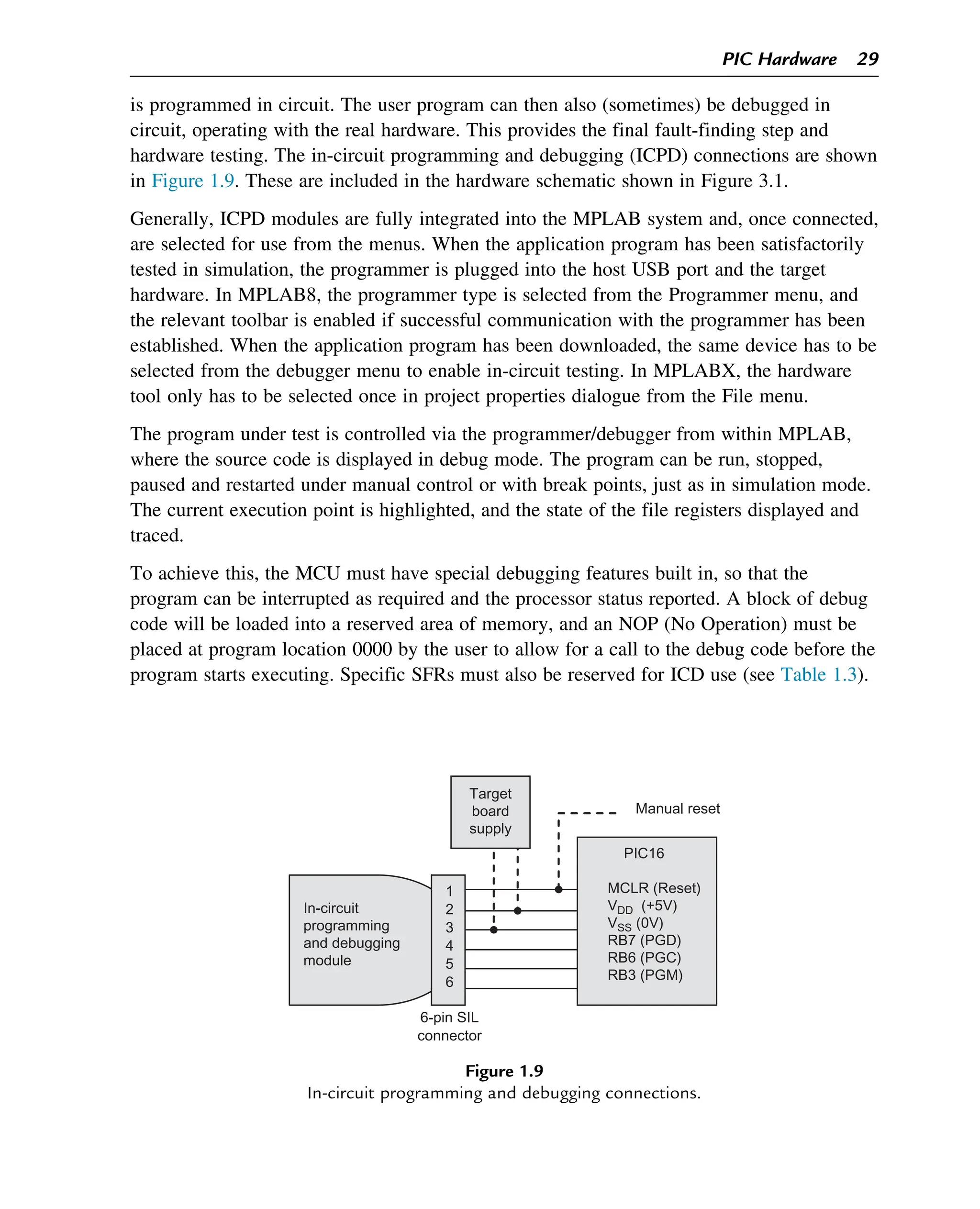

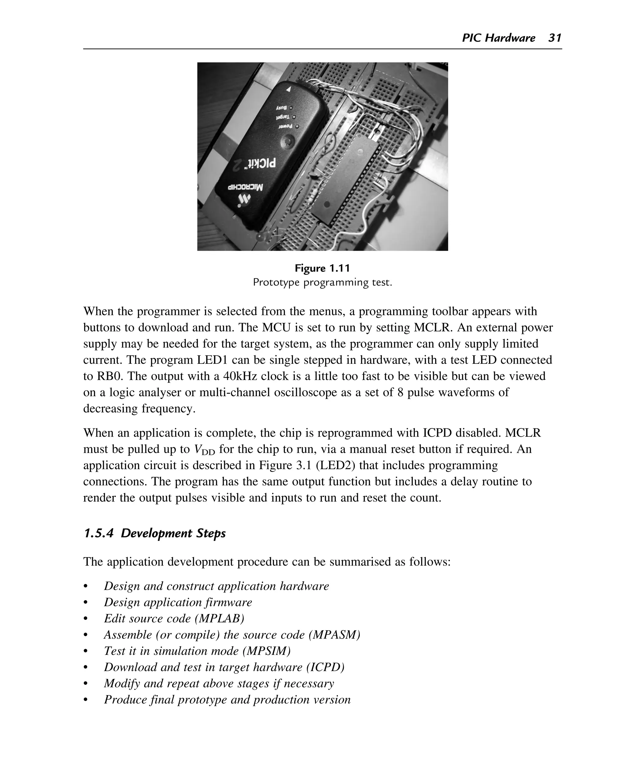
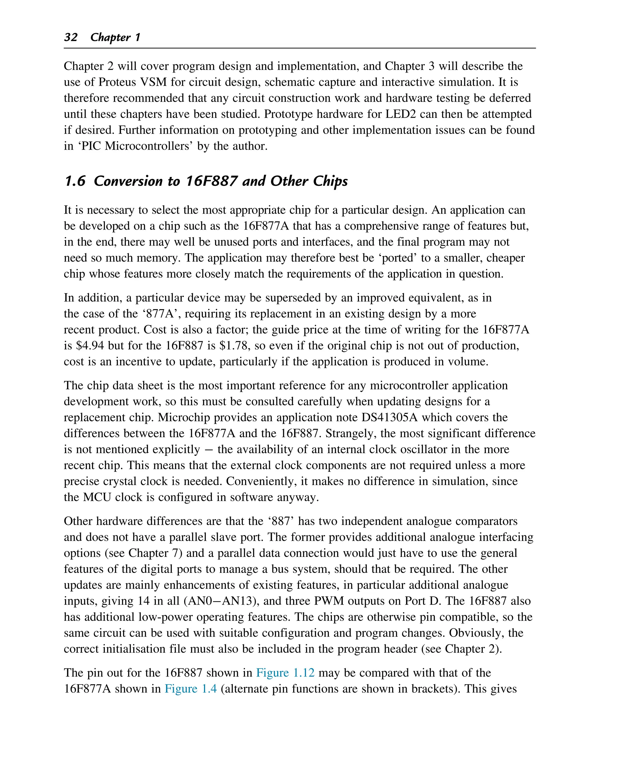
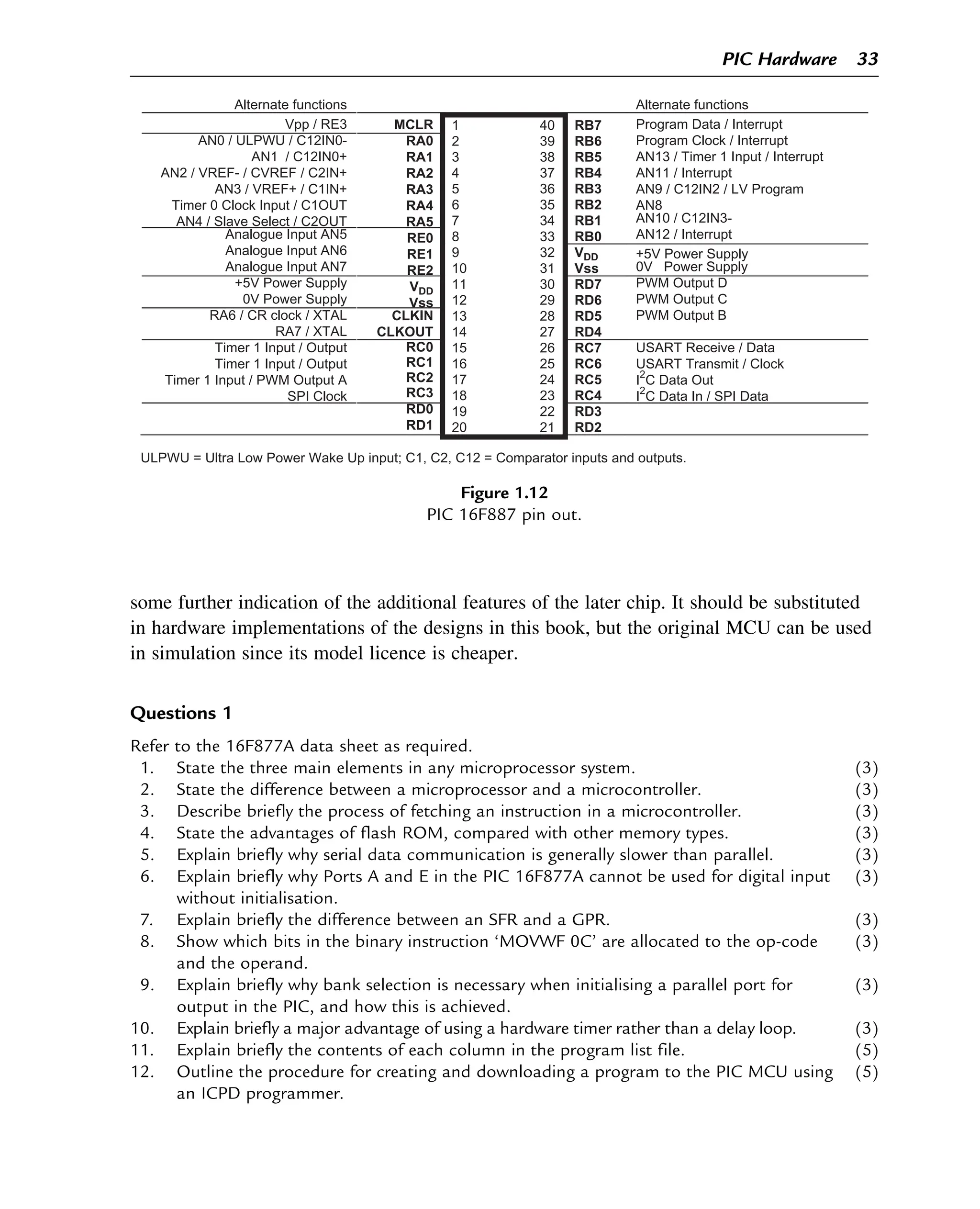


![great on the composition, nor would it be drove every where equal:
to prevent which, observe the following rule; that for those rockets,
that are rammed over a piercer, let the ladle[5]
hold as much
composition as when drove, will raise the drift one half the interior
diameter of the case, and for those drove solid to contain as much as
will raise it half the exterior diameter of the case: ladles are generally
made to go easy in the case, and the length of the scoop about one
and a half of its own diameter.
The charge of rockets must always be drove one diameter above
the piercer, and on it must be rammed one third of a diameter of clay,
through the middle of which bore a small hole to the composition, in
order that, when the charge is burnt to the top, it may communicate
its fire, through the hole, to the stars in the head: great care must
always be taken, to strike with the mallet, and with an equal force,
the same number of strokes to each ladle-ful of charge; otherwise
the rockets will not rise with an uniform motion, nor will the
composition burn equal and regular; for which reason they cannot
carry a proper tail, for it will break before the rocket has got half way
up; instead of reaching from the ground to the top, where the rocket
breaks and disperses the stars, rains, or whatever is contained in the
head. When you are ramming, keep the drift constantly turning or
moving; and when you use the hollow rammers, knock out of them
the composition now and then, or the piercer will split them: to a
rocket of four ounces, give to each ladle-ful of charge sixteen
strokes: to a rocket of eight ounces twenty-one strokes: to a rocket
of one pound, twenty eight: to a two pounder, thirty-six: to a four
pounder forty-two: and to a six pounder fifty strokes; but rockets of a
larger sort cannot be drove well by hand, but must be rammed with a
machine made in the same manner as those for driving piles, which
are so very common to be seen, that I shall here omit giving a
description of them.
The method of ramming of wheel cases, or any other sort, in
which the charge is drove solid, is much the same as sky rockets; for
the same proportion may be observed in the ladle, and the same
number of strokes given, according to their diameters, all cases being](https://image.slidesharecdn.com/43161-250408053121-249d8db2/75/Interfacing-PIC-Microcontrollers-2nd-Edition-Martin-Bates-53-2048.jpg)
![distinguished by their diameters; in this manner, a case whose bore is
equal to a rocket of four ounces is called a four ounce case, and that
which is equal to an eight ounce rocket an eight ounce case, and so
on, according to the different rockets.
Having taught the method of ramming cases in moulds; we shall
here say something concerning those filled without moulds, which
method, for strong pasted cases, will do extremely well, and save the
expence of making so many moulds. The reader must here observe,
when he fills any sort of cases, to place the mould on a perpendicular
block of wood, and not on any place that is hollow, for we have found
by experience, that when cases were rammed on driving benches,
which were formerly used, the works frequently miscarried, on
account of the hollow resistance of the benches, which often jarred
and loosened the charge in the cases; but this accident has never
happened since the driving blocks[6]
have been used.
When cases are to be filled without moulds, proceed thus; have
some nipples made of brass or iron, of several sorts and sizes, in
proportion to the cases, and to screw or six in the top of the driving
block; when you have fixed in a nipple, make, at about one inch and
a half from it, a square hole in the block, six inches deep and one
inch diameter; then have a piece of wood, six inches longer than the
case intended to be filled and two inches square; on one side of it cut
a groove almost the length of the case, whose breadth and depth
must be sufficient to cover near half the case; then cut the other end
to fit the hole in the block, but take care to cut it so that the groove
may be of a proper distance from the nipple: this half mould being
made and fixed tight in the block, cut, in another piece of wood
nearly of the same length as the case, a groove of the same
dimensions as that in the fixed piece; then put the case on the
nipple, and with a cord tie it and the two half moulds together, and
your case will be ready for filling.
The dimensions of the above described half moulds, are
proportionable for cases of eight ounces; but notice must be taken,
that they differ in size in proportion to the cases.](https://image.slidesharecdn.com/43161-250408053121-249d8db2/75/Interfacing-PIC-Microcontrollers-2nd-Edition-Martin-Bates-54-2048.jpg)