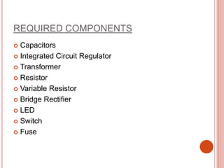
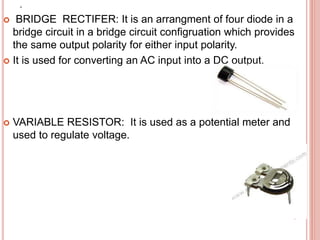
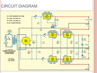
ELECTRONIC DEVICES PROJECT
TRIPLE POWER SUPPLY
INTRODUCTION
We are going through a period of micro-electronic
revolution. so we need to reduce the size of the
system that are using for different purposes. Power
supply is the heart of all electronic equipments. If
more than two voltages are available in a single
power supply it is more useful in laboratory
experiments. So it is convenient to use a power
supply which could drive both linear and parallel
ICs. In this project we are introducing ‘TRIPLE
POWER SUPPLY'.
REQUIRED COMPONENTS
 Capacitors
 Integrated Circuit Regulator
 Transformer
 Resistor
 Variable Resistor
 Bridge Rectifier
 LED
 Switch
 Fuse
 RESISTOR:
It is a device which resist the flow of current. It has two
terminals across which electricity can pass,and it is desiged
to drop the voltage of the current as it flows from one
terminal to other.
CAPACITOR: A capacitor is a passive two-terminal electrical
component used to store energy in an electric field. It allows
ac current and blocks dc current.
.
 LED:Light emitting diodes are a semiconducting device.
LEDs are made on single crystal silicon carbide
substance. It emits light when current passes through it.
 It converts electrical energy into light energy.
 IC REGULATOR: It is used to convert high voltage to
certain amount of voltage.
.
 BRIDGE RECTIFER: It is an arrangment of four diode in a
bridge circuit in a bridge circuit configruation which provides
the same output polarity for either input polarity.
 It is used for converting an AC input into a DC output.
 VARIABLE RESISTOR: It is used as a potential meter and
used to regulate voltage.
.
 TRASFORMER: It is devices which changes the current and the
voltage of the signal, keeping the power level same.
 Transformer transfer energy from one coil to another through
magnetic flux leakage.
 SWITCH: It is a device which is used for making circuit working
in off and on positions.
 FUSE: It is a device which is useful during short circuit.
CIRCUIT DIAGRAM
WORKING PRINCIPLE:
 CIRCUIT DISCRIPTION:
Above figure shows the circuit diagram of triple power
supply. Transformer X1 steps down the main power to
deliver the secondary output of 18-0-18V. The transformer
output is rectified by full wave bridge rectifier BR1, filtered by
capacitors C1, C2, C3, C7 and C8 and regulated by IC1 to
IC5. Regulator IC1 (LM317) provides variable voltages (1.25
to 20V), while IC2 and IC4 provides +15V and -15V
respectively. The output of IC2 is fed to regulator IC3 (7805),
which provide +5. Similarly output of IC4 is fed to regulator
IC5 (7905), which provide fixed -5V. Capacitor C4 through
C6 and C9 through C11, are used for further filtering of
ripples in positive and negative regulated power supplies.
LED1 glows to indicate that +5V is available while
LED2indicates that -5V is available. Switch S1 is used for
mains ‘ON’/’OFF’. Using switches S2 through S4, any of the
three supplies can independently turn off when not required
in a particular experiment.
ADVANTAGES
 This reduces unnecessary power dissipation and
increases the life reliability of the power supply.
 Since the circuit uses three terminal regulators, only
capacitor are required at input and output.
 These have inbuilt protection circuits including the
thermal shut down protection.
CONCLUSION
In this nano technology world triple power supply
reduces the size and cost. Variable power supply is
used to study the characteristics of devices. Fixed
+5V power supply is used for all digital,
microprocessor and microcontroller experiments.
Dual ±15V power supply is used for op-amp-based
analogue circuit experiments.
Triple power supply

Triple power supply

  • 1.
  • 2.
    INTRODUCTION We are goingthrough a period of micro-electronic revolution. so we need to reduce the size of the system that are using for different purposes. Power supply is the heart of all electronic equipments. If more than two voltages are available in a single power supply it is more useful in laboratory experiments. So it is convenient to use a power supply which could drive both linear and parallel ICs. In this project we are introducing ‘TRIPLE POWER SUPPLY'.
  • 3.
    REQUIRED COMPONENTS  Capacitors Integrated Circuit Regulator  Transformer  Resistor  Variable Resistor  Bridge Rectifier  LED  Switch  Fuse
  • 4.
     RESISTOR: It isa device which resist the flow of current. It has two terminals across which electricity can pass,and it is desiged to drop the voltage of the current as it flows from one terminal to other. CAPACITOR: A capacitor is a passive two-terminal electrical component used to store energy in an electric field. It allows ac current and blocks dc current.
  • 5.
    .  LED:Light emittingdiodes are a semiconducting device. LEDs are made on single crystal silicon carbide substance. It emits light when current passes through it.  It converts electrical energy into light energy.  IC REGULATOR: It is used to convert high voltage to certain amount of voltage.
  • 6.
    .  BRIDGE RECTIFER:It is an arrangment of four diode in a bridge circuit in a bridge circuit configruation which provides the same output polarity for either input polarity.  It is used for converting an AC input into a DC output.  VARIABLE RESISTOR: It is used as a potential meter and used to regulate voltage.
  • 7.
    .  TRASFORMER: Itis devices which changes the current and the voltage of the signal, keeping the power level same.  Transformer transfer energy from one coil to another through magnetic flux leakage.  SWITCH: It is a device which is used for making circuit working in off and on positions.  FUSE: It is a device which is useful during short circuit.
  • 8.
  • 9.
    WORKING PRINCIPLE:  CIRCUITDISCRIPTION: Above figure shows the circuit diagram of triple power supply. Transformer X1 steps down the main power to deliver the secondary output of 18-0-18V. The transformer output is rectified by full wave bridge rectifier BR1, filtered by capacitors C1, C2, C3, C7 and C8 and regulated by IC1 to IC5. Regulator IC1 (LM317) provides variable voltages (1.25 to 20V), while IC2 and IC4 provides +15V and -15V respectively. The output of IC2 is fed to regulator IC3 (7805), which provide +5. Similarly output of IC4 is fed to regulator IC5 (7905), which provide fixed -5V. Capacitor C4 through C6 and C9 through C11, are used for further filtering of ripples in positive and negative regulated power supplies. LED1 glows to indicate that +5V is available while LED2indicates that -5V is available. Switch S1 is used for mains ‘ON’/’OFF’. Using switches S2 through S4, any of the three supplies can independently turn off when not required in a particular experiment.
  • 10.
    ADVANTAGES  This reducesunnecessary power dissipation and increases the life reliability of the power supply.  Since the circuit uses three terminal regulators, only capacitor are required at input and output.  These have inbuilt protection circuits including the thermal shut down protection.
  • 11.
    CONCLUSION In this nanotechnology world triple power supply reduces the size and cost. Variable power supply is used to study the characteristics of devices. Fixed +5V power supply is used for all digital, microprocessor and microcontroller experiments. Dual ±15V power supply is used for op-amp-based analogue circuit experiments.