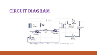
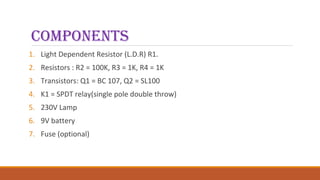
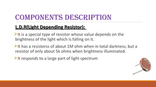
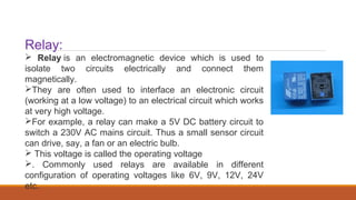
Street Light ControLLer
CirCuit
TEAM MEMBERS: INTERNAL GUIDE:
G SWATHI-127B1A0413 ASST PROF. REVATHI MADAM
E SUDHA RANI-127B1A0423
G SHRUTHI-127B1A0428
introduCtion
Street lights are the major requirement in today’s life of
transportation for safety purposes and avoiding accidents
during night.
Despite that in today’s busy life no one bothers to switch
it off/on when not required.
The project introduced here gives solution to this by
eliminating manpower and reducing power consumption.
aim
The purpose of this mini project is to switch
off the street light in the day and switch on
the street light in the night.
CirCuit diagram
ComponentS
1. Light Dependent Resistor (L.D.R) R1.
2. Resistors : R2 = 100K, R3 = 1K, R4 = 1K
3. Transistors: Q1 = BC 107, Q2 = SL100
4. K1 = SPDT relay(single pole double throw)
5. 230V Lamp
6. 9V battery
7. Fuse (optional)
Components desCription
L.D.R(Light Depending Resistor):L.D.R(Light Depending Resistor):
It is a special type of resistor whose value depends on the
brightness of the light which is falling on it.
It has a resistorss of about 1M ohm when in total darkness, but a
resistor of only about 5k ohms when brightness illuminated.
It responds to a large part of light spectrum
LDRs or Light Dependent Resistors are very useful especially in light/dark
sensor circuits. Normally the resistance of an LDR is very high, sometimes as
high as 1000 000 ohms, but when they are illuminated with light resistance
drops dramatically.
L.D.R specifications
 Circuit Wizard software has been used to display, the range of values
of a ORP12, LDR .
When a light level of 1000 lux (bright light) is directed towards it, the
resistance is 400R (ohms).
When a light level of 10 lux (very low light level) is directed towards
it, the resistance has risen dramatically to 10.43M (10430000 ohms).
Relay:
 Relay is an electromagnetic device which is used to
isolate two circuits electrically and connect them
magnetically.
They are often used to interface an electronic circuit
(working at a low voltage) to an electrical circuit which works
at very high voltage.
For example, a relay can make a 5V DC battery circuit to
switch a 230V AC mains circuit. Thus a small sensor circuit
can drive, say, a fan or an electric bulb.
 This voltage is called the operating voltage
. Commonly used relays are available in different
configuration of operating voltages like 6V, 9V, 12V, 24V
etc.
Resistor:
The resistor It is a passive component having two terminals that are used to manage
the current flow in the circuit. A current that flows via a resistor is directly proportional
to the voltage that appeared into .
Transistor BC107:
 A transistor is a semiconductor device used to amplify and switch electronic signals
and electrical power
Transistor SL 100:
 S stands for slew and L stands for low frequency... and 100 is the gain of the transistor
 B is silicon. The second letter C was for a three terminal device i.e. a small signal
transistor(AF Transistor). So BC107 is alow power audio frequency transistor that is made of
Silicon.
 
BC107 Transistor
description
 This project represent here is that of a street light that switches ON when the
night falls and turns OFF when the sun rises.
 This circuit for implementing any type of automatic night light.
 The circuit uses a Light Dependent Resistor (LDR) to sense the light .When
there is light the resistance of LDR will be low. So the voltage drop across
POT R2 will be high. This keeps the transistor Q1 ON.
 The collector of Q1 (BC107) is coupled to base of Q2 (SL100). So Q2 will be
OFF and so do the relay. The bulb will remain OFF.
 When night falls the resistance of LDR increases to make the voltage
across the POT R2 to decrease below 0.6V.
 This makes transistor Q1 OFF which in turn makes Q2 ON. The relay will
be energized and the bulb will glow.
applications
1. Street lights.
2. Balcony/stair case/parking Lights.
3. Garden lights.
advantages
1. Reduced power consumption
2. Reduced energy costs.
3. Reduced maintenance cost.
4. Higher community satisfaction.
Precautions
Use a sensitive LDR. You can test it using a multimeter.
Each component should be soldered neat clean. We
should check for any dry soldered.
LDR should be so adjusted that it should not get light from
street light
CONCLUSTION:
THANK YOU

Street light controllercircuit.ppt 3

  • 1.
    Street Light ControLLer CirCuit TEAMMEMBERS: INTERNAL GUIDE: G SWATHI-127B1A0413 ASST PROF. REVATHI MADAM E SUDHA RANI-127B1A0423 G SHRUTHI-127B1A0428
  • 2.
    introduCtion Street lights arethe major requirement in today’s life of transportation for safety purposes and avoiding accidents during night. Despite that in today’s busy life no one bothers to switch it off/on when not required. The project introduced here gives solution to this by eliminating manpower and reducing power consumption.
  • 3.
    aim The purpose ofthis mini project is to switch off the street light in the day and switch on the street light in the night.
  • 4.
  • 5.
    ComponentS 1. Light DependentResistor (L.D.R) R1. 2. Resistors : R2 = 100K, R3 = 1K, R4 = 1K 3. Transistors: Q1 = BC 107, Q2 = SL100 4. K1 = SPDT relay(single pole double throw) 5. 230V Lamp 6. 9V battery 7. Fuse (optional)
  • 6.
    Components desCription L.D.R(Light DependingResistor):L.D.R(Light Depending Resistor): It is a special type of resistor whose value depends on the brightness of the light which is falling on it. It has a resistorss of about 1M ohm when in total darkness, but a resistor of only about 5k ohms when brightness illuminated. It responds to a large part of light spectrum
  • 7.
    LDRs or LightDependent Resistors are very useful especially in light/dark sensor circuits. Normally the resistance of an LDR is very high, sometimes as high as 1000 000 ohms, but when they are illuminated with light resistance drops dramatically.
  • 8.
    L.D.R specifications  CircuitWizard software has been used to display, the range of values of a ORP12, LDR . When a light level of 1000 lux (bright light) is directed towards it, the resistance is 400R (ohms). When a light level of 10 lux (very low light level) is directed towards it, the resistance has risen dramatically to 10.43M (10430000 ohms).
  • 9.
    Relay:  Relay isan electromagnetic device which is used to isolate two circuits electrically and connect them magnetically. They are often used to interface an electronic circuit (working at a low voltage) to an electrical circuit which works at very high voltage. For example, a relay can make a 5V DC battery circuit to switch a 230V AC mains circuit. Thus a small sensor circuit can drive, say, a fan or an electric bulb.  This voltage is called the operating voltage . Commonly used relays are available in different configuration of operating voltages like 6V, 9V, 12V, 24V etc.
  • 10.
    Resistor: The resistor It isa passive component having two terminals that are used to manage the current flow in the circuit. A current that flows via a resistor is directly proportional to the voltage that appeared into . Transistor BC107:  A transistor is a semiconductor device used to amplify and switch electronic signals and electrical power Transistor SL 100:  S stands for slew and L stands for low frequency... and 100 is the gain of the transistor  B is silicon. The second letter C was for a three terminal device i.e. a small signal transistor(AF Transistor). So BC107 is alow power audio frequency transistor that is made of Silicon.
  • 11.
  • 12.
    description  This projectrepresent here is that of a street light that switches ON when the night falls and turns OFF when the sun rises.  This circuit for implementing any type of automatic night light.  The circuit uses a Light Dependent Resistor (LDR) to sense the light .When there is light the resistance of LDR will be low. So the voltage drop across POT R2 will be high. This keeps the transistor Q1 ON.  The collector of Q1 (BC107) is coupled to base of Q2 (SL100). So Q2 will be OFF and so do the relay. The bulb will remain OFF.
  • 13.
     When nightfalls the resistance of LDR increases to make the voltage across the POT R2 to decrease below 0.6V.  This makes transistor Q1 OFF which in turn makes Q2 ON. The relay will be energized and the bulb will glow.
  • 14.
    applications 1. Street lights. 2.Balcony/stair case/parking Lights. 3. Garden lights.
  • 15.
    advantages 1. Reduced powerconsumption 2. Reduced energy costs. 3. Reduced maintenance cost. 4. Higher community satisfaction.
  • 16.
    Precautions Use a sensitiveLDR. You can test it using a multimeter. Each component should be soldered neat clean. We should check for any dry soldered. LDR should be so adjusted that it should not get light from street light
  • 17.
  • 18.