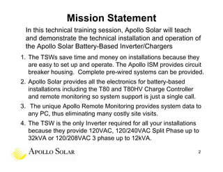
Apollo Solar's technical training session focuses on the installation and operation of their True Sine Wave (TSW) inverter/chargers, highlighting their efficiency and ease of use. The training covers off-grid power system design, safety precautions, and the various configurations available for the inverters, including mounting options and remote monitoring capabilities. The document outlines specifications for the TSW3224 and TSW4048 models, detailing their power ratings, voltage configurations, and key components for effective operation.


![Inverter Display
We noted that only one of the other Inverters in
our market has an internal display.
(The Schneider XW is the only [Off Grid] Inverter
with any display and that is just a 3 digit LED
for inverter watts and charge current only.)
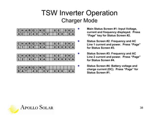
We designed the TSW with an internal 2x16 LCD
which shows all the critical current values:
• AC Output Voltage
• Mode: Inverting or Charging
• AC Output Current
• Charging Current
• AC Output Power
• Error Codes
• AC Output Frequency
• ID Address
• DC Battery Voltage
• When stacked, the Master
• DC Battery Current shows Total System values
33](https://image.slidesharecdn.com/apollosolartswinvertertrainingfornabcepconted2011020311-110325132436-phpapp02/85/Apollo-Solar-TSW-Inverter-Training-33-320.jpg)