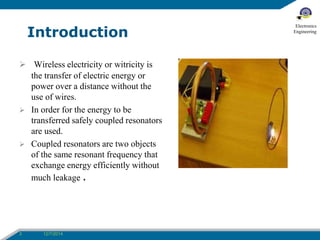
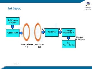
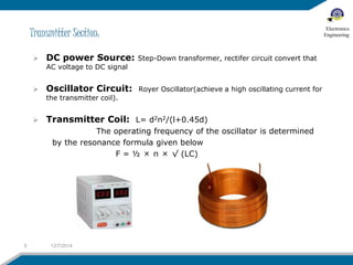
BALOCHISTAN UNIVERSITY OF INFORMATION TECHNOLOGY, ENGINEERING & 
MANAGEMENT SCIENCES
Group Members: 
2 12/7/2014 
Electronics 
Engineering
Introduction 
 Wireless electricity or witricity is 
the transfer of electric energy or 
power over a distance without the 
use of wires. 
 In order for the energy to be 
transferred safely coupled resonators 
are used. 
 Coupled resonators are two objects 
of the same resonant frequency that 
exchange energy efficiently without 
much leakage . 
3 12/7/2014 
Electronics 
Engineering
Block Diagram: 
4 12/7/2014 
Electronics 
Engineering
Transmitter Section: 
 DC power Source: Step-Down transformer, rectifer circuit convert that 
AC voltage to DC signal 
 Oscillator Circuit: Royer Oscillator(achieve a high oscillating current for 
the transmitter coil). 
 Transmitter Coil: L= d2n2/(l+0.45d) 
The operating frequency of the oscillator is determined 
by the resonance formula given below 
F = ½ × π × √ (LC) 
5 12/7/2014 
Electronics 
Engineering
Receiver Section: 
 Receiver coil: 
 Rectifier circuit and a voltage regulator IC: LM 7805 voltage 
regulator IC 
 The rectifier circuit in the receiver section converts this AC 
voltage in to DC 
6 12/7/2014 
Electronics 
Engineering
METHODS USED FOR WIRELESS POWER 
TRANSMISSION 
7 12/7/2014 
Electronics 
Engineering 
 Far Field Electricity Transmission 
 Radio/Microwave Power transmission 
 Laser Power Transmission 
 Near Field Electricity Transmission 
 Inductive Charging 
 Evanescent/Resonant Wave Coupling
INDUCTION (INDUCTIVE COUPLING): 
• The simplest example for wireless energy 
transfer using this method is the electrical 
transformer. 
• The main drawback of this method is the short 
range. 
• A larger, stronger field can be used for energy 
transfer over large distance, but this 
process is extremely inefficient. Since magnetic 
field spreads in all direction, making 
a large wastage of energy. 
8 12/7/2014 
Electronics 
Engineering
 Power is transmitted when the coils 
have same resonant frequency. 
 By using resonant induction one coil 
can send electricity to several 
receiving coils as long as they all 
resonate at same frequency. 
Resonance : It is the tendency of a system to 
oscillate with larger amplitude at some frequencies 
than at others. 
9 12/7/2014 
Electronics 
Engineering
Why not wires?? 
 As per studies, most electrical energy transfer is through 
wires. 
 Most of the energy loss is during transmission 
 On an average, more than30% 
 In Pakistan, it exceeds by 40% 
Why not batteries?? 
 Estimated that 40 billion 
batteries per year add to the 
e-waste burden. And of course its 
not a good sign. 
10 12/7/2014 
Electronics 
Engineering
Advantages and Hurdles 
 It can do away with costly grids and substations. 
 Homes and cities can be provided power wireless from a central 
transmission point. 
 Battery operated devices will never run out of power. 
 we can have cars that run non-stop with full battery charge. 
 We will never have to go to charging station. 
 Aircraft can fly nonstop with no need to refuel. 
 The future highway could have inductive coils imbedded in the road. 
Hurdles/ Disadvantages: 
 Biological Drawbacks (line of sight of microwave and Laser signal). 
 Economic cost. 
 Less efficiency. 
 Short distance.(2cm) 
11 12/7/2014 
Electronics 
Engineering
Scope 
no need of power cables. 
no need of charging batteries, or 
buying new batteries for your 
electrical gadgets. 
12 01/12/2014 
Electronics 
Engineering
Gantt Chart 
13 12/7/2014 
Electronics 
Engineering
References: 
 A next generation power transmission system”, International Journal 
of Computer Applications (0975 – 8887) (Volume 1 – No. 13) 
 Witricity 
 Peter Vaessen,” Wireless Power Transmission”, Leonardo Energy, 
September 2009 11/2/14 Wireless Power 
 www.wikipedia.com 
 http://www.sciencedirect.com/science/journals 
14 12/7/2014 
Electronics 
Engineering
Electronics 
Engineering 
Questions 
?

Wireless power transmission via resonance coupling.

  • 1.
    BALOCHISTAN UNIVERSITY OFINFORMATION TECHNOLOGY, ENGINEERING & MANAGEMENT SCIENCES
  • 2.
    Group Members: 212/7/2014 Electronics Engineering
  • 3.
    Introduction  Wirelesselectricity or witricity is the transfer of electric energy or power over a distance without the use of wires.  In order for the energy to be transferred safely coupled resonators are used.  Coupled resonators are two objects of the same resonant frequency that exchange energy efficiently without much leakage . 3 12/7/2014 Electronics Engineering
  • 4.
    Block Diagram: 412/7/2014 Electronics Engineering
  • 5.
    Transmitter Section: DC power Source: Step-Down transformer, rectifer circuit convert that AC voltage to DC signal  Oscillator Circuit: Royer Oscillator(achieve a high oscillating current for the transmitter coil).  Transmitter Coil: L= d2n2/(l+0.45d) The operating frequency of the oscillator is determined by the resonance formula given below F = ½ × π × √ (LC) 5 12/7/2014 Electronics Engineering
  • 6.
    Receiver Section: Receiver coil:  Rectifier circuit and a voltage regulator IC: LM 7805 voltage regulator IC  The rectifier circuit in the receiver section converts this AC voltage in to DC 6 12/7/2014 Electronics Engineering
  • 7.
    METHODS USED FORWIRELESS POWER TRANSMISSION 7 12/7/2014 Electronics Engineering  Far Field Electricity Transmission  Radio/Microwave Power transmission  Laser Power Transmission  Near Field Electricity Transmission  Inductive Charging  Evanescent/Resonant Wave Coupling
  • 8.
    INDUCTION (INDUCTIVE COUPLING): • The simplest example for wireless energy transfer using this method is the electrical transformer. • The main drawback of this method is the short range. • A larger, stronger field can be used for energy transfer over large distance, but this process is extremely inefficient. Since magnetic field spreads in all direction, making a large wastage of energy. 8 12/7/2014 Electronics Engineering
  • 9.
     Power istransmitted when the coils have same resonant frequency.  By using resonant induction one coil can send electricity to several receiving coils as long as they all resonate at same frequency. Resonance : It is the tendency of a system to oscillate with larger amplitude at some frequencies than at others. 9 12/7/2014 Electronics Engineering
  • 10.
    Why not wires??  As per studies, most electrical energy transfer is through wires.  Most of the energy loss is during transmission  On an average, more than30%  In Pakistan, it exceeds by 40% Why not batteries??  Estimated that 40 billion batteries per year add to the e-waste burden. And of course its not a good sign. 10 12/7/2014 Electronics Engineering
  • 11.
    Advantages and Hurdles  It can do away with costly grids and substations.  Homes and cities can be provided power wireless from a central transmission point.  Battery operated devices will never run out of power.  we can have cars that run non-stop with full battery charge.  We will never have to go to charging station.  Aircraft can fly nonstop with no need to refuel.  The future highway could have inductive coils imbedded in the road. Hurdles/ Disadvantages:  Biological Drawbacks (line of sight of microwave and Laser signal).  Economic cost.  Less efficiency.  Short distance.(2cm) 11 12/7/2014 Electronics Engineering
  • 12.
    Scope no needof power cables. no need of charging batteries, or buying new batteries for your electrical gadgets. 12 01/12/2014 Electronics Engineering
  • 13.
    Gantt Chart 1312/7/2014 Electronics Engineering
  • 14.
    References:  Anext generation power transmission system”, International Journal of Computer Applications (0975 – 8887) (Volume 1 – No. 13)  Witricity  Peter Vaessen,” Wireless Power Transmission”, Leonardo Energy, September 2009 11/2/14 Wireless Power  www.wikipedia.com  http://www.sciencedirect.com/science/journals 14 12/7/2014 Electronics Engineering
  • 15.