SlideShare a Scribd company logo
Two-Peg Test: Method for checking and recalibrating a level or transit
This method is either for an optical or digital level, or a transit being used as a level. If this error
is corrected with a transit, it also improves the accuracy of its vertical angle readings.
The two-peg test is very simple, but provides a way to test the accuracy of a level, and if you
know which screw to turn (for analog instruments) or menu to follow (for the digital level), you
can adjust it to remove the error. See specific instrument instructions for making adjustments.
The basic principle is that since the error in level readings results from the instrument not
sighting exactly horizontally, is thus looking up or down at some angle, and that this angle is the
same whichever way it's sighting: if you place the instrument exactly midway between two rod
sightings, the vertical error reading on the rod is the same for each, thus the difference in
reading between the rods will still give you an accurate elevation difference. Knowing this, we
can accurately determine the elevation of B relative to A above. If we then move the instrument
to sight from A to B, with the instrument exactly on a reading at A, we can detect the error at that
distance, and can adjust the reading to give us the true reading predicted for B.
Process:
1. In reasonably level terrain, mark out two rod positions (A and B) on stable surfaces about 30
m apart, and set up the instrument exactly midway between them at C. A good place is along
a sidewalk (preferably in a shaded area, or on an overcast day, to avoid optical problems
from heat-derived air turbulence), using sidewalk chalk to mark your points.
2. Sight to A to get a rod reading, then to B to get a reading. Assign zero to A, and derive B as
A-B. Say we get 1.524 at A and 1.501 at B, the elevation at B is 0.023. (It doesn't matter
what the elevation above sea level is – we only need what its elevation is relative to A.)
3. Move the instrument to ~3m from position A, and get a new reading to A. Subtract the
elevation at B (0.023) to get the foresight you should expect to get. Say your reading at A is
1.257:
FScomputed = 1.257 – 0.023 = 1.234
4. Now sight to B to get a reading, and compare it to the expected reading.
A BC
D A B
15 m15 m
Computed FS
Actual FS
5. If there's an error, your FSactual will be different from this, and requires an adjustment. Your
task is to move it up or down until you get the computed FS.
 For analog instruments, you can adjust the cross hairs by (a) loosening the top capstan
screw that allows it to move up, or the bottom capstan screw that allows it to move down;
then (b) tightening to other capstan screw. Think of the capstan screws as two ends of a
continuously adjusting screw – you're pulling (loosening) with one and simultaneously
pushing (tightening) with the other. The capstan screws are turned with adjustment tools
(or drill bits, if the tools are missing) that are inserted in the side of the capstan so you
can turn the screw tiny amounts. For the Sokkisha level, the capstans are just behind the
eyepiece, and can be exposed by unscrewing the cover that is slightly larger than the
eyepiece.
 For digital instruments, you select things from menus, while you go through the process.
You'll need to look this up. The following is from the Leica Sprinter manual:
1. With the level set up at the midpoint (C), activate the "Check and Adjust" program by
pressing MENU-ADJUSTMENT. Should display cryptic instructions like "ADJUST
(1/4)" with an arrow labeled MEAS pointing back to the rod.
2. Aim at the Rod at A and press the MEAS key. Measurement display, press ENTER
key to accept/confirm.
3. Aim at B and press MEAS (step 2/4). The measurement displays; press ENTER to
accept/confirm.
4. Shift the Sprinter towards rod A, about 3 m away and make a reading to B again (this
is not the order we did things above); this will be adjustment reading 3/4.
5. Aim at rod A and press MEAS (4/4). The measurement displays; press ENTER to
accept/confirm. The new "collimation error" is displayed in seconds of angle and
corresponding dH vertical error in mm at that distance. To accept the correction,
press the ENTER key. The manual then says:
"If the reticle adjustment is required, reverse the staff B for the E scale bar reading then
adjust the reticle using the tool provided by following through the given instructions.
In the event where warning message e.g. "Invalid Measurement" is displayed for any
adjustment measurement, carry on measuring until a successful measurement is obtained
(Presumably instrument is set up correctly and external conditions are conducive) and
press ENTER key to accept the measurement.
"To quit the Adjustment program (when the measurement is invalid) by pressing ESC key;
press ESC key once, the display will go to last Adjustment step. Press ESC key twice, the
display will return to the Menu. Press ESC key thrice, the display will exit to the default
measuring mode."
It's probably a good idea to try this again to see if the adjustment worked.

More Related Content

What's hot

Site surveying report (theodolite)
Site surveying report (theodolite)Site surveying report (theodolite)
Site surveying report (theodolite)
Erik Ong
 
Introduction to Surveying LEVELLING PROCEDURES
Introduction to Surveying LEVELLING PROCEDURESIntroduction to Surveying LEVELLING PROCEDURES
Introduction to Surveying LEVELLING PROCEDURES
Bahzad5
 

What's hot (20)

Traversing
TraversingTraversing
Traversing
 
Contouring Report
Contouring ReportContouring Report
Contouring Report
 
SITE SURVEYING: Transversing
SITE SURVEYING: TransversingSITE SURVEYING: Transversing
SITE SURVEYING: Transversing
 
Tacheometry @surveyingreport
Tacheometry @surveyingreportTacheometry @surveyingreport
Tacheometry @surveyingreport
 
Contouring in "Survey & Levelling".
Contouring in "Survey & Levelling".Contouring in "Survey & Levelling".
Contouring in "Survey & Levelling".
 
Site Surveying Report 2 (Traversing)
Site Surveying Report 2 (Traversing)Site Surveying Report 2 (Traversing)
Site Surveying Report 2 (Traversing)
 
Assignment 2 - Traverse
Assignment 2 - TraverseAssignment 2 - Traverse
Assignment 2 - Traverse
 
Tranverse report
Tranverse report Tranverse report
Tranverse report
 
Site surveying report (theodolite)
Site surveying report (theodolite)Site surveying report (theodolite)
Site surveying report (theodolite)
 
levelling and contouring
levelling and contouringlevelling and contouring
levelling and contouring
 
Traversing final-report
Traversing final-reportTraversing final-report
Traversing final-report
 
levelling and contouring
 levelling and  contouring levelling and  contouring
levelling and contouring
 
Site Surveying Report - Traversing
Site Surveying Report - TraversingSite Surveying Report - Traversing
Site Surveying Report - Traversing
 
Introduction to Surveying LEVELLING PROCEDURES
Introduction to Surveying LEVELLING PROCEDURESIntroduction to Surveying LEVELLING PROCEDURES
Introduction to Surveying LEVELLING PROCEDURES
 
Setting out of curve (Survey)
Setting out of curve (Survey)Setting out of curve (Survey)
Setting out of curve (Survey)
 
Assignment 1 - Levelling
Assignment 1 - LevellingAssignment 1 - Levelling
Assignment 1 - Levelling
 
engineering survey 1 report levelling
engineering survey 1 report levellingengineering survey 1 report levelling
engineering survey 1 report levelling
 
Lecture 1 precise levelling
Lecture 1 precise levellingLecture 1 precise levelling
Lecture 1 precise levelling
 
REPORT SURVEY RANGING CURVE CIVIL ENGINEERING.pdf
REPORT SURVEY RANGING CURVE CIVIL ENGINEERING.pdfREPORT SURVEY RANGING CURVE CIVIL ENGINEERING.pdf
REPORT SURVEY RANGING CURVE CIVIL ENGINEERING.pdf
 
ROAD PROFILING, CROSS SECTION & SETTING OUT SEWER LINE
ROAD  PROFILING, CROSS SECTION & SETTING OUT SEWER LINEROAD  PROFILING, CROSS SECTION & SETTING OUT SEWER LINE
ROAD PROFILING, CROSS SECTION & SETTING OUT SEWER LINE
 

Similar to Two pegtest

Pressure Overview Of Measurement And Calibration
Pressure Overview Of Measurement And CalibrationPressure Overview Of Measurement And Calibration
Pressure Overview Of Measurement And Calibration
Asep Herman
 
Total station setup and operation
Total station setup and operationTotal station setup and operation
Total station setup and operation
Muhammad Adi K
 
Lecture2
Lecture2Lecture2
Lecture2
jbusse
 
micro-optic-theodolite.pdf
micro-optic-theodolite.pdfmicro-optic-theodolite.pdf
micro-optic-theodolite.pdf
FaizanSolanki
 
PHYS 221Lab 1 - Acceleration Due to GravityPlease work in g.docx
PHYS 221Lab 1 - Acceleration Due to GravityPlease work in g.docxPHYS 221Lab 1 - Acceleration Due to GravityPlease work in g.docx
PHYS 221Lab 1 - Acceleration Due to GravityPlease work in g.docx
mattjtoni51554
 
Lecture_3_The Principles of Levelling_fec6a71b84edc28ee2998f7ced9ddf68.pdf
Lecture_3_The Principles of Levelling_fec6a71b84edc28ee2998f7ced9ddf68.pdfLecture_3_The Principles of Levelling_fec6a71b84edc28ee2998f7ced9ddf68.pdf
Lecture_3_The Principles of Levelling_fec6a71b84edc28ee2998f7ced9ddf68.pdf
AlwandBarzani
 

Similar to Two pegtest (20)

Surveying_en.pdf
Surveying_en.pdfSurveying_en.pdf
Surveying_en.pdf
 
Surveying_en.pdf
Surveying_en.pdfSurveying_en.pdf
Surveying_en.pdf
 
Pressure Overview Of Measurement And Calibration
Pressure Overview Of Measurement And CalibrationPressure Overview Of Measurement And Calibration
Pressure Overview Of Measurement And Calibration
 
Total station setup and operation
Total station setup and operationTotal station setup and operation
Total station setup and operation
 
Site surveying report 1
Site surveying report 1Site surveying report 1
Site surveying report 1
 
Carl-Zeiss Coordinate measuring machine report (O-INSPECT 543)
Carl-Zeiss Coordinate measuring machine report (O-INSPECT 543)Carl-Zeiss Coordinate measuring machine report (O-INSPECT 543)
Carl-Zeiss Coordinate measuring machine report (O-INSPECT 543)
 
Fadal Survey Menu Manual
Fadal Survey Menu ManualFadal Survey Menu Manual
Fadal Survey Menu Manual
 
To Experimental Study for Comparison Theodolite and Total Station
To Experimental Study for Comparison Theodolite and Total Station To Experimental Study for Comparison Theodolite and Total Station
To Experimental Study for Comparison Theodolite and Total Station
 
Advanced surveying equipment ppt
Advanced surveying equipment pptAdvanced surveying equipment ppt
Advanced surveying equipment ppt
 
Summerlin Map Reading
Summerlin Map ReadingSummerlin Map Reading
Summerlin Map Reading
 
Lecture2
Lecture2Lecture2
Lecture2
 
micro-optic-theodolite.pdf
micro-optic-theodolite.pdfmicro-optic-theodolite.pdf
micro-optic-theodolite.pdf
 
Group 1.pptx
Group 1.pptxGroup 1.pptx
Group 1.pptx
 
Altimetria (1ra clase)
Altimetria (1ra clase)Altimetria (1ra clase)
Altimetria (1ra clase)
 
PHYS 221Lab 1 - Acceleration Due to GravityPlease work in g.docx
PHYS 221Lab 1 - Acceleration Due to GravityPlease work in g.docxPHYS 221Lab 1 - Acceleration Due to GravityPlease work in g.docx
PHYS 221Lab 1 - Acceleration Due to GravityPlease work in g.docx
 
1. Practical assessment-Carry out levelling operations
1. Practical assessment-Carry out levelling operations1. Practical assessment-Carry out levelling operations
1. Practical assessment-Carry out levelling operations
 
Practical assessment 1-Carry out levelling operations
Practical assessment 1-Carry out levelling operationsPractical assessment 1-Carry out levelling operations
Practical assessment 1-Carry out levelling operations
 
lecture_(1)_(Leveling-Centering-Tilting-FUNC-total station
lecture_(1)_(Leveling-Centering-Tilting-FUNC-total stationlecture_(1)_(Leveling-Centering-Tilting-FUNC-total station
lecture_(1)_(Leveling-Centering-Tilting-FUNC-total station
 
Theodolite and Its Uses
Theodolite and Its UsesTheodolite and Its Uses
Theodolite and Its Uses
 
Lecture_3_The Principles of Levelling_fec6a71b84edc28ee2998f7ced9ddf68.pdf
Lecture_3_The Principles of Levelling_fec6a71b84edc28ee2998f7ced9ddf68.pdfLecture_3_The Principles of Levelling_fec6a71b84edc28ee2998f7ced9ddf68.pdf
Lecture_3_The Principles of Levelling_fec6a71b84edc28ee2998f7ced9ddf68.pdf
 

Recently uploaded

Digital Signal Processing Lecture notes n.pdf
Digital Signal Processing Lecture notes n.pdfDigital Signal Processing Lecture notes n.pdf
Digital Signal Processing Lecture notes n.pdf
AbrahamGadissa
 
Online blood donation management system project.pdf
Online blood donation management system project.pdfOnline blood donation management system project.pdf
Online blood donation management system project.pdf
Kamal Acharya
 
Automobile Management System Project Report.pdf
Automobile Management System Project Report.pdfAutomobile Management System Project Report.pdf
Automobile Management System Project Report.pdf
Kamal Acharya
 
Hall booking system project report .pdf
Hall booking system project report  .pdfHall booking system project report  .pdf
Hall booking system project report .pdf
Kamal Acharya
 

Recently uploaded (20)

Explosives Industry manufacturing process.pdf
Explosives Industry manufacturing process.pdfExplosives Industry manufacturing process.pdf
Explosives Industry manufacturing process.pdf
 
KIT-601 Lecture Notes-UNIT-5.pdf Frame Works and Visualization
KIT-601 Lecture Notes-UNIT-5.pdf Frame Works and VisualizationKIT-601 Lecture Notes-UNIT-5.pdf Frame Works and Visualization
KIT-601 Lecture Notes-UNIT-5.pdf Frame Works and Visualization
 
Pharmacy management system project report..pdf
Pharmacy management system project report..pdfPharmacy management system project report..pdf
Pharmacy management system project report..pdf
 
Digital Signal Processing Lecture notes n.pdf
Digital Signal Processing Lecture notes n.pdfDigital Signal Processing Lecture notes n.pdf
Digital Signal Processing Lecture notes n.pdf
 
Online resume builder management system project report.pdf
Online resume builder management system project report.pdfOnline resume builder management system project report.pdf
Online resume builder management system project report.pdf
 
Online blood donation management system project.pdf
Online blood donation management system project.pdfOnline blood donation management system project.pdf
Online blood donation management system project.pdf
 
HYDROPOWER - Hydroelectric power generation
HYDROPOWER - Hydroelectric power generationHYDROPOWER - Hydroelectric power generation
HYDROPOWER - Hydroelectric power generation
 
Halogenation process of chemical process industries
Halogenation process of chemical process industriesHalogenation process of chemical process industries
Halogenation process of chemical process industries
 
ASME IX(9) 2007 Full Version .pdf
ASME IX(9)  2007 Full Version       .pdfASME IX(9)  2007 Full Version       .pdf
ASME IX(9) 2007 Full Version .pdf
 
Automobile Management System Project Report.pdf
Automobile Management System Project Report.pdfAutomobile Management System Project Report.pdf
Automobile Management System Project Report.pdf
 
Furniture showroom management system project.pdf
Furniture showroom management system project.pdfFurniture showroom management system project.pdf
Furniture showroom management system project.pdf
 
Natalia Rutkowska - BIM School Course in Kraków
Natalia Rutkowska - BIM School Course in KrakówNatalia Rutkowska - BIM School Course in Kraków
Natalia Rutkowska - BIM School Course in Kraków
 
The Ultimate Guide to External Floating Roofs for Oil Storage Tanks.docx
The Ultimate Guide to External Floating Roofs for Oil Storage Tanks.docxThe Ultimate Guide to External Floating Roofs for Oil Storage Tanks.docx
The Ultimate Guide to External Floating Roofs for Oil Storage Tanks.docx
 
A case study of cinema management system project report..pdf
A case study of cinema management system project report..pdfA case study of cinema management system project report..pdf
A case study of cinema management system project report..pdf
 
İTÜ CAD and Reverse Engineering Workshop
İTÜ CAD and Reverse Engineering WorkshopİTÜ CAD and Reverse Engineering Workshop
İTÜ CAD and Reverse Engineering Workshop
 
Scaling in conventional MOSFET for constant electric field and constant voltage
Scaling in conventional MOSFET for constant electric field and constant voltageScaling in conventional MOSFET for constant electric field and constant voltage
Scaling in conventional MOSFET for constant electric field and constant voltage
 
BRAKING SYSTEM IN INDIAN RAILWAY AutoCAD DRAWING
BRAKING SYSTEM IN INDIAN RAILWAY AutoCAD DRAWINGBRAKING SYSTEM IN INDIAN RAILWAY AutoCAD DRAWING
BRAKING SYSTEM IN INDIAN RAILWAY AutoCAD DRAWING
 
WATER CRISIS and its solutions-pptx 1234
WATER CRISIS and its solutions-pptx 1234WATER CRISIS and its solutions-pptx 1234
WATER CRISIS and its solutions-pptx 1234
 
A CASE STUDY ON ONLINE TICKET BOOKING SYSTEM PROJECT.pdf
A CASE STUDY ON ONLINE TICKET BOOKING SYSTEM PROJECT.pdfA CASE STUDY ON ONLINE TICKET BOOKING SYSTEM PROJECT.pdf
A CASE STUDY ON ONLINE TICKET BOOKING SYSTEM PROJECT.pdf
 
Hall booking system project report .pdf
Hall booking system project report  .pdfHall booking system project report  .pdf
Hall booking system project report .pdf
 

Two pegtest

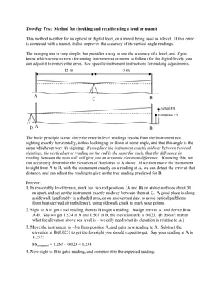
  • 1. Two-Peg Test: Method for checking and recalibrating a level or transit This method is either for an optical or digital level, or a transit being used as a level. If this error is corrected with a transit, it also improves the accuracy of its vertical angle readings. The two-peg test is very simple, but provides a way to test the accuracy of a level, and if you know which screw to turn (for analog instruments) or menu to follow (for the digital level), you can adjust it to remove the error. See specific instrument instructions for making adjustments. The basic principle is that since the error in level readings results from the instrument not sighting exactly horizontally, is thus looking up or down at some angle, and that this angle is the same whichever way it's sighting: if you place the instrument exactly midway between two rod sightings, the vertical error reading on the rod is the same for each, thus the difference in reading between the rods will still give you an accurate elevation difference. Knowing this, we can accurately determine the elevation of B relative to A above. If we then move the instrument to sight from A to B, with the instrument exactly on a reading at A, we can detect the error at that distance, and can adjust the reading to give us the true reading predicted for B. Process: 1. In reasonably level terrain, mark out two rod positions (A and B) on stable surfaces about 30 m apart, and set up the instrument exactly midway between them at C. A good place is along a sidewalk (preferably in a shaded area, or on an overcast day, to avoid optical problems from heat-derived air turbulence), using sidewalk chalk to mark your points. 2. Sight to A to get a rod reading, then to B to get a reading. Assign zero to A, and derive B as A-B. Say we get 1.524 at A and 1.501 at B, the elevation at B is 0.023. (It doesn't matter what the elevation above sea level is – we only need what its elevation is relative to A.) 3. Move the instrument to ~3m from position A, and get a new reading to A. Subtract the elevation at B (0.023) to get the foresight you should expect to get. Say your reading at A is 1.257: FScomputed = 1.257 – 0.023 = 1.234 4. Now sight to B to get a reading, and compare it to the expected reading. A BC D A B 15 m15 m Computed FS Actual FS
  • 2. 5. If there's an error, your FSactual will be different from this, and requires an adjustment. Your task is to move it up or down until you get the computed FS.  For analog instruments, you can adjust the cross hairs by (a) loosening the top capstan screw that allows it to move up, or the bottom capstan screw that allows it to move down; then (b) tightening to other capstan screw. Think of the capstan screws as two ends of a continuously adjusting screw – you're pulling (loosening) with one and simultaneously pushing (tightening) with the other. The capstan screws are turned with adjustment tools (or drill bits, if the tools are missing) that are inserted in the side of the capstan so you can turn the screw tiny amounts. For the Sokkisha level, the capstans are just behind the eyepiece, and can be exposed by unscrewing the cover that is slightly larger than the eyepiece.  For digital instruments, you select things from menus, while you go through the process. You'll need to look this up. The following is from the Leica Sprinter manual: 1. With the level set up at the midpoint (C), activate the "Check and Adjust" program by pressing MENU-ADJUSTMENT. Should display cryptic instructions like "ADJUST (1/4)" with an arrow labeled MEAS pointing back to the rod. 2. Aim at the Rod at A and press the MEAS key. Measurement display, press ENTER key to accept/confirm. 3. Aim at B and press MEAS (step 2/4). The measurement displays; press ENTER to accept/confirm. 4. Shift the Sprinter towards rod A, about 3 m away and make a reading to B again (this is not the order we did things above); this will be adjustment reading 3/4. 5. Aim at rod A and press MEAS (4/4). The measurement displays; press ENTER to accept/confirm. The new "collimation error" is displayed in seconds of angle and corresponding dH vertical error in mm at that distance. To accept the correction, press the ENTER key. The manual then says: "If the reticle adjustment is required, reverse the staff B for the E scale bar reading then adjust the reticle using the tool provided by following through the given instructions. In the event where warning message e.g. "Invalid Measurement" is displayed for any adjustment measurement, carry on measuring until a successful measurement is obtained (Presumably instrument is set up correctly and external conditions are conducive) and press ENTER key to accept the measurement. "To quit the Adjustment program (when the measurement is invalid) by pressing ESC key; press ESC key once, the display will go to last Adjustment step. Press ESC key twice, the display will return to the Menu. Press ESC key thrice, the display will exit to the default measuring mode." It's probably a good idea to try this again to see if the adjustment worked.