SlideShare a Scribd company logo
1 of 6
Download to read offline
The PC Boot Process - Windows XP.


                                               The power supply performs a self-
                                               test. When all voltages and current
                                               levels are acceptable, the supply
                                               indicates that the power is stable and
         Power supply switched on.
                                               sends the Power Good signal to the
                                               processor. The time from switch-on to
                                               Power Good is usually between .1 and
                                               .5 seconds.


                                               With the arrival of the Power Good
         The microprocessor timer chip         signal the timer chip stops sending
         receives the Power Good signal.       reset signals to the processor allowing
                                               the CPU to begin operations.


                                               The CPU loads the ROM BIOS starting
                                               at ROM memory address FFFF:0000
                                               which is only 16 bytes from the top of
         The CPU starts executing the ROM
                                               ROM memory. As such it contains
         BIOS code.
                                               only a JMP (jump) instruction that
                                               points to the actual address of the
                                               ROM BIOS code.


                                               Any errors that occur at this point in
         The ROM BIOS performs a basic         the boot process will be reported by
         test of central hardware to verify    means of 'beep-codes' because the
         basic functionality.                  video subsystem has not yet been
                                               initialized.


                                               Video adapters provide the most
                                               common source of adapter ROM
                                               BIOS. The start-up BIOS routines
                                               scan memory addresses C000:0000
                                               through C780:0000 to find video
         The BIOS searches for adapters
                                               ROM. An error loading any adapter
         that may need to load their own
                                               ROM generates an error such as:
         ROM BIOS routines.
                                                    XXXX ROM Error

                                               where XXXX represents the segment
                                               address of the failed module.


                                               To determine whether this is a warm-
                                               start or a cold start the ROM BIOS
         The ROM BIOS checks to see if this
                                               startup routines check the value of
         is a 'cold-start' or a 'warm-start'
                                               two bytes located at memory location
                                               0000:0472. Any value other than
1234h indicates that this is a cold-
                                                     start.


                                                     The POST can be broken down into
                                                     three components:
                                                     The Video Test initializes the video
                                                     adapter, tests the video card and
             If this is a cold-start the ROM BIOS    video memory, and displays
             executes a full POST (Power On          configuration information or any
             Self Test). If this is a warm-start     errors.
             the memory test portion of the          The BIOS Identification displays the
             POST is switched off.                   BIOS version, manufacturer, and
                                                     date.
                                                     The Memory Test tests the memory
                                                     chips and displays a running sum of
                                                     installed memory.


                                                     Errors the occur during the POST can
                                                     be classified as either 'fatal' or 'non-
                                                     fatal'. A non-fatal error will typically
                                                     display an error message on screen
                                                     and allow the system to continue the
                                                     boot process. A fatal error, on the
                                                     other hand, stops the process of
                                                     booting the computer and is generally
                                                     signaled by a series of beep-codes.


                                                     CMOS (which stands for
                                                     Complementary Metal-Oxide
                                                     Semiconductor) is a small area of
             The BIOS locates and reads the          memory (64 bytes) which is
             configuration information stored in     maintained by the current of a small
             CMOS.                                   battery attached to the motherboard.
                                                     Most importantly for the ROM BIOS
                                                     startup routines CMOS indicates the
                                                     order in which drives should be
                                                     examined for an operating systems -
                                                     floppy first, CD-Rom first, or fixed
                                                     disk first.
Fixed Disk

                                                     On a fixed disk the Master Boot
                                                     Record occupies the very first sector
             If the first bootable disk is a fixed   at cylinder 0, head 0, sector 1. It is
             disk the BIOS examines the very         512 bytes in size. If this sector is
             first sector of the disk for a Master   found it is loaded into memory at
             Boot Record (MBR). For a floppy         address 0000:7C00 and tested for a
             the BIOS looks for a Boot Record        valid signature. A valid signature
             in the very first sector.               would be the value 55AAh in the last
                                                     two bytes. Lacking an MBR or a valid
                                                     signature the boot process halts with
                                                     an error message which might read:

                                                     NO ROM BASIC - SYSTEM HALTED
A Master Boot Record is made up of
                                                       two parts - the partition table which
                                                       describes the layout of the fixed disk
                                                       and the partition loader code which
                                                       includes instructions for continuing
                                                       the boot process.


                                                       The process of installing multiple
               With a valid MBR loaded into            operating systems on a single PC
               memory the BIOS transfers control       usually involves replacing the original
MBR            of the boot process to the partition    partition loader code with a Boot
               loader code that takes up most of       Loader program that allows the user
               the 512 bytes of the MBR.               to select the specific fixed disk to load
                                                       in the next step of the process


                                                       The Boot Record is also 512 bytes and
               The partition loader (or Boot           contains a table that describes the
               Loader) examines the partition          characteristics of the partition
Partition      table for a partition marked as         (number of bytes per sectors, number
Table          active. The partition loader then       of sectors per cluster, etc.) and also
               searches the very first sector of       the jump code that locates the first of
               that partition for a Boot Record.       the operating system files (IO.SYS in
                                                       DOS).
Operating
System
                                                       The loading of Windows XP is
                                                       controlled by the file NTLDR which is
                                                       a hidden, system file that resides in
                                                       the root directory of the system
               The active partition's boot record is
                                                       partition. NTLDR will load XP in four
               checked for a valid boot signature
Boot Record                                            stages:
               and if found the boot sector code is
               executed as a program.
                                                       1)   Initial Boot Loader Phase
                                                       2)   Operating System selection
                                                       3)   Hardware Detection
                                                       4)   Configuration Selection


              During the initial phase NTLDR
              switches the processor from real-
              mode to protected mode which
              places the processor in 32-bit
              memory mode and turns memory             Windows XP supports partitions
NTLDR
              paging on. It then loads the             formatted with either the FAT-16,
Initial Phase
              appropriate mini-file system             FAT-32, or NTFS file system.
              drivers to allow NTLDR to load files
              from a partition formatted with any
              of the files systems supported by
              XP.


NTLDR        If the file BOOT.INI is located in        If the file BOOT.INI is not found in the
OS Selection the root directory NTLDR will read        root directory NTLDR will continue the
BOOT.INI     it's contents into memory. If             boot sequence and attempt to load XP
BOOT.INI contains entries for more    from the first partition of the first
              than one operating system NTLDR       disk, typically C:.
              will stop the boot sequence at this
              point, display a menu of choices,
              and wait for a specified period of
              time for the user to make a
              selection.


                                                    After each successful boot sequence
              Assuming that the operating           XP makes a copy of the current
              system being loaded is Windows        combination of driver and system
              NT, 2000, or XP pressing F8 at this   settings and stores it as the Last
F8            stage of the boot sequence to         Known Good Configuration. This
              display various boot options          collection of settings can be used to
              including "Safe Mode" and "Last       boot the system subsequently if the
              Known Good Configuration"             installation of some new device has
                                                    caused a boot failure.


              If the selected operating system is   NTDETECT.COM collects a list of
              XP, NTLDR will continue the boot      currently installed hardware
NTLDR
              process by locating and loading the   components and returns this list for
Hardware
              DOS based NTDETECT.COM                later inclusion in the registry under
Detection
              program to perform hardware           the HKEY_LOCAL_MACHINE
              detection.                            HARDWARE key.


              If this computer has more than
              one defined Hardware Profile the
NTLDR                                               Lacking more than one Hardware
              NTLDR program will stop at this
Configuration                                       Profile NTLDR will skip this step and
              point and display the Hardware
Selection                                           not display this menu.
              Profiles/Configuration Recovery
              menu.


                                                    During the loading of the kernel (but
                                                    before it is initialized) NTLDR remains
                                                    in control of the computer. The screen
                                                    is cleared and a series of white
              After selecting a hardware
                                                    rectangles progress across the bottom
              configuration (if necessary) NTLDR
Kernel Load                                         of the screen. NTLDR also loads the
              begins loading the XP kernel
                                                    Hardware Abstraction Layer
              (NTOSKRNL.EXE).
                                                    (HAL.DLL) at this time which will
                                                    insulate the kernel from hardware.
                                                    Both files are located in the
                                                    system32 directory.


                                                    Every driver has a registry subkey
                                                    entry under HKEY_LOCAL_MACHINE
              NTLDR now loads device drivers
NTLDR                                               SYSTEMServices. Any driver that
              that are marked as boot devices.
Boot                                                has a Start value of
              With the loading of these drivers
Device                                              SERVICE_BOOT_START is considered
              NTLDR relinquishes control of the
Drivers                                             a device to start at boot up. A period
              computer.
                                                    is printed to the screen for each
                                                    loaded file (unless the /SOS switch is
used in which case file names are
                                                     printed.


                                                     XP disables interrupts during phase 0
                                                     and enables them before phase 1.
                                                     The HAL is called to prepare the
                                                     interrupt controller; the Memory
                                                     Manager, Object Manager, Security
               NTOSKRNL goes through two             Reference Monitor, and Process
               phases in its boot process - phase    Manager are initialized.
               0 and phase 1. Phase 0 initializes
               just enough of the microkernel and    Phase 1 begins when the HAL is called
               Executive subsystems so that basic    to prepare the system to accept
               services required for the             interrupts from devices. If more than
               completion of initialization become   one processor is present the
Kernel
                                                     additional processors are initialized at
Initialization available.. At this point, the
               system display a graphical screen     this point. All Executive subsystems
               with a status bar indicating load     are reinitialized in the following order:
               status.
                                                     1)   Object Manager
                                                     2)   Executive
                                                     3)   Microkernel
                                                     4)   Security Reference Monitor
                                                     5)   Memory Manager
                                                     6)   Cache Manager
                                                     7)   LPCS
                                                     8)   I/O Manager
                                                     9)   Process Manager


            The initialization of I/O Manager
            begins the process of loading all
            the systems driver files. Picking up     The failure of a driver to load may
            where NTLDR left off, it first           prompt NT to reboot and try to start
I/O Manager
            finishes the loading of boot             the system using the values stored in
            devices. Next it assembles a             the Last Known Good Configuration.
            prioritized list of drivers and
            attempts to load each in turn.


                                                     SMSS runs in user-mode but unlike
               The last task for phase 1             other user-mode applications SMSS is
               initialization of the kernel is to    considered a trusted part of the
               launch the Session Manager            operating system and is also a native
SMSS           Subsystem (SMSS). SMSS is             application (it uses only core
               responsible for creating the user-    Executive functions). These two
               mode environment that provides        features allow SMSS to start the
               the visible interface to NT.          graphics subsystem and login
                                                     processes.


                                                     Shortly after win32k.sys starts it
               SMSS loads the win32k.sys device      switches the screen into graphics
win32k.sys     driver which implements the           mode. The Services Subsystem now
               Win32 graphics subsystem.             starts all services mark as Auto Start.
                                                     Once all devices and services are
started the boot is deemed successful
                                            and this configuration is saved as the
                                            Last Known Good Configuration.


        The XP boot process is not
        considered complete until a user
        has successfully logged onto the
        system. The process is begun by     This dialog box appears at
        the WINLOGON.EXE file which is      approximately the time that the
Logon
        loaded as a service by the kernel   Services Subsystem starts the
        and continued by the Local          network service.
        Security Authority (LSASS.EXE)
        which displays the logon dialog
        box.

More Related Content

Similar to Xp boot process

Similar to Xp boot process (20)

COMPUTER Bios
COMPUTER BiosCOMPUTER Bios
COMPUTER Bios
 
Chapter 3 Motherboard and BIOS
Chapter 3 Motherboard and BIOSChapter 3 Motherboard and BIOS
Chapter 3 Motherboard and BIOS
 
BOOTING.ppt
BOOTING.pptBOOTING.ppt
BOOTING.ppt
 
File000124
File000124File000124
File000124
 
Bios ( Basic Input Output System )
Bios ( Basic Input Output System )Bios ( Basic Input Output System )
Bios ( Basic Input Output System )
 
Bios
BiosBios
Bios
 
bios-111114014139-phpapp02-130920074327-phpapp02.pptx
bios-111114014139-phpapp02-130920074327-phpapp02.pptxbios-111114014139-phpapp02-130920074327-phpapp02.pptx
bios-111114014139-phpapp02-130920074327-phpapp02.pptx
 
bios-111114014139-phpapp02-130920074327-phpapp02 (1).pptx
bios-111114014139-phpapp02-130920074327-phpapp02 (1).pptxbios-111114014139-phpapp02-130920074327-phpapp02 (1).pptx
bios-111114014139-phpapp02-130920074327-phpapp02 (1).pptx
 
Bios bc
Bios bcBios bc
Bios bc
 
bios.docx
bios.docxbios.docx
bios.docx
 
BIOS.pptx
BIOS.pptxBIOS.pptx
BIOS.pptx
 
BIOS/UEFI
BIOS/UEFIBIOS/UEFI
BIOS/UEFI
 
booting steps of a computer
booting steps of a computerbooting steps of a computer
booting steps of a computer
 
BIOS
BIOSBIOS
BIOS
 
05 - BIOS.ppt
05 - BIOS.ppt05 - BIOS.ppt
05 - BIOS.ppt
 
itisha.pptx
itisha.pptxitisha.pptx
itisha.pptx
 
Share Harsh-Deliwala-92200938143-1DC3.pptx
Share Harsh-Deliwala-92200938143-1DC3.pptxShare Harsh-Deliwala-92200938143-1DC3.pptx
Share Harsh-Deliwala-92200938143-1DC3.pptx
 
bios-111114014139-phpapp02-130920074327-phpapp02.pptx
bios-111114014139-phpapp02-130920074327-phpapp02.pptxbios-111114014139-phpapp02-130920074327-phpapp02.pptx
bios-111114014139-phpapp02-130920074327-phpapp02.pptx
 
BIOS PRESENTATION
BIOS PRESENTATIONBIOS PRESENTATION
BIOS PRESENTATION
 
Bios vs cmos
Bios vs cmosBios vs cmos
Bios vs cmos
 

More from kinish kumar

dynamic host configuration protocol
dynamic host configuration protocoldynamic host configuration protocol
dynamic host configuration protocolkinish kumar
 
INTRODUCTION TO NETWORK OS
INTRODUCTION TO NETWORK OSINTRODUCTION TO NETWORK OS
INTRODUCTION TO NETWORK OSkinish kumar
 
Cross site scripting
Cross site scriptingCross site scripting
Cross site scriptingkinish kumar
 
Basic construction of c
Basic construction of cBasic construction of c
Basic construction of ckinish kumar
 
Transmission media
Transmission mediaTransmission media
Transmission mediakinish kumar
 

More from kinish kumar (6)

dynamic host configuration protocol
dynamic host configuration protocoldynamic host configuration protocol
dynamic host configuration protocol
 
INTRODUCTION TO NETWORK OS
INTRODUCTION TO NETWORK OSINTRODUCTION TO NETWORK OS
INTRODUCTION TO NETWORK OS
 
Cross site scripting
Cross site scriptingCross site scripting
Cross site scripting
 
Basic construction of c
Basic construction of cBasic construction of c
Basic construction of c
 
Transmission media
Transmission mediaTransmission media
Transmission media
 
Cyber crime
Cyber crimeCyber crime
Cyber crime
 

Recently uploaded

SAP Build Work Zone - Overview L2-L3.pptx
SAP Build Work Zone - Overview L2-L3.pptxSAP Build Work Zone - Overview L2-L3.pptx
SAP Build Work Zone - Overview L2-L3.pptxNavinnSomaal
 
Automating Business Process via MuleSoft Composer | Bangalore MuleSoft Meetup...
Automating Business Process via MuleSoft Composer | Bangalore MuleSoft Meetup...Automating Business Process via MuleSoft Composer | Bangalore MuleSoft Meetup...
Automating Business Process via MuleSoft Composer | Bangalore MuleSoft Meetup...shyamraj55
 
Designing IA for AI - Information Architecture Conference 2024
Designing IA for AI - Information Architecture Conference 2024Designing IA for AI - Information Architecture Conference 2024
Designing IA for AI - Information Architecture Conference 2024Enterprise Knowledge
 
Beyond Boundaries: Leveraging No-Code Solutions for Industry Innovation
Beyond Boundaries: Leveraging No-Code Solutions for Industry InnovationBeyond Boundaries: Leveraging No-Code Solutions for Industry Innovation
Beyond Boundaries: Leveraging No-Code Solutions for Industry InnovationSafe Software
 
"Subclassing and Composition – A Pythonic Tour of Trade-Offs", Hynek Schlawack
"Subclassing and Composition – A Pythonic Tour of Trade-Offs", Hynek Schlawack"Subclassing and Composition – A Pythonic Tour of Trade-Offs", Hynek Schlawack
"Subclassing and Composition – A Pythonic Tour of Trade-Offs", Hynek SchlawackFwdays
 
Install Stable Diffusion in windows machine
Install Stable Diffusion in windows machineInstall Stable Diffusion in windows machine
Install Stable Diffusion in windows machinePadma Pradeep
 
"Federated learning: out of reach no matter how close",Oleksandr Lapshyn
"Federated learning: out of reach no matter how close",Oleksandr Lapshyn"Federated learning: out of reach no matter how close",Oleksandr Lapshyn
"Federated learning: out of reach no matter how close",Oleksandr LapshynFwdays
 
"Debugging python applications inside k8s environment", Andrii Soldatenko
"Debugging python applications inside k8s environment", Andrii Soldatenko"Debugging python applications inside k8s environment", Andrii Soldatenko
"Debugging python applications inside k8s environment", Andrii SoldatenkoFwdays
 
Are Multi-Cloud and Serverless Good or Bad?
Are Multi-Cloud and Serverless Good or Bad?Are Multi-Cloud and Serverless Good or Bad?
Are Multi-Cloud and Serverless Good or Bad?Mattias Andersson
 
My Hashitalk Indonesia April 2024 Presentation
My Hashitalk Indonesia April 2024 PresentationMy Hashitalk Indonesia April 2024 Presentation
My Hashitalk Indonesia April 2024 PresentationRidwan Fadjar
 
Understanding the Laravel MVC Architecture
Understanding the Laravel MVC ArchitectureUnderstanding the Laravel MVC Architecture
Understanding the Laravel MVC ArchitecturePixlogix Infotech
 
Pigging Solutions in Pet Food Manufacturing
Pigging Solutions in Pet Food ManufacturingPigging Solutions in Pet Food Manufacturing
Pigging Solutions in Pet Food ManufacturingPigging Solutions
 
Ensuring Technical Readiness For Copilot in Microsoft 365
Ensuring Technical Readiness For Copilot in Microsoft 365Ensuring Technical Readiness For Copilot in Microsoft 365
Ensuring Technical Readiness For Copilot in Microsoft 3652toLead Limited
 
Streamlining Python Development: A Guide to a Modern Project Setup
Streamlining Python Development: A Guide to a Modern Project SetupStreamlining Python Development: A Guide to a Modern Project Setup
Streamlining Python Development: A Guide to a Modern Project SetupFlorian Wilhelm
 
Kotlin Multiplatform & Compose Multiplatform - Starter kit for pragmatics
Kotlin Multiplatform & Compose Multiplatform - Starter kit for pragmaticsKotlin Multiplatform & Compose Multiplatform - Starter kit for pragmatics
Kotlin Multiplatform & Compose Multiplatform - Starter kit for pragmaticscarlostorres15106
 
New from BookNet Canada for 2024: BNC CataList - Tech Forum 2024
New from BookNet Canada for 2024: BNC CataList - Tech Forum 2024New from BookNet Canada for 2024: BNC CataList - Tech Forum 2024
New from BookNet Canada for 2024: BNC CataList - Tech Forum 2024BookNet Canada
 
Gen AI in Business - Global Trends Report 2024.pdf
Gen AI in Business - Global Trends Report 2024.pdfGen AI in Business - Global Trends Report 2024.pdf
Gen AI in Business - Global Trends Report 2024.pdfAddepto
 
Developer Data Modeling Mistakes: From Postgres to NoSQL
Developer Data Modeling Mistakes: From Postgres to NoSQLDeveloper Data Modeling Mistakes: From Postgres to NoSQL
Developer Data Modeling Mistakes: From Postgres to NoSQLScyllaDB
 

Recently uploaded (20)

E-Vehicle_Hacking_by_Parul Sharma_null_owasp.pptx
E-Vehicle_Hacking_by_Parul Sharma_null_owasp.pptxE-Vehicle_Hacking_by_Parul Sharma_null_owasp.pptx
E-Vehicle_Hacking_by_Parul Sharma_null_owasp.pptx
 
SAP Build Work Zone - Overview L2-L3.pptx
SAP Build Work Zone - Overview L2-L3.pptxSAP Build Work Zone - Overview L2-L3.pptx
SAP Build Work Zone - Overview L2-L3.pptx
 
Automating Business Process via MuleSoft Composer | Bangalore MuleSoft Meetup...
Automating Business Process via MuleSoft Composer | Bangalore MuleSoft Meetup...Automating Business Process via MuleSoft Composer | Bangalore MuleSoft Meetup...
Automating Business Process via MuleSoft Composer | Bangalore MuleSoft Meetup...
 
Designing IA for AI - Information Architecture Conference 2024
Designing IA for AI - Information Architecture Conference 2024Designing IA for AI - Information Architecture Conference 2024
Designing IA for AI - Information Architecture Conference 2024
 
Beyond Boundaries: Leveraging No-Code Solutions for Industry Innovation
Beyond Boundaries: Leveraging No-Code Solutions for Industry InnovationBeyond Boundaries: Leveraging No-Code Solutions for Industry Innovation
Beyond Boundaries: Leveraging No-Code Solutions for Industry Innovation
 
"Subclassing and Composition – A Pythonic Tour of Trade-Offs", Hynek Schlawack
"Subclassing and Composition – A Pythonic Tour of Trade-Offs", Hynek Schlawack"Subclassing and Composition – A Pythonic Tour of Trade-Offs", Hynek Schlawack
"Subclassing and Composition – A Pythonic Tour of Trade-Offs", Hynek Schlawack
 
Install Stable Diffusion in windows machine
Install Stable Diffusion in windows machineInstall Stable Diffusion in windows machine
Install Stable Diffusion in windows machine
 
"Federated learning: out of reach no matter how close",Oleksandr Lapshyn
"Federated learning: out of reach no matter how close",Oleksandr Lapshyn"Federated learning: out of reach no matter how close",Oleksandr Lapshyn
"Federated learning: out of reach no matter how close",Oleksandr Lapshyn
 
DMCC Future of Trade Web3 - Special Edition
DMCC Future of Trade Web3 - Special EditionDMCC Future of Trade Web3 - Special Edition
DMCC Future of Trade Web3 - Special Edition
 
"Debugging python applications inside k8s environment", Andrii Soldatenko
"Debugging python applications inside k8s environment", Andrii Soldatenko"Debugging python applications inside k8s environment", Andrii Soldatenko
"Debugging python applications inside k8s environment", Andrii Soldatenko
 
Are Multi-Cloud and Serverless Good or Bad?
Are Multi-Cloud and Serverless Good or Bad?Are Multi-Cloud and Serverless Good or Bad?
Are Multi-Cloud and Serverless Good or Bad?
 
My Hashitalk Indonesia April 2024 Presentation
My Hashitalk Indonesia April 2024 PresentationMy Hashitalk Indonesia April 2024 Presentation
My Hashitalk Indonesia April 2024 Presentation
 
Understanding the Laravel MVC Architecture
Understanding the Laravel MVC ArchitectureUnderstanding the Laravel MVC Architecture
Understanding the Laravel MVC Architecture
 
Pigging Solutions in Pet Food Manufacturing
Pigging Solutions in Pet Food ManufacturingPigging Solutions in Pet Food Manufacturing
Pigging Solutions in Pet Food Manufacturing
 
Ensuring Technical Readiness For Copilot in Microsoft 365
Ensuring Technical Readiness For Copilot in Microsoft 365Ensuring Technical Readiness For Copilot in Microsoft 365
Ensuring Technical Readiness For Copilot in Microsoft 365
 
Streamlining Python Development: A Guide to a Modern Project Setup
Streamlining Python Development: A Guide to a Modern Project SetupStreamlining Python Development: A Guide to a Modern Project Setup
Streamlining Python Development: A Guide to a Modern Project Setup
 
Kotlin Multiplatform & Compose Multiplatform - Starter kit for pragmatics
Kotlin Multiplatform & Compose Multiplatform - Starter kit for pragmaticsKotlin Multiplatform & Compose Multiplatform - Starter kit for pragmatics
Kotlin Multiplatform & Compose Multiplatform - Starter kit for pragmatics
 
New from BookNet Canada for 2024: BNC CataList - Tech Forum 2024
New from BookNet Canada for 2024: BNC CataList - Tech Forum 2024New from BookNet Canada for 2024: BNC CataList - Tech Forum 2024
New from BookNet Canada for 2024: BNC CataList - Tech Forum 2024
 
Gen AI in Business - Global Trends Report 2024.pdf
Gen AI in Business - Global Trends Report 2024.pdfGen AI in Business - Global Trends Report 2024.pdf
Gen AI in Business - Global Trends Report 2024.pdf
 
Developer Data Modeling Mistakes: From Postgres to NoSQL
Developer Data Modeling Mistakes: From Postgres to NoSQLDeveloper Data Modeling Mistakes: From Postgres to NoSQL
Developer Data Modeling Mistakes: From Postgres to NoSQL
 

Xp boot process

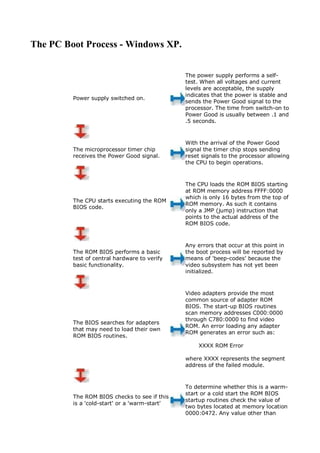
  • 1. The PC Boot Process - Windows XP. The power supply performs a self- test. When all voltages and current levels are acceptable, the supply indicates that the power is stable and Power supply switched on. sends the Power Good signal to the processor. The time from switch-on to Power Good is usually between .1 and .5 seconds. With the arrival of the Power Good The microprocessor timer chip signal the timer chip stops sending receives the Power Good signal. reset signals to the processor allowing the CPU to begin operations. The CPU loads the ROM BIOS starting at ROM memory address FFFF:0000 which is only 16 bytes from the top of The CPU starts executing the ROM ROM memory. As such it contains BIOS code. only a JMP (jump) instruction that points to the actual address of the ROM BIOS code. Any errors that occur at this point in The ROM BIOS performs a basic the boot process will be reported by test of central hardware to verify means of 'beep-codes' because the basic functionality. video subsystem has not yet been initialized. Video adapters provide the most common source of adapter ROM BIOS. The start-up BIOS routines scan memory addresses C000:0000 through C780:0000 to find video The BIOS searches for adapters ROM. An error loading any adapter that may need to load their own ROM generates an error such as: ROM BIOS routines. XXXX ROM Error where XXXX represents the segment address of the failed module. To determine whether this is a warm- start or a cold start the ROM BIOS The ROM BIOS checks to see if this startup routines check the value of is a 'cold-start' or a 'warm-start' two bytes located at memory location 0000:0472. Any value other than
  • 2. 1234h indicates that this is a cold- start. The POST can be broken down into three components: The Video Test initializes the video adapter, tests the video card and If this is a cold-start the ROM BIOS video memory, and displays executes a full POST (Power On configuration information or any Self Test). If this is a warm-start errors. the memory test portion of the The BIOS Identification displays the POST is switched off. BIOS version, manufacturer, and date. The Memory Test tests the memory chips and displays a running sum of installed memory. Errors the occur during the POST can be classified as either 'fatal' or 'non- fatal'. A non-fatal error will typically display an error message on screen and allow the system to continue the boot process. A fatal error, on the other hand, stops the process of booting the computer and is generally signaled by a series of beep-codes. CMOS (which stands for Complementary Metal-Oxide Semiconductor) is a small area of The BIOS locates and reads the memory (64 bytes) which is configuration information stored in maintained by the current of a small CMOS. battery attached to the motherboard. Most importantly for the ROM BIOS startup routines CMOS indicates the order in which drives should be examined for an operating systems - floppy first, CD-Rom first, or fixed disk first. Fixed Disk On a fixed disk the Master Boot Record occupies the very first sector If the first bootable disk is a fixed at cylinder 0, head 0, sector 1. It is disk the BIOS examines the very 512 bytes in size. If this sector is first sector of the disk for a Master found it is loaded into memory at Boot Record (MBR). For a floppy address 0000:7C00 and tested for a the BIOS looks for a Boot Record valid signature. A valid signature in the very first sector. would be the value 55AAh in the last two bytes. Lacking an MBR or a valid signature the boot process halts with an error message which might read: NO ROM BASIC - SYSTEM HALTED
  • 3. A Master Boot Record is made up of two parts - the partition table which describes the layout of the fixed disk and the partition loader code which includes instructions for continuing the boot process. The process of installing multiple With a valid MBR loaded into operating systems on a single PC memory the BIOS transfers control usually involves replacing the original MBR of the boot process to the partition partition loader code with a Boot loader code that takes up most of Loader program that allows the user the 512 bytes of the MBR. to select the specific fixed disk to load in the next step of the process The Boot Record is also 512 bytes and The partition loader (or Boot contains a table that describes the Loader) examines the partition characteristics of the partition Partition table for a partition marked as (number of bytes per sectors, number Table active. The partition loader then of sectors per cluster, etc.) and also searches the very first sector of the jump code that locates the first of that partition for a Boot Record. the operating system files (IO.SYS in DOS). Operating System The loading of Windows XP is controlled by the file NTLDR which is a hidden, system file that resides in the root directory of the system The active partition's boot record is partition. NTLDR will load XP in four checked for a valid boot signature Boot Record stages: and if found the boot sector code is executed as a program. 1) Initial Boot Loader Phase 2) Operating System selection 3) Hardware Detection 4) Configuration Selection During the initial phase NTLDR switches the processor from real- mode to protected mode which places the processor in 32-bit memory mode and turns memory Windows XP supports partitions NTLDR paging on. It then loads the formatted with either the FAT-16, Initial Phase appropriate mini-file system FAT-32, or NTFS file system. drivers to allow NTLDR to load files from a partition formatted with any of the files systems supported by XP. NTLDR If the file BOOT.INI is located in If the file BOOT.INI is not found in the OS Selection the root directory NTLDR will read root directory NTLDR will continue the BOOT.INI it's contents into memory. If boot sequence and attempt to load XP
  • 4. BOOT.INI contains entries for more from the first partition of the first than one operating system NTLDR disk, typically C:. will stop the boot sequence at this point, display a menu of choices, and wait for a specified period of time for the user to make a selection. After each successful boot sequence Assuming that the operating XP makes a copy of the current system being loaded is Windows combination of driver and system NT, 2000, or XP pressing F8 at this settings and stores it as the Last F8 stage of the boot sequence to Known Good Configuration. This display various boot options collection of settings can be used to including "Safe Mode" and "Last boot the system subsequently if the Known Good Configuration" installation of some new device has caused a boot failure. If the selected operating system is NTDETECT.COM collects a list of XP, NTLDR will continue the boot currently installed hardware NTLDR process by locating and loading the components and returns this list for Hardware DOS based NTDETECT.COM later inclusion in the registry under Detection program to perform hardware the HKEY_LOCAL_MACHINE detection. HARDWARE key. If this computer has more than one defined Hardware Profile the NTLDR Lacking more than one Hardware NTLDR program will stop at this Configuration Profile NTLDR will skip this step and point and display the Hardware Selection not display this menu. Profiles/Configuration Recovery menu. During the loading of the kernel (but before it is initialized) NTLDR remains in control of the computer. The screen is cleared and a series of white After selecting a hardware rectangles progress across the bottom configuration (if necessary) NTLDR Kernel Load of the screen. NTLDR also loads the begins loading the XP kernel Hardware Abstraction Layer (NTOSKRNL.EXE). (HAL.DLL) at this time which will insulate the kernel from hardware. Both files are located in the system32 directory. Every driver has a registry subkey entry under HKEY_LOCAL_MACHINE NTLDR now loads device drivers NTLDR SYSTEMServices. Any driver that that are marked as boot devices. Boot has a Start value of With the loading of these drivers Device SERVICE_BOOT_START is considered NTLDR relinquishes control of the Drivers a device to start at boot up. A period computer. is printed to the screen for each loaded file (unless the /SOS switch is
  • 5. used in which case file names are printed. XP disables interrupts during phase 0 and enables them before phase 1. The HAL is called to prepare the interrupt controller; the Memory Manager, Object Manager, Security NTOSKRNL goes through two Reference Monitor, and Process phases in its boot process - phase Manager are initialized. 0 and phase 1. Phase 0 initializes just enough of the microkernel and Phase 1 begins when the HAL is called Executive subsystems so that basic to prepare the system to accept services required for the interrupts from devices. If more than completion of initialization become one processor is present the Kernel additional processors are initialized at Initialization available.. At this point, the system display a graphical screen this point. All Executive subsystems with a status bar indicating load are reinitialized in the following order: status. 1) Object Manager 2) Executive 3) Microkernel 4) Security Reference Monitor 5) Memory Manager 6) Cache Manager 7) LPCS 8) I/O Manager 9) Process Manager The initialization of I/O Manager begins the process of loading all the systems driver files. Picking up The failure of a driver to load may where NTLDR left off, it first prompt NT to reboot and try to start I/O Manager finishes the loading of boot the system using the values stored in devices. Next it assembles a the Last Known Good Configuration. prioritized list of drivers and attempts to load each in turn. SMSS runs in user-mode but unlike The last task for phase 1 other user-mode applications SMSS is initialization of the kernel is to considered a trusted part of the launch the Session Manager operating system and is also a native SMSS Subsystem (SMSS). SMSS is application (it uses only core responsible for creating the user- Executive functions). These two mode environment that provides features allow SMSS to start the the visible interface to NT. graphics subsystem and login processes. Shortly after win32k.sys starts it SMSS loads the win32k.sys device switches the screen into graphics win32k.sys driver which implements the mode. The Services Subsystem now Win32 graphics subsystem. starts all services mark as Auto Start. Once all devices and services are
  • 6. started the boot is deemed successful and this configuration is saved as the Last Known Good Configuration. The XP boot process is not considered complete until a user has successfully logged onto the system. The process is begun by This dialog box appears at the WINLOGON.EXE file which is approximately the time that the Logon loaded as a service by the kernel Services Subsystem starts the and continued by the Local network service. Security Authority (LSASS.EXE) which displays the logon dialog box.