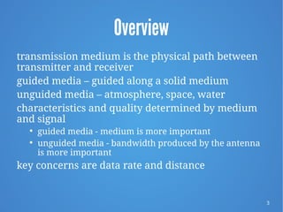
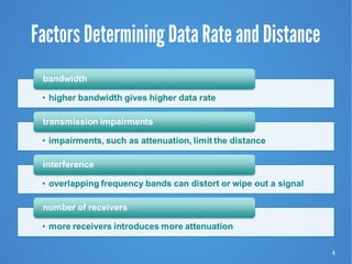
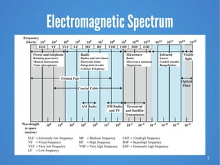
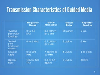
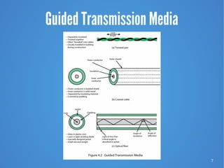
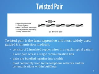
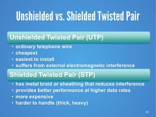
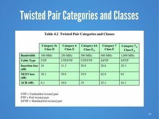
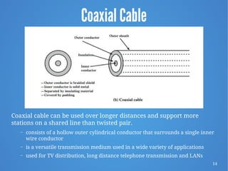
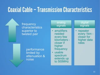
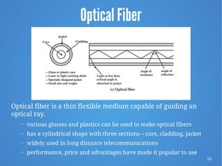
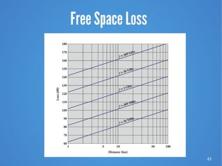
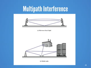
Transmission Media
CEN 220/CIS 192 Advanced Data Communications and Networking
Data and Computer Communications, W. Stallings 9/E, Chapter 4
2
Data Link Control Protocols
“Communication channels in the animal world include
touch, sound, sight, and scent. Electric eels even use
electric pulses. Ravens also are very expressive. By a
combination voice, patterns of feather erection and
body posture ravens communicate so clearly that an
experienced observer can identify anger, affection,
hunger, curiosity, playfulness, fright, boldness, and
depression.”
—Mind of the Raven,
Bernd Heinrich
3
Overview
transmission medium is the physical path between
transmitter and receiver
guided media – guided along a solid medium
unguided media – atmosphere, space, water
characteristics and quality determined by medium
and signal

guided media - medium is more important

unguided media - bandwidth produced by the antenna
is more important
key concerns are data rate and distance
4
Factors Determining Data Rate and Distance
5
Electromagnetic Spectrum
6
Transmission Characteristics of Guided Media
 
  Frequency
Range
Typical
Attenuation
Typical
Delay
Repeater
Spacing
Twisted
pair (with
loading)
0 to 3.5
kHz
0.2 dB/km
@ 1 kHz
50 µs/km 2 km
Twisted
pairs
(multi-pair
cables)
0 to 1 MHz 0.7 dB/km
@ 1 kHz
5 µs/km 2 km
Coaxial
cable
0 to 500
MHz
7 dB/km @
10 MHz
4 µs/km 1 to 9 km
Optical
fiber
186 to 370
THz
0.2 to 0.5
dB/km
5 µs/km 40 km
7
Guided Transmission Media
8
Twisted Pair
Twisted pair is the least expensive and most widely used
guided transmission medium.
– consists of 2 insulated copper wires in a regular spiral pattern
– a wire pair acts as a single communication link
– pairs are bundled together into a cable
– most commonly used in the telephone network and for
communications within buildings
9
Twisted Pair - Transmission
Characteristics
susceptible to interference
and noise
10
Unshielded vs. Shielded Twisted Pair
11
Twisted Pair Categories and Classes
12
Near End Crosstalk
coupling of signal from one pair of conductors to
another
occurs when transmit signal entering the link
couples back to the receiving pair -
(near transmitted signal is picked up by
near receiving pair)
13
Signal Power Relationships
14
Coaxial Cable
Coaxial cable can be used over longer distances and support more
stations on a shared line than twisted pair.
– consists of a hollow outer cylindrical conductor that surrounds a single inner
wire conductor
– is a versatile transmission medium used in a wide variety of applications
– used for TV distribution, long distance telephone transmission and LANs
15
Coaxial Cable – Transmission Characteristics
16
Optical Fiber
Optical fiber is a thin flexible medium capable of guiding an
optical ray.
– various glasses and plastics can be used to make optical fibers
– has a cylindrical shape with three sections – core, cladding, jacket
– widely used in long distance telecommunications
– performance, price and advantages have made it popular to use
17
Optical Fiber - Benefits
greater capacity

data rates of hundreds of Gbps
smaller size and lighter weight

considerably thinner than coaxial or twisted pair cable

reduces structural support requirements
lower attenuation
electromagnetic isolation

not vulnerable to interference, impulse noise, or crosstalk

high degree of security from eavesdropping
greater repeater spacing

lower cost and fewer sources of error
18
Optical Fiber - Transmission Characteristics
uses total internal reflection to transmit light
– effectively acts as wave guide for 1014 to 1015 Hz (this
covers portions of infrared & visible spectra)
light sources used:
– Light Emitting Diode (LED)
●
cheaper, operates over a greater temperature range, lasts
longer
– Injection Laser Diode (ILD)
●
more efficient, has greater data rates
has a relationship among wavelength, type of
transmission and achievable data rate
19
Optical Fiber Transmission Modes
20
Frequency Utilization for Fiber
Applications
Wavelength (in
vacuum) range
(nm)
Frequency
Range (THz)
Band
Label
Fiber Type Application
820 to 900 366 to 333 Multimode LAN
1280 to 1350 234 to 222 S Single mode Various
1528 to 1561 196 to 192 C Single mode WDM
1561 to 1620 192 to 185 L Single mode WDM
WDM (wavelength division multiplexing)
21
Attenuation in Guided Media
22
Wireless Transmission Frequencies
23
Antennas
electrical conductors
used to radiate or collect
electromagnetic energy
same antenna is often
used for both purposes
24
Radiation Pattern
power radiated in all directions
does not perform equally well in all directions

as seen in a radiation pattern diagram
an isotropic antenna is a point in space that radiates
power

in all directions equally

with a spherical radiation pattern
25
Parabolic Reflective Antenna
26
Antenna Gain
measure of the directionality of an antenna
power output in particular direction verses that
produced by an isotropic antenna
measured in decibels (dB)
results in loss in power in another direction
effective area relates to physical size and shape
27
Terrestrial Microwave
28
Terrestrial Microwave Applications
used for long haul telecommunications, short
point-to-point links between buildings and cellular
systems
used for both voice and TV transmission
fewer repeaters but requires line of sight
transmission
1-40GHz frequencies, with higher frequencies
having higher data rates
main source of loss is attenuation caused mostly by
distance, rainfall and interference
29
Microwave Bandwidth and Data Rates
30
Satellite Microwave
a communication satellite is in effect a microwave relay
station
used to link two or more ground stations
receives on one frequency, amplifies or repeats signal
and transmits on another frequency

frequency bands are called transponder channels
requires geo-stationary orbit

rotation match occurs at a height of 35,863 km at the equator
 need to be spaced at least 3° - 4° apart to avoid interfering
with each other

spacing limits the number of possible satellites
31
Satellite Point-to-Point Link
32
Satellite Broadcast Link
33
Satellite Microwave Applications
private business networks
– satellite providers can divide capacity into channels to lease to
individual business users
television distribution
– programs are transmitted to the satellite then broadcast down
to a number of stations which then distributes the programs to
individual viewers
– Direct Broadcast Satellite (DBS) transmits video signals directly
to the home user
global positioning
– Navstar Global Positioning System (GPS)
34
Transmission Characteristics
the optimum frequency range for satellite transmission
is 1 to 10 GHz
– lower has significant noise from natural sources
– higher is attenuated by atmospheric absorption and
precipitation
satellites use a frequency bandwidth range of 5.925 to
6.425 GHz from earth to satellite (uplink) and a range
of 3.7 to 4.2 GHz from satellite to earth (downlink)
– this is referred to as the 4/6-GHz band
– because of saturation the 12/14-GHz band has been
developed (uplink: 14 - 14.5 GHz; downlink: 11.7 - 12.2 GHz
35
Broadcast Radio
radio is the term used to encompass frequencies in the
range of 3 kHz to 300 GHz
broadcast radio (30 MHz – 1 GHz) covers
– FM radio
– UHF and VHF television
– data networking applications
omnidirectional
limited to line of sight
suffers from multi-path interference
– reflections from land, water, man-made objects
36
Infrared
achieved using transceivers that modulate
non-coherent infrared light
transceivers must be within line of sight of each
other directly or via reflection
does not penetrate walls
no licenses required
no frequency allocation issues
typical uses: TV remote control
37
Frequency Bands
38
Wireless Propagation Ground Wave
ground wave propagation follows the contour of the earth
and can propagate distances well over the visible horizon
this effect is found in frequencies up to 2MHz
best example of ground wave communication is AM radio
39
Wireless Propagation Sky Wave
sky wave propagation is used for amateur radio, CB radio, and
international broadcasts, e.g., BBC, Voice of America
a signal from an earth based antenna is reflected from the
ionized layer of the upper atmosphere back down to earth
sky wave signals can travel through a number of hops, bouncing
back and for the between the ionosphere and the earth’s surface
40
Wireless Propagation Line of Sight
ground and sky wave propagation modes do
not operate above 30-MHz
communication must be by line of sight
41
Refraction
velocity of electromagnetic wave is a function of the
density of the medium through which it travels
– ~3 x 10⁸ m/s in vacuum, less in anything else
speed changes with movement between media
index of refraction (refractive index) is
– sine (incidence) / sine (refraction)
– varies with wavelength
gradual bending
– density of atmosphere decreases with height, resulting in
bending of radio waves towards earth
42
Line of Sight Transmission
43
Free Space Loss
44
Multipath Interference
45
Summary
transmission Media
– physical path between transmitter and receiver
– bandwidth, transmission impairments, interference, number of
receivers
guided Media
– twisted pair, coaxial cable, optical fiber
wireless Transmission
– microwave frequencies
– antennas, terrestrial microwave, satellite microwave, broadcast
radio
wireless Propagation
– ground wave, sky wave, line of sight

Chapter 4 - Transmission Media 9e

  • 1.
    Transmission Media CEN 220/CIS192 Advanced Data Communications and Networking Data and Computer Communications, W. Stallings 9/E, Chapter 4
  • 2.
    2 Data Link ControlProtocols “Communication channels in the animal world include touch, sound, sight, and scent. Electric eels even use electric pulses. Ravens also are very expressive. By a combination voice, patterns of feather erection and body posture ravens communicate so clearly that an experienced observer can identify anger, affection, hunger, curiosity, playfulness, fright, boldness, and depression.” —Mind of the Raven, Bernd Heinrich
  • 3.
    3 Overview transmission medium isthe physical path between transmitter and receiver guided media – guided along a solid medium unguided media – atmosphere, space, water characteristics and quality determined by medium and signal  guided media - medium is more important  unguided media - bandwidth produced by the antenna is more important key concerns are data rate and distance
  • 4.
    4 Factors Determining DataRate and Distance
  • 5.
  • 6.
    6 Transmission Characteristics ofGuided Media     Frequency Range Typical Attenuation Typical Delay Repeater Spacing Twisted pair (with loading) 0 to 3.5 kHz 0.2 dB/km @ 1 kHz 50 µs/km 2 km Twisted pairs (multi-pair cables) 0 to 1 MHz 0.7 dB/km @ 1 kHz 5 µs/km 2 km Coaxial cable 0 to 500 MHz 7 dB/km @ 10 MHz 4 µs/km 1 to 9 km Optical fiber 186 to 370 THz 0.2 to 0.5 dB/km 5 µs/km 40 km
  • 7.
  • 8.
    8 Twisted Pair Twisted pairis the least expensive and most widely used guided transmission medium. – consists of 2 insulated copper wires in a regular spiral pattern – a wire pair acts as a single communication link – pairs are bundled together into a cable – most commonly used in the telephone network and for communications within buildings
  • 9.
    9 Twisted Pair -Transmission Characteristics susceptible to interference and noise
  • 10.
  • 11.
  • 12.
    12 Near End Crosstalk couplingof signal from one pair of conductors to another occurs when transmit signal entering the link couples back to the receiving pair - (near transmitted signal is picked up by near receiving pair)
  • 13.
  • 14.
    14 Coaxial Cable Coaxial cablecan be used over longer distances and support more stations on a shared line than twisted pair. – consists of a hollow outer cylindrical conductor that surrounds a single inner wire conductor – is a versatile transmission medium used in a wide variety of applications – used for TV distribution, long distance telephone transmission and LANs
  • 15.
    15 Coaxial Cable –Transmission Characteristics
  • 16.
    16 Optical Fiber Optical fiberis a thin flexible medium capable of guiding an optical ray. – various glasses and plastics can be used to make optical fibers – has a cylindrical shape with three sections – core, cladding, jacket – widely used in long distance telecommunications – performance, price and advantages have made it popular to use
  • 17.
    17 Optical Fiber -Benefits greater capacity  data rates of hundreds of Gbps smaller size and lighter weight  considerably thinner than coaxial or twisted pair cable  reduces structural support requirements lower attenuation electromagnetic isolation  not vulnerable to interference, impulse noise, or crosstalk  high degree of security from eavesdropping greater repeater spacing  lower cost and fewer sources of error
  • 18.
    18 Optical Fiber -Transmission Characteristics uses total internal reflection to transmit light – effectively acts as wave guide for 1014 to 1015 Hz (this covers portions of infrared & visible spectra) light sources used: – Light Emitting Diode (LED) ● cheaper, operates over a greater temperature range, lasts longer – Injection Laser Diode (ILD) ● more efficient, has greater data rates has a relationship among wavelength, type of transmission and achievable data rate
  • 19.
  • 20.
    20 Frequency Utilization forFiber Applications Wavelength (in vacuum) range (nm) Frequency Range (THz) Band Label Fiber Type Application 820 to 900 366 to 333 Multimode LAN 1280 to 1350 234 to 222 S Single mode Various 1528 to 1561 196 to 192 C Single mode WDM 1561 to 1620 192 to 185 L Single mode WDM WDM (wavelength division multiplexing)
  • 21.
  • 22.
  • 23.
    23 Antennas electrical conductors used toradiate or collect electromagnetic energy same antenna is often used for both purposes
  • 24.
    24 Radiation Pattern power radiatedin all directions does not perform equally well in all directions  as seen in a radiation pattern diagram an isotropic antenna is a point in space that radiates power  in all directions equally  with a spherical radiation pattern
  • 25.
  • 26.
    26 Antenna Gain measure ofthe directionality of an antenna power output in particular direction verses that produced by an isotropic antenna measured in decibels (dB) results in loss in power in another direction effective area relates to physical size and shape
  • 27.
  • 28.
    28 Terrestrial Microwave Applications usedfor long haul telecommunications, short point-to-point links between buildings and cellular systems used for both voice and TV transmission fewer repeaters but requires line of sight transmission 1-40GHz frequencies, with higher frequencies having higher data rates main source of loss is attenuation caused mostly by distance, rainfall and interference
  • 29.
  • 30.
    30 Satellite Microwave a communicationsatellite is in effect a microwave relay station used to link two or more ground stations receives on one frequency, amplifies or repeats signal and transmits on another frequency  frequency bands are called transponder channels requires geo-stationary orbit  rotation match occurs at a height of 35,863 km at the equator  need to be spaced at least 3° - 4° apart to avoid interfering with each other  spacing limits the number of possible satellites
  • 31.
  • 32.
  • 33.
    33 Satellite Microwave Applications privatebusiness networks – satellite providers can divide capacity into channels to lease to individual business users television distribution – programs are transmitted to the satellite then broadcast down to a number of stations which then distributes the programs to individual viewers – Direct Broadcast Satellite (DBS) transmits video signals directly to the home user global positioning – Navstar Global Positioning System (GPS)
  • 34.
    34 Transmission Characteristics the optimumfrequency range for satellite transmission is 1 to 10 GHz – lower has significant noise from natural sources – higher is attenuated by atmospheric absorption and precipitation satellites use a frequency bandwidth range of 5.925 to 6.425 GHz from earth to satellite (uplink) and a range of 3.7 to 4.2 GHz from satellite to earth (downlink) – this is referred to as the 4/6-GHz band – because of saturation the 12/14-GHz band has been developed (uplink: 14 - 14.5 GHz; downlink: 11.7 - 12.2 GHz
  • 35.
    35 Broadcast Radio radio isthe term used to encompass frequencies in the range of 3 kHz to 300 GHz broadcast radio (30 MHz – 1 GHz) covers – FM radio – UHF and VHF television – data networking applications omnidirectional limited to line of sight suffers from multi-path interference – reflections from land, water, man-made objects
  • 36.
    36 Infrared achieved using transceiversthat modulate non-coherent infrared light transceivers must be within line of sight of each other directly or via reflection does not penetrate walls no licenses required no frequency allocation issues typical uses: TV remote control
  • 37.
  • 38.
    38 Wireless Propagation GroundWave ground wave propagation follows the contour of the earth and can propagate distances well over the visible horizon this effect is found in frequencies up to 2MHz best example of ground wave communication is AM radio
  • 39.
    39 Wireless Propagation SkyWave sky wave propagation is used for amateur radio, CB radio, and international broadcasts, e.g., BBC, Voice of America a signal from an earth based antenna is reflected from the ionized layer of the upper atmosphere back down to earth sky wave signals can travel through a number of hops, bouncing back and for the between the ionosphere and the earth’s surface
  • 40.
    40 Wireless Propagation Lineof Sight ground and sky wave propagation modes do not operate above 30-MHz communication must be by line of sight
  • 41.
    41 Refraction velocity of electromagneticwave is a function of the density of the medium through which it travels – ~3 x 10⁸ m/s in vacuum, less in anything else speed changes with movement between media index of refraction (refractive index) is – sine (incidence) / sine (refraction) – varies with wavelength gradual bending – density of atmosphere decreases with height, resulting in bending of radio waves towards earth
  • 42.
    42 Line of SightTransmission
  • 43.
  • 44.
  • 45.
    45 Summary transmission Media – physicalpath between transmitter and receiver – bandwidth, transmission impairments, interference, number of receivers guided Media – twisted pair, coaxial cable, optical fiber wireless Transmission – microwave frequencies – antennas, terrestrial microwave, satellite microwave, broadcast radio wireless Propagation – ground wave, sky wave, line of sight