Download as PPSX, PPTX
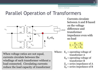

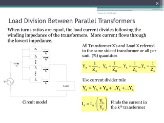
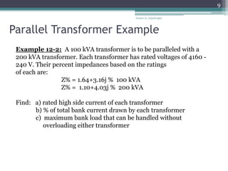
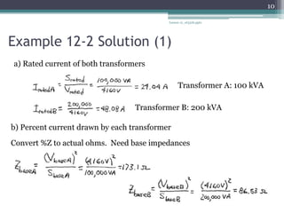
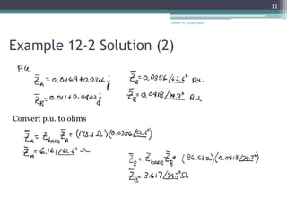
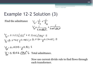
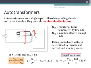
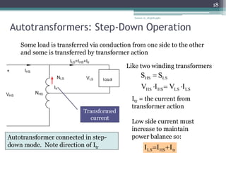
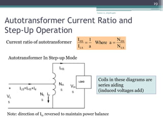
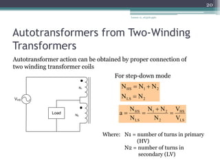
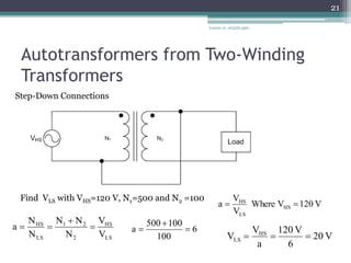
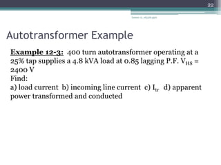
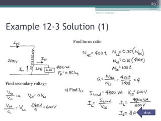
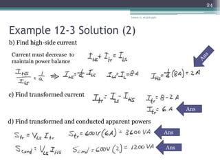

This document discusses parallel and autotransformer operations. It begins by explaining how circulating currents occur in parallel transformers when their voltage ratios are unequal and how this reduces their load capacity. It then covers methods for calculating circulating current values and load division between parallel transformers. The document next discusses how autotransformers operate using a single tapped coil to change voltages and provides examples for calculating step-down, step-up, and load values. It concludes by showing how an autotransformer can be modeled from a two-winding transformer connection.