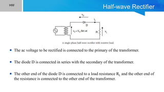
1) We need rectifiers to convert alternating current (AC) from power lines to direct current (DC) required by electronic devices. Rectifiers use diodes and transformers to convert the sinusoidal AC voltage into a pulsing DC voltage.
2) Transformers are used in rectifiers to either increase or decrease the AC voltage as needed. They work on the principle of electromagnetic induction to induce an alternating voltage in the secondary winding.
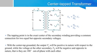
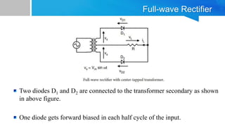
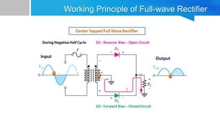
3) A full-wave rectifier uses a center-tapped transformer and two diodes to rectify both halves of the AC input waveform, doubling the output voltage compared to a half-wave rectifier.