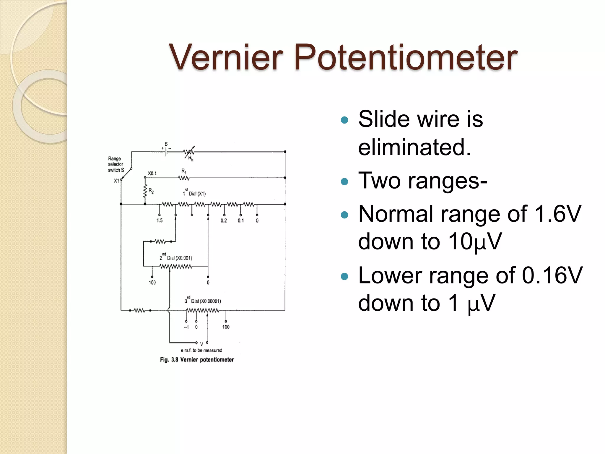
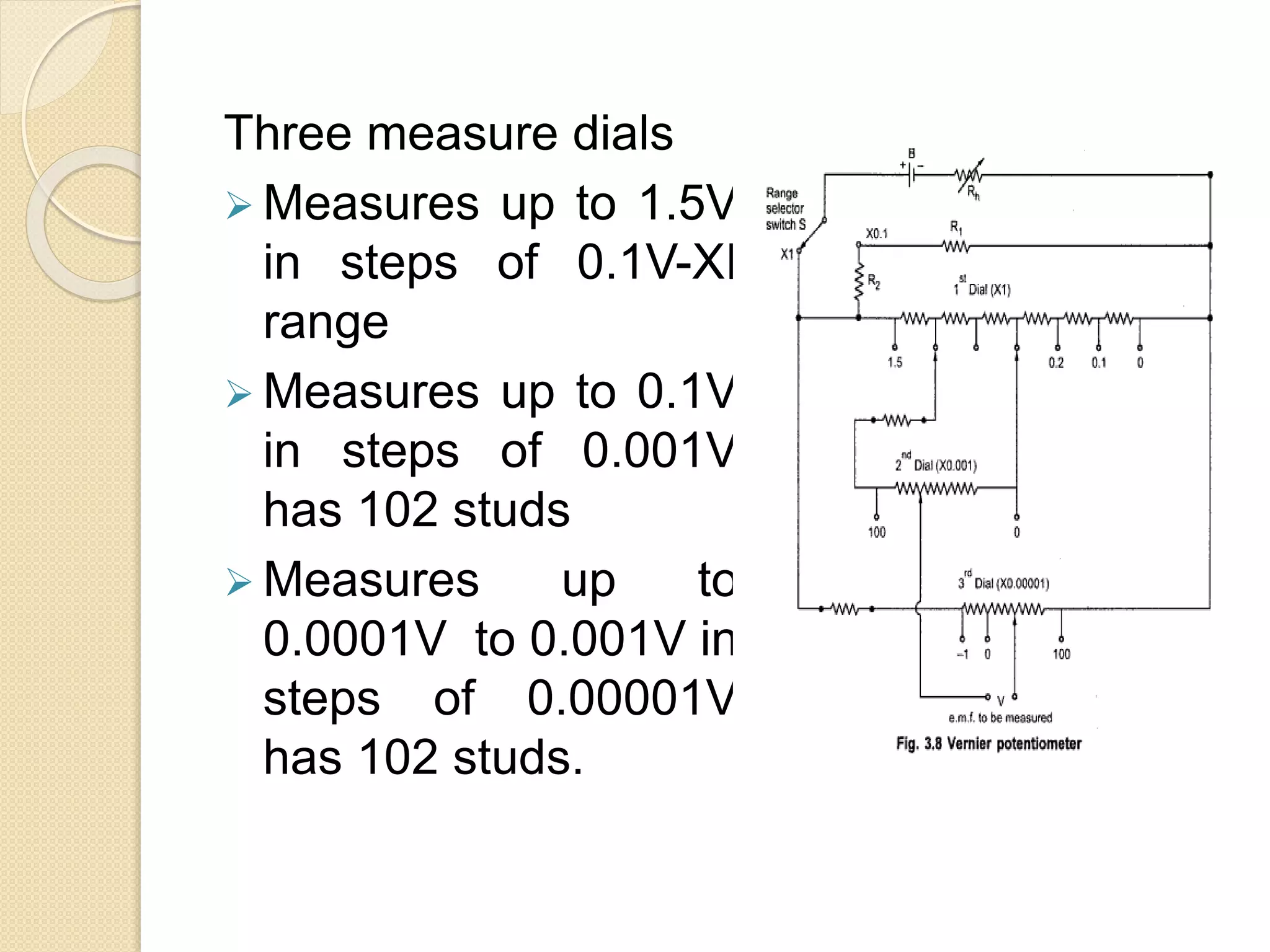
DC & AC Potentiometers
Vernier Potentiometer
 Slide wire is
eliminated.
 Two ranges-
 Normal range of 1.6V
down to 10μV
 Lower range of 0.16V
down to 1 μV
Three measure dials
 Measures up to 1.5V
in steps of 0.1V-XI
range
 Measures up to 0.1V
in steps of 0.001V
has 102 studs
 Measures up to
0.0001V to 0.001V in
steps of 0.00001V
has 102 studs.
 The resistance of the
middle dial shunts
two of the coils of
first dial.
 The moving arm of
middle dial carries
two arms spaced two
studs.
 The vernier
potentiometer reads
to increment of 10
μV on range of X1
and has readability
of 1 μV on X0.1
range
 If a third range of X0.01
is provided, the
readability becomes 0.1
μV.
 Measurements are
subjected to stray
thermal and contact
emfs in the
potentiometer,
galvanometer and the
measuring circuits.
 These emfs can be
minimised by properly
selecting metals for
resistors, terminals and
connecting leads.
AC Potentiometer
 Its principle is same as a d.c. potentiometer.
 One very important difference between the
two. In d.c. potentiometer, only the
magnitudes of the unknown e.m.f. and slide-
wire voltage drop are made equal for
obtaining balance.
 But in an a.c. potentiometer, not only the
magnitudes but phases as well have to be
equal for obtaining balance.
 To avoid frequency and waveform errors, the
a.c. supply for slide-wire must be taken from
same source as the voltage or current to be
measured.
Types
Polar potentiometers in which
the unknown voltage is
measured in polar form i.e. in
terms of magnitude and relative
phase.
Co-ordinate potentiometers
which measure the rectangular
co-ordinates of the voltage under
DRYSDALE POLAR TYPE AC
POTENTIOMETER
DRYSDALE POLAR TYPE AC
POTENTIOMETER
 It is basic d.c.
potentiometers along
with some auxillary
components such as,
drysdale phase shifter
and
electrodynamometer
type ammeter.
 Drysdale phase shifter
is also known as phase
shifting transformer.
 It consists of a ring
shaped laminated steel
stator.
DRYSDALE POLAR TYPE AC
POTENTIOMETER
 This sector is wound
with either a two
phase or three phase
winding.
 Inside it there is a
laminated rotor
keeping some air gap
between it and stator.
 The rotor consists of a
winding provided in
the slot which supplies
voltage to slide wire
circuit of
potentiometer.
 When the current flows through stator
winding, a rotating field is produced inducing
e.m.f in the rotor.
 The phase of rotor current can be changed
through any angle relative to stator supply
voltage by rotating rotor.
 Thus the change in the phase of secondary
e.m.f. is equal to the angle through which
rotor is moved from its original zero position.
 It is very important to arrange windings such
that even though the magnitude of emf
induced in rotor is changed, phase remains
unchanged.
 The phase angle can be directly read with the
help of scale fixed on top of the instrument.
 The variable capacitor and resistor
shown are so adjusted to obtain exact
quadrature component between the
two stator winding currents.
Standardization of Polar AC
Potentiometer
 Both d.c. as well as a.c. standardization is
done.
 The d.c. standardization is done first by
replacing vibration galvanometer by
D’arsonval galvanometer.
 A standard cell such as Weston cell is used
for d.c standardization.
 Then by adjusting sliding contacts null
deflection in galvanometer is achieved.
 The reading of a precision ammeter included
in battery supply is noted. During a.c.
standardization again vibration galvanometer
is used.
Measurement of Unknown
E.M.F.
 An emf to be
measured connected
across terminals A-
A’.
 Sliding contacts P1
and P2 and the
position of rotor in
phase shifter are
adjusted
simultaneously till
the balance is
obtained as
indicated by the null
deflection of
 At balance, the
magnitude of the
unknown emf is
obtained from P1 and
P2 and the phase
angle is measured
from the scale
reading which is
mounted on the top
of the instrument.
Thus the unknown
emf can be
expressed in polar
form as E∟Ө°.
GALL TINSLEY CO-ORDINATE
TYPE AC POTENTIOMETER
GALL TINSLEY CO-ORDINATE
TYPE AC POTENTIOMETER
 The in-phase and
quadrature
potentiometer consist
of sliding contacts BB’
and CC’ respectively.
 Rheostats R and R’
are also provided in
the respective
potentiometers for the
adjustment of current.
GALL TINSLEY CO-ORDINATE
TYPE AC POTENTIOMETER
 By using different
arrangement, the
supply for the
potentiometer are
obtained.
 A vibration
galvanometer VG is
tuned to the supply freq
and it is connected in
series with a switch K
and
electrodynamometer
type ammeter.
 S1 and S2 are the sign changing
switches which are necessary for
reversing the direction of unknown
emf. The unknown voltage is
introduced using selector switch S3
which is having 4 pair of terminals.
 T1 and T2 are step
down transformers
and they supply
about 6 to 8 volts to
potentiometers.
 By using variable
resistor and
capacitor, the supply
for T2 is obatained.
 By adjusting R & C
,quadrature is
obtained.
Standardization
 The d.c. standardization is done first by using
standard cell.
 Then without disturbing this setting, ac
standardisation is done by adjusting slide
wire current to give zero deflection.
 Then previous galvanometer is replaced by
vibration galvanometer and also DC supply is
replaced by AC supply.
 The rheostat is adjusted till the current in the
quadrature potentiometer wire is same as
that in the inphase potentiometer magnitude
wise.
 Also these two currents must be exactly in
quadrature.
Measurement of Unknown
EMF
 The emf to be
measured is
connected across
the terminals A-A’
using selector switch
S3.
 Sliding contacts of
both the
potentiometers are
adjusted till the
contacts of both the
potentiometers are
adjusted till the null
deflection is
obtained.
Measurement of Unknown
EMF
 Under the balance
condition, the in-phase
component of the
unknown emf is obtained
from inphase
potentiometer while the
quadrature component
of the unknown emf is
obtained from
quadrature
potentiometer.
 If needed the polarity of
the test voltage may be
reversed by using sign
changing switches S1
and S2 to balance the
potentiometer.
The following types of instruments are used as detector in bridge and potentiometers
• Vibration galvanometer
• Head phones (speaker)
• Tuned amplifier
Vibration galvanometer
A vibration galvanometer is connected to indicate the bridge balance condition. This
A.C. galvanometer which works on the principle of resonance. The A.C.
galvanometer shows a dot, if the bridge is unbalanced.
Head phones
Two speakers are connected in parallel in this system. If the bridge is unbalanced, the
speaker produced more sound energy. If the bridge is balanced, the speaker do not
produced
any sound energy.
Tuned amplifier
If the bridge is unbalanced the output of tuned amplifier is high. If the bridge is
balanced,
output of amplifier is zero.

potentiometer II.pptx

  • 1.
    DC & ACPotentiometers
  • 2.
    Vernier Potentiometer  Slidewire is eliminated.  Two ranges-  Normal range of 1.6V down to 10μV  Lower range of 0.16V down to 1 μV
  • 4.
    Three measure dials Measures up to 1.5V in steps of 0.1V-XI range  Measures up to 0.1V in steps of 0.001V has 102 studs  Measures up to 0.0001V to 0.001V in steps of 0.00001V has 102 studs.
  • 5.
     The resistanceof the middle dial shunts two of the coils of first dial.  The moving arm of middle dial carries two arms spaced two studs.  The vernier potentiometer reads to increment of 10 μV on range of X1 and has readability of 1 μV on X0.1 range
  • 6.
     If athird range of X0.01 is provided, the readability becomes 0.1 μV.  Measurements are subjected to stray thermal and contact emfs in the potentiometer, galvanometer and the measuring circuits.  These emfs can be minimised by properly selecting metals for resistors, terminals and connecting leads.
  • 7.
    AC Potentiometer  Itsprinciple is same as a d.c. potentiometer.  One very important difference between the two. In d.c. potentiometer, only the magnitudes of the unknown e.m.f. and slide- wire voltage drop are made equal for obtaining balance.  But in an a.c. potentiometer, not only the magnitudes but phases as well have to be equal for obtaining balance.  To avoid frequency and waveform errors, the a.c. supply for slide-wire must be taken from same source as the voltage or current to be measured.
  • 8.
    Types Polar potentiometers inwhich the unknown voltage is measured in polar form i.e. in terms of magnitude and relative phase. Co-ordinate potentiometers which measure the rectangular co-ordinates of the voltage under
  • 9.
    DRYSDALE POLAR TYPEAC POTENTIOMETER
  • 10.
    DRYSDALE POLAR TYPEAC POTENTIOMETER  It is basic d.c. potentiometers along with some auxillary components such as, drysdale phase shifter and electrodynamometer type ammeter.  Drysdale phase shifter is also known as phase shifting transformer.  It consists of a ring shaped laminated steel stator.
  • 11.
    DRYSDALE POLAR TYPEAC POTENTIOMETER  This sector is wound with either a two phase or three phase winding.  Inside it there is a laminated rotor keeping some air gap between it and stator.  The rotor consists of a winding provided in the slot which supplies voltage to slide wire circuit of potentiometer.
  • 12.
     When thecurrent flows through stator winding, a rotating field is produced inducing e.m.f in the rotor.  The phase of rotor current can be changed through any angle relative to stator supply voltage by rotating rotor.  Thus the change in the phase of secondary e.m.f. is equal to the angle through which rotor is moved from its original zero position.  It is very important to arrange windings such that even though the magnitude of emf induced in rotor is changed, phase remains unchanged.  The phase angle can be directly read with the help of scale fixed on top of the instrument.
  • 13.
     The variablecapacitor and resistor shown are so adjusted to obtain exact quadrature component between the two stator winding currents.
  • 14.
    Standardization of PolarAC Potentiometer  Both d.c. as well as a.c. standardization is done.  The d.c. standardization is done first by replacing vibration galvanometer by D’arsonval galvanometer.  A standard cell such as Weston cell is used for d.c standardization.  Then by adjusting sliding contacts null deflection in galvanometer is achieved.  The reading of a precision ammeter included in battery supply is noted. During a.c. standardization again vibration galvanometer is used.
  • 15.
    Measurement of Unknown E.M.F. An emf to be measured connected across terminals A- A’.  Sliding contacts P1 and P2 and the position of rotor in phase shifter are adjusted simultaneously till the balance is obtained as indicated by the null deflection of
  • 16.
     At balance,the magnitude of the unknown emf is obtained from P1 and P2 and the phase angle is measured from the scale reading which is mounted on the top of the instrument. Thus the unknown emf can be expressed in polar form as E∟Ө°.
  • 17.
  • 18.
    GALL TINSLEY CO-ORDINATE TYPEAC POTENTIOMETER  The in-phase and quadrature potentiometer consist of sliding contacts BB’ and CC’ respectively.  Rheostats R and R’ are also provided in the respective potentiometers for the adjustment of current.
  • 19.
    GALL TINSLEY CO-ORDINATE TYPEAC POTENTIOMETER  By using different arrangement, the supply for the potentiometer are obtained.  A vibration galvanometer VG is tuned to the supply freq and it is connected in series with a switch K and electrodynamometer type ammeter.
  • 20.
     S1 andS2 are the sign changing switches which are necessary for reversing the direction of unknown emf. The unknown voltage is introduced using selector switch S3 which is having 4 pair of terminals.
  • 21.
     T1 andT2 are step down transformers and they supply about 6 to 8 volts to potentiometers.  By using variable resistor and capacitor, the supply for T2 is obatained.  By adjusting R & C ,quadrature is obtained.
  • 22.
    Standardization  The d.c.standardization is done first by using standard cell.  Then without disturbing this setting, ac standardisation is done by adjusting slide wire current to give zero deflection.  Then previous galvanometer is replaced by vibration galvanometer and also DC supply is replaced by AC supply.  The rheostat is adjusted till the current in the quadrature potentiometer wire is same as that in the inphase potentiometer magnitude wise.  Also these two currents must be exactly in quadrature.
  • 23.
    Measurement of Unknown EMF The emf to be measured is connected across the terminals A-A’ using selector switch S3.  Sliding contacts of both the potentiometers are adjusted till the contacts of both the potentiometers are adjusted till the null deflection is obtained.
  • 24.
    Measurement of Unknown EMF Under the balance condition, the in-phase component of the unknown emf is obtained from inphase potentiometer while the quadrature component of the unknown emf is obtained from quadrature potentiometer.  If needed the polarity of the test voltage may be reversed by using sign changing switches S1 and S2 to balance the potentiometer.
  • 25.
    The following typesof instruments are used as detector in bridge and potentiometers • Vibration galvanometer • Head phones (speaker) • Tuned amplifier Vibration galvanometer A vibration galvanometer is connected to indicate the bridge balance condition. This A.C. galvanometer which works on the principle of resonance. The A.C. galvanometer shows a dot, if the bridge is unbalanced. Head phones Two speakers are connected in parallel in this system. If the bridge is unbalanced, the speaker produced more sound energy. If the bridge is balanced, the speaker do not produced any sound energy. Tuned amplifier If the bridge is unbalanced the output of tuned amplifier is high. If the bridge is balanced, output of amplifier is zero.